US9470203B2 - Ion current detector - Google Patents
Ion current detector Download PDFInfo
- Publication number
- US9470203B2 US9470203B2 US12/506,010 US50601009A US9470203B2 US 9470203 B2 US9470203 B2 US 9470203B2 US 50601009 A US50601009 A US 50601009A US 9470203 B2 US9470203 B2 US 9470203B2
- Authority
- US
- United States
- Prior art keywords
- ion current
- ion
- ignition signal
- amplification factor
- ignition
- Prior art date
- Legal status (The legal status is an assumption and is not a legal conclusion. Google has not performed a legal analysis and makes no representation as to the accuracy of the status listed.)
- Expired - Fee Related, expires
Links
Images


Classifications
-
- F—MECHANICAL ENGINEERING; LIGHTING; HEATING; WEAPONS; BLASTING
- F02—COMBUSTION ENGINES; HOT-GAS OR COMBUSTION-PRODUCT ENGINE PLANTS
- F02P—IGNITION, OTHER THAN COMPRESSION IGNITION, FOR INTERNAL-COMBUSTION ENGINES; TESTING OF IGNITION TIMING IN COMPRESSION-IGNITION ENGINES
- F02P17/00—Testing of ignition installations, e.g. in combination with adjusting; Testing of ignition timing in compression-ignition engines
- F02P17/12—Testing characteristics of the spark, ignition voltage or current
-
- F—MECHANICAL ENGINEERING; LIGHTING; HEATING; WEAPONS; BLASTING
- F02—COMBUSTION ENGINES; HOT-GAS OR COMBUSTION-PRODUCT ENGINE PLANTS
- F02D—CONTROLLING COMBUSTION ENGINES
- F02D35/00—Controlling engines, dependent on conditions exterior or interior to engines, not otherwise provided for
- F02D35/02—Controlling engines, dependent on conditions exterior or interior to engines, not otherwise provided for on interior conditions
- F02D35/021—Controlling engines, dependent on conditions exterior or interior to engines, not otherwise provided for on interior conditions using an ionic current sensor
-
- F—MECHANICAL ENGINEERING; LIGHTING; HEATING; WEAPONS; BLASTING
- F02—COMBUSTION ENGINES; HOT-GAS OR COMBUSTION-PRODUCT ENGINE PLANTS
- F02P—IGNITION, OTHER THAN COMPRESSION IGNITION, FOR INTERNAL-COMBUSTION ENGINES; TESTING OF IGNITION TIMING IN COMPRESSION-IGNITION ENGINES
- F02P5/00—Advancing or retarding ignition; Control therefor
- F02P5/04—Advancing or retarding ignition; Control therefor automatically, as a function of the working conditions of the engine or vehicle or of the atmospheric conditions
- F02P5/145—Advancing or retarding ignition; Control therefor automatically, as a function of the working conditions of the engine or vehicle or of the atmospheric conditions using electrical means
- F02P5/15—Digital data processing
- F02P5/153—Digital data processing dependent on combustion pressure
-
- F—MECHANICAL ENGINEERING; LIGHTING; HEATING; WEAPONS; BLASTING
- F02—COMBUSTION ENGINES; HOT-GAS OR COMBUSTION-PRODUCT ENGINE PLANTS
- F02P—IGNITION, OTHER THAN COMPRESSION IGNITION, FOR INTERNAL-COMBUSTION ENGINES; TESTING OF IGNITION TIMING IN COMPRESSION-IGNITION ENGINES
- F02P17/00—Testing of ignition installations, e.g. in combination with adjusting; Testing of ignition timing in compression-ignition engines
- F02P17/12—Testing characteristics of the spark, ignition voltage or current
- F02P2017/125—Measuring ionisation of combustion gas, e.g. by using ignition circuits
-
- Y—GENERAL TAGGING OF NEW TECHNOLOGICAL DEVELOPMENTS; GENERAL TAGGING OF CROSS-SECTIONAL TECHNOLOGIES SPANNING OVER SEVERAL SECTIONS OF THE IPC; TECHNICAL SUBJECTS COVERED BY FORMER USPC CROSS-REFERENCE ART COLLECTIONS [XRACs] AND DIGESTS
- Y02—TECHNOLOGIES OR APPLICATIONS FOR MITIGATION OR ADAPTATION AGAINST CLIMATE CHANGE
- Y02T—CLIMATE CHANGE MITIGATION TECHNOLOGIES RELATED TO TRANSPORTATION
- Y02T10/00—Road transport of goods or passengers
- Y02T10/10—Internal combustion engine [ICE] based vehicles
- Y02T10/40—Engine management systems
-
- Y02T10/46—
Definitions
- the present invention relates to an ion current detector, and more particularly, to an ion current detector for detecting an ion current generated in an internal combustion engine.
- a high voltage is applied to a discharge gap between a center electrode and a ground electrode of a spark plug to generate a spark discharge.
- a connection terminal portion of the spark plug is coated with a conductive coating such as a coating plated with gold or silver to ensure the electrical conductivity of the connection terminal portion (see, for example, JP 3605962 B).
- connection terminal portion As described in JP 3605962 B, the structure in which the connection terminal portion is coated with the conductive coating such as the coating plated with gold or silver to ensure the electrical conductivity of the connection terminal portion has such a problem that a manufacturing cost increases.
- An object of the present invention is to provide an ion current detector which includes a connection terminal portion having an ensured electrical conductivity and can detect an ion current with high precision, while a manufacturing cost thereof is suppressed.
- the present invention provides an ion current detector including: an ion bias circuit connected to a secondary side of an ignition coil for causing an ignition plug of an internal combustion engine to generate spark discharge, for supplying a bias voltage to an electrode of the ignition plug; and an ion current detection circuit for detecting an ion current generated in a combustion chamber by the spark discharge, in which the ion current detection circuit amplifies and outputs the detected ion current at an amplification factor of the ion current, and the amplification factor of the ion current is switched between a time when an ignition signal is supplied and a time when the ignition signal is not supplied.
- the ion current detector includes: the ion bias circuit connected to the secondary side of the ignition coil for causing the ignition plug of the internal combustion engine to generate the spark discharge, for supplying the bias voltage to the electrode of the ignition plug; and the ion current detection circuit for detecting the ion current generated in the combustion chamber by the spark discharge.
- the ion current detection circuit amplifies and outputs the detected ion current at the amplification factor of the ion current, and the amplification factor of the ion current is switched between the time when the ignition signal is supplied and the time when the ignition signal is not supplied. Therefore, while the manufacturing cost is suppressed, the electrical conductivity of the connection terminal portion can be ensured.
- the ion current can be detected with high precision.
- FIG. 1 is a structural diagram illustrating an ion current detector according to Embodiment 1 of the present invention
- FIG. 2 is a timing chart illustrating an operation of the ion current detector at each operating point according to Embodiment 1 of the present invention
- FIG. 3 is a circuit diagram illustrating an ion current detector according to Embodiment 2 of the present invention.
- FIG. 4 is a timing chart illustrating an operation of an ion current detector at each operating point according to Embodiment 3 of the present invention.
- FIG. 5 is a structural diagram illustrating an ion current detector according to Embodiment 4 of the present invention.
- FIG. 6 is a timing chart illustrating an operation of the ion current detector at each operating point according to Embodiment 4 of the present invention.
- FIG. 1 is a circuit diagram illustrating an ion current detector according to Embodiment 1 of the present invention.
- an ion current detector 4 is connected to an ignition coil 2 for causing an ignition plug 3 of an internal combustion engine to generate spark discharge, an IB terminal for receiving an ignition signal IB, and an engine control unit (ECU) 20 serving as a control device of the internal combustion engine.
- the ion current detector 4 includes an ion bias circuit 5 and an ion current detection circuit 6 .
- the ion bias circuit 5 is connected to a secondary coil 2 b of the ignition coil 2 to supply a bias voltage to an electrode of the ignition plug 3 .
- the ion current detection circuit 6 detects an ion current generated in a combustion chamber of the internal combustion engine.
- One end of a primary coil 2 a of the ignition coil 2 is connected to a battery power supply 1 and the other end of the primary coil 2 a is connected to a switching element for ignition control (not shown).
- One end of the secondary coil 2 b of the ignition coil 2 is connected to the electrode of the ignition plug 3 and the other end of the secondary coil 2 b is connected to a cathode of a Zener diode 5 a and one end of a capacitor 5 b in the ion bias circuit 5 .
- the Zener diode 5 a and the capacitor 5 b are connected in parallel.
- An anode of the Zener diode 5 a and the other end of the capacitor 5 b are connected to an input terminal 6 a of the ion current detection circuit 6 .
- the ion current detection circuit 6 includes the input terminal 6 a , an output terminal 6 b , and a current amplification factor control terminal 6 c .
- the input terminal 6 a is connected to the ion bias circuit 5 as described above.
- the output terminal 6 b is connected to the ECU 20 serving as the control device of the internal combustion engine.
- the current amplification factor control terminal 6 c is connected to the IB terminal.
- a positive voltage is applied to a low-voltage side of the secondary coil 2 b to apply a voltage between both the ends of the Zener diode 5 a , thereby charging the capacitor 5 b .
- a charging voltage of the capacitor 5 b is applied to the electrode of the ignition plug 3 .
- ions generated when an air fuel mixture is burned in the combustion chamber flow as an ion current from the capacitor 5 b to the secondary coil 2 b , the ignition plug 3 , and the ion current detection circuit 6 .
- the ion current detection circuit 6 amplifies the ion current to generate an ion current detection signal ION-OUT and transmits the ion current detection signal to the ECU 20 through the output terminal 6 b.
- the ion current detection circuit 6 Upon receiving the ignition signal IB from the IB terminal through the current amplification factor control terminal 6 c , the ion current detection circuit 6 detects a timing of supplying the ignition signal IB. Through the detection of the timing, an ion current amplification factor for amplifying the ion current detection signal ION-OUT at the time of supplying the ignition signal is set to a low value (approximately 50) (predetermined first value). When the ignition signal is not supplied (that is, during time domain in which ion current is small), the ion current amplification factor is set to a high value (approximately 250 or more) (predetermined second value).
- a value of the ion current detection signal ION-OUT at the time of supplying the ignition signal is not so large and the value in an accidental fire case is not so small. Therefore, when the ion current detection signal ION-OUT is to be transmitted to the ECU 20 , the value of the ion current detection signal ION-OUT does not exceed a dynamic range of the ECU 20 . In addition, even when the ion current in the accidental fire case is approximately 4 ⁇ A, a current equal to or larger than 1 mA can be supplied to a connection terminal portion between the ion current detection circuit 6 and the ECU 20 .
- connection terminal portion between the ion current detection circuit 6 and the ECU 20 is not subjected to gold or silver plating, the electrical conductivity of the connection terminal portion between the ion current detection circuit 6 and the ECU 20 can be ensured to constantly transmit the accurate ion current detection signal ION-OUT to the ECU 20 .
- an upper limit value of the ion current detection signal ION-OUT which can be output from the ion current detection circuit 6 is set to 100 mA.
- the ion current detection signal ION-OUT exceeds 100 mA, for example, the current of 100 mA is held in order to recognize the flowing of the ion current, or the ion current detection signal is not output (0 mA) in order to suppress circuit power consumption resulting from the flowing of the current equal to or larger than 100 mA.
- FIG. 2 is a timing chart illustrating respective waveforms in the case of the smoldering state in Embodiment 1 of the present invention.
- a time point t 1 when the ignition signal IB is supplied from the ECU 20 , an ignition signal turning-ON +V2 is generated on a high-voltage side of the secondary coil 2 b . Therefore, a smoldering current at the time of supplying the ignition signal increases.
- the ion current detection circuit 6 detects that the ignition signal IB is supplied, and sets the ion current amplification factor to the low value (approximately 50).
- the ion current detection circuit 6 reduces the ion current amplification factor at the time point t 1 as described above, and hence the ion current detection signal ION-OUT to be transmitted to the ECU 20 can be accurately transmitted to the ECU 20 without exceeding the dynamic range of the ECU 20 .
- the ion current detection circuit 6 detects that the ignition signal IB is blocked, the ion current amplification factor is adjusted to the high value (approximately 250 or more).
- an ion current generated by regular ignition is transmitted to the ECU 20 .
- the ion current detection circuit 6 has increased the ion current amplification factor at the time point t 4 as described above, and hence the precision of the ion current detection signal ION-OUT to be transmitted to the ECU 20 can be improved. Even when the ion current in the accidental fire case is approximately 4 ⁇ A, the current equal to or larger than 1 mA can be supplied to the connection terminal portion between the ion current detection circuit 6 and the ECU 20 , with the result that that the electrical conductivity of the connection terminal portion between the ion current detection circuit 6 and the ECU 20 can be ensured.
- the ion current detector which includes the ion bias circuit 5 for supplying the bias voltage to the electrode of the ignition plug and the ion current detection circuit 6 for detecting the ion current generated in the combustion chamber, has the structure in which the ion current detection circuit 6 switches the ion current amplification factor between the time of supplying the ignition signal and other time domains.
- the ion current amplification factor is set to the high value, whereby the current equal to or larger than 1 mA can be supplied to the connection terminal portion between the ion current detection circuit 6 and the ECU 20 without coating the connection terminal portion with a conductive coating such as a coating plated with gold or silver.
- a conductive coating such as a coating plated with gold or silver.
- the ion current amplification factor is set to the low value, whereby the accurate ion current detection signal ION-OUT can be transmitted to the ECU without exceeding the dynamic range of the ECU in the case where the ion current detection signal ION-OUT is to be transmitted to the ECU. Therefore, the accurate ion current detection signal ION-OUT can be constantly transmitted to the ECU 20 .
- the gold or silver plating for the connection terminal portion can be omitted, thereby enabling suppressing a manufacturing cost.
- the electrical conductivity of the connection terminal portion can be ensured.
- the ion current can be detected with high precision without exceeding the dynamic range of the ECU 20 .
- Embodiment 2 of the present invention an example in which the ion current detection circuit 6 described in Embodiment 1 is a circuit including current mirror circuits is described. Other structures and operations are the same as those of Embodiment 1, and hence the description thereof is omitted here.
- FIG. 3 is a circuit diagram illustrating an ion current detection circuit 6 according to Embodiment 2 of the present invention. An internal structure of the ion current detection circuit 6 is described with reference to FIG. 3 .
- the ion current detection circuit 6 includes the input terminal 6 a , the output terminal 6 b , the current amplification factor control terminal 6 c , an internal power supply 6 d , a current mirror circuit 6 g , a current mirror circuit 6 k , and a switch 6 l .
- the current mirror circuit 6 g includes PNP transistors 6 e and 6 f .
- the current mirror circuit 6 k includes an NPN transistor 6 h , an NPN transistor 6 i having a low current amplification factor (current amplification factor which is approximately 50 times current amplification factor of NPN transistor 6 h ), and an NPN transistor 6 j having a high current amplification factor (current amplification factor which is approximately 250 times current amplification factor of NPN transistor 6 h ).
- a base of the PNP transistor 6 e is connected to a collector of the PNP transistor 6 e and a base of the PNP transistor 6 f .
- the collector of the PNP transistor 6 e is connected to the ion bias circuit 5 through the input terminal 6 a .
- An emitter of the PNP transistor 6 e is connected to the internal power supply 6 d and an emitter of the PNP transistor 6 f .
- a collector of the PNP transistor 6 f is connected to a base and collector of the NPN transistor 6 h , a base of the NPN transistor 6 i having the low current amplification factor, and a base of the NPN transistor 6 j having the high current amplification factor.
- An emitter of the NPN transistor 6 h , an emitter of the NPN transistor 6 i having the low current amplification factor, and an emitter of the NPN transistor 6 j having the high current amplification factor are connected to a ground (GND).
- one end of the switch 6 l is connected to the ECU 20 through the output terminal 6 b .
- the other end of the switch 6 l is connected to one of a collector of the NPN transistor 6 i having the low current amplification factor and a collector of the NPN transistor 6 j having the high current amplification factor in response to the ignition signal IB supplied to the current amplification factor control terminal 6 c.
- the other end of the switch 6 l is connected to the collector of the NPN transistor 6 i having the low current amplification factor at a timing when the ignition signal IB is supplied to the switch 6 l through the current amplification factor control terminal 6 c.
- the other end of the switch 6 l is connected to the collector of the NPN transistor 6 j having the high current amplification factor at a timing when the ignition signal IB supplied to the switch 6 l through the current amplification factor control terminal 6 c is blocked.
- the circuit including the current mirror circuits is used as the ion current detection circuit.
- the ion current detection circuit 6 receives the ignition signal IB to detect the timing of supplying the ignition signal. When the ignition signal is supplied, the ion current amplification factor is set to the low value (approximately 50). When the ignition signal is not supplied, that is, during the time domain in which the ion current is small, the ion current amplification factor is set to the high value (approximately 250 or more).
- the value of the ion current detection signal ION-OUT does not exceed the dynamic range of the ECU 20 .
- a current equal to or larger than 1 mA can be supplied to the connection terminal portion between the ion current detection circuit 6 and the ECU 20 .
- the electrical conductivity of the connection terminal portion between the ion current detection circuit 6 and the ECU 20 can be ensured to transmit the accurate ion current detection signal ION-OUT to the ECU 20 .
- Embodiment 3 of the present invention an example in which the ignition signal of the internal combustion engine ignition device described in Embodiment 1 is used as an ignition signal for multi-ignition is described.
- Other structures and operations are the same as those of Embodiment 1 or 2, and hence the description thereof is omitted here.
- FIG. 4 is a timing chart illustrating respective waveforms in the case of the smoldering state in Embodiment 3 of the present invention.
- the operation during a period between the time points t 1 and t 6 is the same as those of Embodiment 1, and hence the description thereof is omitted here.
- a time point t 7 when the multi-ignition signal is supplied from the ECU 20 as described above, an ignition signal turning-ON +V2 is generated on a high-voltage side of the secondary coil 2 b . Therefore, a smoldering current at the time of supplying the ignition signal increases.
- the ion current detection circuit 6 detects that the multi-ignition signal is supplied, and sets the ion current amplification factor to the low value (approximately 50).
- the ion current generated by early ignition at the time of supplying the ignition signal is superimposed on the smoldering current.
- the ion current detection circuit 6 sets the ion current amplification factor to the low value (approximately 50)
- the ion current detection signal ION-OUT to be transmitted to the ECU 20 can be accurately transmitted to the ECU 20 without exceeding the dynamic range of the ECU 20 .
- the ion current detection circuit 6 detects that the multi-ignition signal is blocked, and sets the ion current amplification factor to the high value (approximately 250 or more).
- the operation during a period between time points t 10 and t 12 and a period between time points t 13 and t 15 is identical to the operation during the period between the time points t 7 and t 9 , and hence the description thereof is omitted here.
- the precision of the ion current detection signal ION-OUT to be transmitted to the ECU 20 can also be improved. Even when the ion current in the accidental fire case is approximately 4 ⁇ A, the current equal to or larger than 1 mA can be supplied to the connection terminal portion between the ion current detection circuit 6 and the ECU 20 , whereby the electrical conductivity of the connection terminal portion between the ion current detection circuit 6 and the ECU 20 can be ensured.
- the ion current detection circuit 6 Upon receiving the multi-ignition signal IB, the ion current detection circuit 6 detects the timing of supplying the ignition signal. When the ignition signal is supplied, the ion current amplification factor is set to the low value (approximately 50). When the ignition signal is not supplied, that is, during the time domain in which the ion current is small, the ion current amplification factor is set to the high value (approximately 250 or more).
- the value of the ion current detection signal ION-OUT does not exceed the dynamic range of the ECU 20 .
- the current equal to or larger than 1 mA can be supplied to the connection terminal portion between the ion current detection circuit 6 and the ECU 20 .
- the electrical conductivity of the connection terminal portion between the ion current detection circuit 6 and the ECU 20 can be ensured to transmit the accurate ion current detection signal ION-OUT to the ECU 20 .
- FIG. 5 is a circuit diagram illustrating an ion current detector according to Embodiment 4 of the present invention.
- Embodiment 4 of the present invention a current amplification factor control circuit 7 is further provided in the structure of the ion current detector 4 according to Embodiment 1.
- Other structures are the same as those of Embodiments 1 to 3.
- the flow (operation) before the generation of the ion current is identical to that of Embodiment 1, and hence the description thereof is omitted here.
- the current amplification factor control circuit 7 is described.
- the current amplification factor control circuit 7 is a circuit for detecting a regular ignition timing in response to the ignition signal IB, detecting a combustion state of the internal combustion engine, and controlling the ion current amplification factor based on a result obtained by the detection.
- the current amplification factor control circuit 7 includes an abnormal detection terminal 7 a , a current amplification factor control signal output terminal 7 b , and an ignition signal receiving terminal 7 c .
- the abnormal detection terminal 7 a is connected to the output terminal 6 b of the ion current detection circuit 6 to receive the value of the ion current detection signal ION-OUT transmitted to the ECU 20 .
- the current amplification factor control signal output terminal 7 b is connected to the current amplification factor control terminal 6 c of the ion current detection circuit 6 to output, to the ion current detection circuit 6 , a control signal for instructing switching of the ion current amplification factor when it is determined that it is necessary to switch the ion current amplification factor.
- the ignition signal receiving terminal 7 c is connected to the IB terminal to receive the ignition signal IB from the IB terminal.
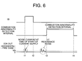
- FIG. 6 is a timing chart illustrating waveforms in respective portions of the internal combustion engine in Embodiment 4 of the present invention in a case of occurrence of combustion abnormality (accidental fire case).
- the current amplification factor control circuit 7 receives the ignition signal IB from the IB terminal through the ignition signal receiving terminal 7 c to detect whether or not the ignition signal is supplied, and sets, as a combustion abnormality detection interval, a predetermined interval between t 3 and t 4 after the ignition signal IB is blocked.
- the ion current is approximately 4 ⁇ A.
- the ion current detection signal ION-OUT transmitted to the ECU 20 is compared with a predetermined threshold Vth (corresponding to ion current of 4 ⁇ A) which is set in advance.
- Vth corresponding to ion current of 4 ⁇ A
- the current amplification factor control circuit 7 detects that an accidental fire occurs, and thus supplies a control signal from the current amplification factor control signal output terminal 7 b to the current amplification factor control terminal 6 c of the ion current detection circuit 6 so as to set the ion current amplification factor for amplifying the ion current detection signal ION-OUT to the high value (250 or more).
- the ion current detection circuit 6 sets the ion current amplification factor to the high value (250 or more) in response to the control signal.
- the precision of the ion current detection signal ION-OUT can be improved.
- the current equal to or larger than 1 mA can be supplied to the connection terminal portion between the ion current detection circuit 6 and the ECU 20 , whereby the electrical conductivity of the connection terminal portion between the ion current detection circuit 6 and the ECU 20 can be ensured.
- the ion current amplification factor for amplifying the ion current detection signal ION-OUT may be set to the low value (approximately 50).
- the current amplification factor control circuit 7 receives the ignition signal IB from the IB terminal through the ignition signal receiving terminal 7 c to detect the timing of supplying the ignition signal IB.
- the current amplification factor control circuit 7 supplies a control signal from the current amplification factor control signal output terminal 7 b to the current amplification factor control terminal 6 c of the ion current detection circuit 6 so as to set the ion current amplification factor for amplifying the ion current detection signal ION-OUT to the low value (approximately 50).
- the ion current detection circuit 6 sets the ion current amplification factor to the low value (approximately 50) in response to the control signal. Therefore, the ion current detection signal ION-OUT to be transmitted to the ECU 20 can be accurately transmitted to the ECU 20 without exceeding the dynamic range of the ECU 20 .
- the ion current amplification factor of the ion current detection circuit 6 is set such that the amplified ion current flowing between the ion current detection circuit 6 and the ECU 20 is equal to or larger than 1 mA.
- the connection terminal portion between the ion current detection circuit 6 and the ECU 20 can be supplied to the connection terminal portion between the ion current detection circuit 6 and the ECU 20 .
- the electrical conductivity of the connection terminal portion between the ion current detection circuit 6 and the ECU 20 can be ensured without using the conductive coating such as the coating plated with gold or silver for the connection terminal portion between the ion current detection circuit 6 and the ECU 20 .
Landscapes
- Engineering & Computer Science (AREA)
- Chemical & Material Sciences (AREA)
- Combustion & Propulsion (AREA)
- Mechanical Engineering (AREA)
- General Engineering & Computer Science (AREA)
- Signal Processing (AREA)
- Ignition Installations For Internal Combustion Engines (AREA)
Abstract
Description
Claims (9)
Applications Claiming Priority (2)
| Application Number | Priority Date | Filing Date | Title |
|---|---|---|---|
| JP2009-014274 | 2009-01-26 | ||
| JP2009014274A JP2010169063A (en) | 2009-01-26 | 2009-01-26 | Ion current detection device |
Publications (2)
| Publication Number | Publication Date |
|---|---|
| US20100186715A1 US20100186715A1 (en) | 2010-07-29 |
| US9470203B2 true US9470203B2 (en) | 2016-10-18 |
Family
ID=42353135
Family Applications (1)
| Application Number | Title | Priority Date | Filing Date |
|---|---|---|---|
| US12/506,010 Expired - Fee Related US9470203B2 (en) | 2009-01-26 | 2009-07-20 | Ion current detector |
Country Status (2)
| Country | Link |
|---|---|
| US (1) | US9470203B2 (en) |
| JP (1) | JP2010169063A (en) |
Families Citing this family (3)
| Publication number | Priority date | Publication date | Assignee | Title |
|---|---|---|---|---|
| JP2010106702A (en) * | 2008-10-29 | 2010-05-13 | Mitsubishi Electric Corp | Combustion state detector for internal combustion engine |
| CN104915531B (en) * | 2014-03-12 | 2018-02-02 | 北京理工大学 | The method and apparatus for analyzing ionic structure |
| CN107949699B (en) * | 2015-08-14 | 2021-02-05 | 密歇根州立大学董事会 | Ionization detector with spark plug coil short-circuited primary inductor |
Citations (12)
| Publication number | Priority date | Publication date | Assignee | Title |
|---|---|---|---|---|
| JPH1030541A (en) | 1996-07-11 | 1998-02-03 | Aisan Ind Co Ltd | Ignition device for internal combustion engine |
| US5834630A (en) * | 1997-02-19 | 1998-11-10 | Tanaka Scientific Limited | Apparatus for measuring flash point of article |
| US5970952A (en) * | 1997-06-25 | 1999-10-26 | Toyota Jidosha Kabushiki Kaisha | Combustion state detector apparatus for an internal combustion engine |
| JP2000240551A (en) | 1999-02-18 | 2000-09-05 | Mitsubishi Electric Corp | Ion current detector |
| US6328016B1 (en) * | 1999-09-20 | 2001-12-11 | Mitsubishi Denki Kabushiki Kaisha | Knock suppression control apparatus for internal combustion engine |
| US20030101797A1 (en) * | 2001-12-04 | 2003-06-05 | Mitsubishi Denki Kabushiki Kaisha | Misfire detection device for internal combustion engine |
| US6813933B1 (en) * | 1999-11-08 | 2004-11-09 | Robert Bosch Gmbh | Method and device for positioning measuring displays for measuring ion currents |
| JP3605962B2 (en) | 1996-09-20 | 2004-12-22 | 株式会社デンソー | Ion current detector |
| US20060158195A1 (en) * | 2005-01-14 | 2006-07-20 | Denso Corporation | Ion current detecting device in internal combustion engine |
| US7458250B2 (en) * | 2005-11-01 | 2008-12-02 | Phelon Euro Ab | Ion sensing arrangement for small gasoline engine |
| US7467626B2 (en) * | 2006-12-08 | 2008-12-23 | Mitsubishi Electric Corporation | Ignition device of ignition control system for an internal combustion engine |
| US8490598B2 (en) * | 2009-08-20 | 2013-07-23 | Ford Global Technologies, Llc | Ignition coil with ionization and digital feedback for an internal combustion engine |
-
2009
- 2009-01-26 JP JP2009014274A patent/JP2010169063A/en active Pending
- 2009-07-20 US US12/506,010 patent/US9470203B2/en not_active Expired - Fee Related
Patent Citations (14)
| Publication number | Priority date | Publication date | Assignee | Title |
|---|---|---|---|---|
| JPH1030541A (en) | 1996-07-11 | 1998-02-03 | Aisan Ind Co Ltd | Ignition device for internal combustion engine |
| JP3605962B2 (en) | 1996-09-20 | 2004-12-22 | 株式会社デンソー | Ion current detector |
| US5834630A (en) * | 1997-02-19 | 1998-11-10 | Tanaka Scientific Limited | Apparatus for measuring flash point of article |
| US5970952A (en) * | 1997-06-25 | 1999-10-26 | Toyota Jidosha Kabushiki Kaisha | Combustion state detector apparatus for an internal combustion engine |
| JP2000240551A (en) | 1999-02-18 | 2000-09-05 | Mitsubishi Electric Corp | Ion current detector |
| US6202474B1 (en) * | 1999-02-18 | 2001-03-20 | Mitsubishi Denki Kabushiki Kaisha | Ion current detector |
| US6328016B1 (en) * | 1999-09-20 | 2001-12-11 | Mitsubishi Denki Kabushiki Kaisha | Knock suppression control apparatus for internal combustion engine |
| US6813933B1 (en) * | 1999-11-08 | 2004-11-09 | Robert Bosch Gmbh | Method and device for positioning measuring displays for measuring ion currents |
| US20030101797A1 (en) * | 2001-12-04 | 2003-06-05 | Mitsubishi Denki Kabushiki Kaisha | Misfire detection device for internal combustion engine |
| US20060158195A1 (en) * | 2005-01-14 | 2006-07-20 | Denso Corporation | Ion current detecting device in internal combustion engine |
| US7164271B2 (en) * | 2005-01-14 | 2007-01-16 | Denso Corporation | Ion current detecting device in internal combustion engine |
| US7458250B2 (en) * | 2005-11-01 | 2008-12-02 | Phelon Euro Ab | Ion sensing arrangement for small gasoline engine |
| US7467626B2 (en) * | 2006-12-08 | 2008-12-23 | Mitsubishi Electric Corporation | Ignition device of ignition control system for an internal combustion engine |
| US8490598B2 (en) * | 2009-08-20 | 2013-07-23 | Ford Global Technologies, Llc | Ignition coil with ionization and digital feedback for an internal combustion engine |
Non-Patent Citations (1)
| Title |
|---|
| Communication from Japanese Patent Office dated Nov. 30, 2010. |
Also Published As
| Publication number | Publication date |
|---|---|
| JP2010169063A (en) | 2010-08-05 |
| US20100186715A1 (en) | 2010-07-29 |
Similar Documents
| Publication | Publication Date | Title |
|---|---|---|
| JP3971732B2 (en) | Circuit for measuring the ionization current in the combustion chamber of an internal combustion engine | |
| US7559319B2 (en) | Ignition coil apparatus for an internal combustion engine | |
| JP3192541B2 (en) | Misfire detection circuit for internal combustion engine | |
| US7467626B2 (en) | Ignition device of ignition control system for an internal combustion engine | |
| JPH11159430A (en) | Ion current detector for internal combustion engines | |
| JPH10252633A (en) | Ion current detector for internal combustion engines | |
| US20170141545A1 (en) | Method of forming an igniter circuit and structure therefor | |
| US9470203B2 (en) | Ion current detector | |
| US7581534B2 (en) | Internal combustion engine ignition device | |
| US7267115B2 (en) | Ignition apparatus for an internal combustion engine | |
| JP5802117B2 (en) | Ignition device and ignition system | |
| US6997171B1 (en) | Ignition apparatus for an internal combustion engine | |
| CN113195885B (en) | Ion current detection circuit, ignition control device and ignition system | |
| JP2017172588A (en) | Capacitive ignition system with ion-sensing and suppression of ac ringing | |
| US7164271B2 (en) | Ion current detecting device in internal combustion engine | |
| US20120013262A1 (en) | Ignition apparatus for plasma jet ignition plug and ignition system | |
| JP5410214B2 (en) | Ion current detector | |
| JP2014070507A (en) | Ignition device for internal combustion engine | |
| JP5347756B2 (en) | Ignition device and ion current detection system | |
| CN115968425A (en) | Electronic device and control system for ignition coil in internal combustion engine | |
| JP2015190396A (en) | Ion current detector for internal combustion engine | |
| US20220120251A1 (en) | Electronic device to control an ignition coil of an internal combustion engine and electronic ignition system thereof for detecting a misfire in the internal combustion engine | |
| US20220136477A1 (en) | Electronic device to control an ignition coil of an internal combustion engine and electronic ignition system thereof for detecting a pre-ignition in the internal combustion engine | |
| JP2014070505A (en) | Ion current detection device | |
| JPH08177703A (en) | Method for detecting combustion state by ion current |
Legal Events
| Date | Code | Title | Description |
|---|---|---|---|
| AS | Assignment |
Owner name: MITSUBISHI ELECTRIC CORPORATION, JAPAN Free format text: ASSIGNMENT OF ASSIGNORS INTEREST;ASSIGNORS:AIDA, FUTOSHI;TANAYA, KIMIHIKO;SIGNING DATES FROM 20090630 TO 20090702;REEL/FRAME:022983/0786 |
|
| ZAAA | Notice of allowance and fees due |
Free format text: ORIGINAL CODE: NOA |
|
| ZAAB | Notice of allowance mailed |
Free format text: ORIGINAL CODE: MN/=. |
|
| FEPP | Fee payment procedure |
Free format text: PAYOR NUMBER ASSIGNED (ORIGINAL EVENT CODE: ASPN); ENTITY STATUS OF PATENT OWNER: LARGE ENTITY |
|
| ZAAA | Notice of allowance and fees due |
Free format text: ORIGINAL CODE: NOA |
|
| ZAAB | Notice of allowance mailed |
Free format text: ORIGINAL CODE: MN/=. |
|
| STCF | Information on status: patent grant |
Free format text: PATENTED CASE |
|
| MAFP | Maintenance fee payment |
Free format text: PAYMENT OF MAINTENANCE FEE, 4TH YEAR, LARGE ENTITY (ORIGINAL EVENT CODE: M1551); ENTITY STATUS OF PATENT OWNER: LARGE ENTITY Year of fee payment: 4 |
|
| FEPP | Fee payment procedure |
Free format text: MAINTENANCE FEE REMINDER MAILED (ORIGINAL EVENT CODE: REM.); ENTITY STATUS OF PATENT OWNER: LARGE ENTITY |
|
| LAPS | Lapse for failure to pay maintenance fees |
Free format text: PATENT EXPIRED FOR FAILURE TO PAY MAINTENANCE FEES (ORIGINAL EVENT CODE: EXP.); ENTITY STATUS OF PATENT OWNER: LARGE ENTITY |
|
| STCH | Information on status: patent discontinuation |
Free format text: PATENT EXPIRED DUE TO NONPAYMENT OF MAINTENANCE FEES UNDER 37 CFR 1.362 |
|
| FP | Lapsed due to failure to pay maintenance fee |
Effective date: 20241018 |