US9469347B1 - Vehicles including a wheel well reinforcement member - Google Patents
Vehicles including a wheel well reinforcement member Download PDFInfo
- Publication number
- US9469347B1 US9469347B1 US14/793,006 US201514793006A US9469347B1 US 9469347 B1 US9469347 B1 US 9469347B1 US 201514793006 A US201514793006 A US 201514793006A US 9469347 B1 US9469347 B1 US 9469347B1
- Authority
- US
- United States
- Prior art keywords
- vehicle
- face
- rocker
- coupled
- reinforcement member
- Prior art date
- Legal status (The legal status is an assumption and is not a legal conclusion. Google has not performed a legal analysis and makes no representation as to the accuracy of the status listed.)
- Expired - Fee Related
Links
- 230000002787 reinforcement Effects 0.000 title claims abstract description 83
- 239000000725 suspension Substances 0.000 claims description 32
- 230000004888 barrier function Effects 0.000 claims description 5
- 238000000034 method Methods 0.000 description 6
- 238000010276 construction Methods 0.000 description 4
- 238000012986 modification Methods 0.000 description 2
- 230000004048 modification Effects 0.000 description 2
- 239000000853 adhesive Substances 0.000 description 1
- 230000001070 adhesive effect Effects 0.000 description 1
- 230000008859 change Effects 0.000 description 1
- 238000006243 chemical reaction Methods 0.000 description 1
- 239000002131 composite material Substances 0.000 description 1
- 230000008878 coupling Effects 0.000 description 1
- 238000010168 coupling process Methods 0.000 description 1
- 238000005859 coupling reaction Methods 0.000 description 1
- 230000000694 effects Effects 0.000 description 1
- 238000005242 forging Methods 0.000 description 1
- 238000005304 joining Methods 0.000 description 1
- 238000003754 machining Methods 0.000 description 1
- 239000000463 material Substances 0.000 description 1
- 238000005259 measurement Methods 0.000 description 1
- 229910052751 metal Inorganic materials 0.000 description 1
- 239000002184 metal Substances 0.000 description 1
- 150000002739 metals Chemical class 0.000 description 1
- 230000021715 photosynthesis, light harvesting Effects 0.000 description 1
- 230000004044 response Effects 0.000 description 1
- 238000003860 storage Methods 0.000 description 1
Images


Classifications
-
- B—PERFORMING OPERATIONS; TRANSPORTING
- B62—LAND VEHICLES FOR TRAVELLING OTHERWISE THAN ON RAILS
- B62D—MOTOR VEHICLES; TRAILERS
- B62D21/00—Understructures, i.e. chassis frame on which a vehicle body may be mounted
- B62D21/15—Understructures, i.e. chassis frame on which a vehicle body may be mounted having impact absorbing means, e.g. a frame designed to permanently or temporarily change shape or dimension upon impact with another body
- B62D21/152—Front or rear frames
- B62D21/155—Sub-frames or underguards
-
- B—PERFORMING OPERATIONS; TRANSPORTING
- B60—VEHICLES IN GENERAL
- B60R—VEHICLES, VEHICLE FITTINGS, OR VEHICLE PARTS, NOT OTHERWISE PROVIDED FOR
- B60R21/00—Arrangements or fittings on vehicles for protecting or preventing injuries to occupants or pedestrians in case of accidents or other traffic risks
-
- B—PERFORMING OPERATIONS; TRANSPORTING
- B62—LAND VEHICLES FOR TRAVELLING OTHERWISE THAN ON RAILS
- B62D—MOTOR VEHICLES; TRAILERS
- B62D21/00—Understructures, i.e. chassis frame on which a vehicle body may be mounted
- B62D21/15—Understructures, i.e. chassis frame on which a vehicle body may be mounted having impact absorbing means, e.g. a frame designed to permanently or temporarily change shape or dimension upon impact with another body
-
- B—PERFORMING OPERATIONS; TRANSPORTING
- B62—LAND VEHICLES FOR TRAVELLING OTHERWISE THAN ON RAILS
- B62D—MOTOR VEHICLES; TRAILERS
- B62D25/00—Superstructure or monocoque structure sub-units; Parts or details thereof not otherwise provided for
- B62D25/02—Side panels
- B62D25/025—Side sills thereof
-
- B—PERFORMING OPERATIONS; TRANSPORTING
- B62—LAND VEHICLES FOR TRAVELLING OTHERWISE THAN ON RAILS
- B62D—MOTOR VEHICLES; TRAILERS
- B62D25/00—Superstructure or monocoque structure sub-units; Parts or details thereof not otherwise provided for
- B62D25/04—Door pillars ; windshield pillars
-
- B—PERFORMING OPERATIONS; TRANSPORTING
- B62—LAND VEHICLES FOR TRAVELLING OTHERWISE THAN ON RAILS
- B62D—MOTOR VEHICLES; TRAILERS
- B62D27/00—Connections between superstructure or understructure sub-units
- B62D27/02—Connections between superstructure or understructure sub-units rigid
- B62D27/023—Assembly of structural joints
-
- B—PERFORMING OPERATIONS; TRANSPORTING
- B60—VEHICLES IN GENERAL
- B60R—VEHICLES, VEHICLE FITTINGS, OR VEHICLE PARTS, NOT OTHERWISE PROVIDED FOR
- B60R21/00—Arrangements or fittings on vehicles for protecting or preventing injuries to occupants or pedestrians in case of accidents or other traffic risks
- B60R2021/0002—Type of accident
- B60R2021/0004—Frontal collision
Definitions
- the present specification generally relates to vehicles, and more specifically, vehicles that include a wheel well reinforcement member.
- Vehicles may be equipped with bumper systems and impact protection structures that elastically and plastically deform to absorb energy in the event of an impact.
- a substantial portion of energy from an impact with a small front bumper overlap may be directed outboard of many of the energy absorbing structures of the vehicle. Because a substantial portion of the energy from the impact is directed into the bumper assembly at a position that is outboard of many of the energy absorbing structures of the vehicle, the energy from the impact may not be absorbed or may only be partially absorbed by those energy absorbing structures of the vehicle. The unabsorbed energy may be directed into a front suspension unit and transferred rearward along the vehicle as the front suspension unit contacts vehicle structures proximate to a passenger cabin of the vehicle.
- a vehicle in one embodiment, includes a wheel well including a radially inward facing side, a suspension unit including a wheel that is positioned at least partially within the wheel well, a rocker coupled to the wheel well, where the rocker extends rearward from the wheel well in a vehicle longitudinal direction, a torque box coupled to the rocker, where the torque box is positioned rearward from the wheel well in the vehicle longitudinal direction and where the torque box extends inboard from the rocker in a vehicle lateral direction that is transverse to the vehicle longitudinal direction, and a reinforcement member positioned at least partially within the wheel well, the reinforcement member including a forward face that is coupled the radially inward facing side of the wheel well, and at least one of a downward face that is coupled to and extends along the torque box and that is oriented to face downward in a vehicle vertical direction and an outboard face that is coupled to and extends along the rocker and that is oriented to face outboard in the vehicle lateral direction.
- a vehicle in another embodiment, includes a rocker that extends in a vehicle longitudinal direction, a forward pillar coupled to the rocker, where the forward pillar extends upward from the rocker in a vehicle vertical direction, a torque box that is coupled to the rocker, where the torque box extends inboard from the rocker in a vehicle lateral direction that is transverse to the vehicle longitudinal direction, and a reinforcement member including a forward face that extends along the forward pillar and that is oriented to face forward in the vehicle longitudinal direction, and at least one of a downward face that is coupled to and extends along the torque box and that is oriented to face downward in the vehicle vertical direction and an outboard face that is coupled to and extends along the rocker and that is oriented to face outboard in the vehicle lateral direction.
- a vehicle in yet another embodiment, includes a rocker that extends in a vehicle longitudinal direction, a forward pillar coupled to the rocker, where the forward pillar extends upward from the rocker in a vehicle vertical direction, and a reinforcement member including a forward face that is positioned forward of and spaced apart from the forward pillar such that a gap is positioned between the forward face and the forward pillar, and an outboard face that is coupled to the forward pillar and the rocker such that the gap is at least partially enclosed between the reinforcement member and the forward pillar.
- FIG. 1 schematically depicts a perspective view of a vehicle according to one or more embodiments shown or described herein;
- FIG. 2 schematically depicts a perspective view of a body of the vehicle of FIG. 1 according to one or more embodiments shown or described herein;
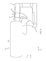
- FIG. 3 schematically depicts an enlarged perspective view of the body of FIG. 2 including a reinforcement member according to one or more embodiments shown or described herein;
- FIG. 4 schematically depicts a bottom view of the body and the reinforcement member of FIG. 3 according to one or more embodiments shown or described herein;
- FIG. 5 schematically depicts a side view of the body and the reinforcement member of FIG. 4 according to one or more embodiments shown or described herein;
- FIG. 6 schematically depicts a sectional view of the body and the reinforcement member of FIG. 5 along section 6 - 6 according to one or more embodiments shown or described herein;
- FIG. 7 schematically depicts a bottom view of the body and the reinforcement member of FIG. 4 during a small front bumper overlap impact according to one or more embodiments shown or described herein.
- Vehicles according to the present specification include a wheel well including a radially inward facing side, a suspension unit including a wheel that is positioned at least partially within the wheel well, and a rocker coupled to the wheel well, where the rocker extends rearward from the wheel well in a vehicle longitudinal direction.
- a torque box is coupled to the rocker. The torque box is positioned rearward from the wheel well in the vehicle longitudinal direction and where the torque box extends inboard from the rocker in a vehicle lateral direction that is transverse to the vehicle longitudinal direction.
- a reinforcement member positioned at least partially within the wheel well, the reinforcement member including a forward face that is coupled the radially inward facing side of the wheel well.
- the reinforcement member includes at least one of a downward face that is coupled to and extends along the torque box and that is oriented to face downward in a vehicle vertical direction and an outboard face that is coupled to and extends along the rocker and that is oriented to face outboard in the vehicle lateral direction.
- the vehicle includes a forward pillar, and the forward face of the reinforcement member extends along the forward pillar.
- the forward face of the reinforcement member is spaced apart from the forward pillar such that a gap is positioned between the forward face and the forward pillar.
- the reinforcement member may selectively absorb and direct forces and/or energy associated with a small front bumper overlap impact.
- vehicle longitudinal direction refers to the forward-rearward direction of the vehicle (i.e., in the +/ ⁇ vehicle X-direction as depicted).
- vehicle lateral direction refers to the cross-vehicle direction (i.e., in the +/ ⁇ vehicle Y-direction as depicted), and is transverse to the vehicle longitudinal direction.
- vehicle vertical direction refers to the upward-downward direction of the vehicle (i.e., in the +/ ⁇ vehicle Z-direction as depicted).
- inboard and outboard are used to describe the relative positioning of various components of the vehicle. Referring to FIG.
- the term “outboard” as used herein refers to the relative location of a component in direction 12 with respect to a vehicle centerline 10 .
- the term “inboard” as used herein refers to the relative location of a component in direction 14 with respect to the vehicle centerline 10 . Because the vehicle structures may be generally symmetrical about the vehicle centerline 10 , the direction to which use of the terms “inboard” and “outboard” refer may be mirrored about the vehicle centerline 10 when evaluating components positioned along opposite sides of the vehicle 100 .
- Motor vehicles that incorporate elements according to the present disclosure may include a variety of construction methodologies that are conventionally known, including the unibody construction methodology depicted in FIG. 1 as well as a body-on-frame construction methodology. While the embodiments of the present disclosure are described and depicted herein in with reference to unibody structures, it should be understood that vehicles that are constructed with body-on-frame construction may incorporate the elements that are shown and described herein. Furthermore, the Figures may only show one side of the vehicle. Descriptions of the other side of the vehicle may be omitted because both sides of the vehicle may be laterally symmetrical and substantially the same.
- the vehicle 100 includes a body 110 onto which a vehicle drivetrain is coupled.
- the vehicle 100 also includes a cabin 108 that is integral with the body 110 and a front bay 111 where a drive source (e.g., engine and/or electric motor) may be located.
- a drive source e.g., engine and/or electric motor
- the drive source may be positioned in a rear portion of the vehicle, and the front bay 111 may utilized as a storage compartment.
- the cabin 108 generally defines a passenger cabin of the vehicle 100 .
- a front suspension unit 102 may be coupled to the body 110 .
- the front suspension unit 102 may be coupled to a side support 112 ( FIG. 2 ) of the body 110 .
- the front suspension unit 102 may generally include vehicle components that connect the body 110 to a tire 106 .
- the front suspension unit 102 may include a wheel 104 that is surrounded by the tire 106 .
- the body 110 includes a wheel well 120 that is positioned at a front end of the vehicle 100 . At least a portion of the front suspension unit 102 may be positioned within the wheel well 120 .
- the wheel well 120 includes a radially-inward facing side 122 that may surround at least a portion of the wheel 104 and the tire 106 of the front suspension unit 102 .
- the body 110 includes a dash panel 118 that is positioned at a forward portion of the body 110 .
- the dash panel 118 extends in the vehicle lateral direction and the vehicle vertical direction to separate the front bay 111 ( FIG. 1 ) and the cabin 108 .
- the dash panel 118 may be integral with or may be coupled to the wheel well 120 .
- the body 110 includes a rocker 114 that extends rearward from the dash panel 118 in the vehicle longitudinal direction.
- the rocker 114 is coupled to the wheel well 120 and/or the dash panel 118 .
- the rocker 114 may be integral with the wheel well 120 and/or the dash panel 118 .
- the rocker 114 may extend between the wheel well 120 at the front portion of the vehicle 100 and a rear wheel well 124 at the rear portion of the vehicle 100 in the vehicle longitudinal direction.
- the pillars extend upward from the rocker 114 in the vehicle vertical direction.
- the pillars include a forward pillar 130 (e.g., an A-pillar and/or hinge pillar) that extends upward from the rocker 114 in the vehicle vertical direction.
- the vehicle may also include a center pillar 132 and/or a rear pillar 134 (e.g., a B-pillar and/or a C-pillar) positioned rearward from the forward pillar 130 in the vehicle longitudinal direction.
- the forward pillar 130 , the center pillar 132 , and/or the rear pillar 134 may support a roof 135 ( FIG. 1 ) of the vehicle 100 .
- the forward pillar 130 , the center pillar 132 , and the rear pillar 134 may be integral with the rocker 114 or may be coupled to the rocker 114 .
- the body 110 further includes the side support 112 that extends in the vehicle longitudinal direction.
- the side support 112 is positioned inboard of and spaced apart from the rocker 114 in the vehicle lateral direction. As described above, the side support 112 may be coupled to the front suspension unit 102 .
- the side support 112 may form a portion of a floor 113 of the cabin 108 .
- the body 110 further includes a torque box 116 positioned between the side support 112 and the rocker 114 in the vehicle lateral direction.
- the torque box 116 spans between the side support 112 and the rocker 114 in the vehicle lateral direction and is coupled to both the side support 112 and the rocker 114 .
- the torque box 116 is integral with the side support 112 and/or the rocker 114 .
- the torque box 116 may be integral with one of the side support 112 and the rocker 114 , and may be coupled to the other of the side support 112 and the rocker 114 .
- the torque box 116 provides lateral structural rigidity to the body 110 to counteract stresses generated by torque from the drive source during operation of the vehicle.
- the side support 112 , the rocker 114 , and the torque box 116 may be positioned rearward from and/or may form a portion of the wheel well 120 and/or the dash panel 118 of the vehicle 100 .
- the side support 112 , the rocker 114 , and the torque box 116 may form a portion of the radially-inward facing side 122 of the wheel well 120 .
- the vehicle 100 includes a reinforcement member 140 that is coupled to the body 110 of the vehicle 100 .
- the reinforcement member 140 is positioned such that at least a portion of the reinforcement member 140 is positioned within the wheel well 120 of the vehicle 100 .
- the reinforcement member 140 may be formed from a variety of materials including, for example and without limitation, metals, composites, and the like, and may be formed by any suitable method or combination of methods such as stamping, forging, machining, and the like.
- the reinforcement member may be coupled to various components of the body 110 through a variety of joining techniques, including, but not limited to, a welded attachment, a brazed attachment, mechanical fasteners, and/or structural adhesives.
- the reinforcement member 140 includes a forward face 142 that is oriented to face forward in the vehicle longitudinal direction.
- the forward face 142 may extend upward from the rocker 114 along the forward pillar 130 .
- the forward face 142 of the reinforcement member 140 may extend inboard of the rocker 114 , such that at least a portion of the forward face 142 extends across the torque box 116 in the vehicle lateral direction.
- the forward face 142 of the reinforcement member 140 may be coupled to the torque box 116 and/or the forward pillar 130 .
- the reinforcement member 140 may include an outboard face 144 that is oriented to face outboard in the vehicle lateral direction.
- the outboard face 144 may face in a direction that is substantially orthogonal to the forward face 142 of the reinforcement member 140 .
- the outboard face 144 extends rearward from the forward face 142 of the reinforcement member 140 .
- the outboard face 144 extends upward from the rocker 114 in the vehicle vertical direction along the forward pillar 130 .
- the outboard face 144 may be coupled to the forward pillar 130 and/or the rocker 114 .
- the reinforcement member 140 may include a downward face 146 that is oriented to face downward in the vehicle vertical direction.
- the downward face 146 may be oriented to face in a direction that is substantially orthogonal to the forward face 142 and the outboard face 144 of the reinforcement member 140 .
- the downward face 146 extends inboard from outboard face 144 of the reinforcement member 140 across the torque box 116 in the vehicle lateral direction.
- the downward face 146 may be coupled to the forward pillar 130 and/or the torque box 116 .
- the reinforcement member 140 may be coupled to the forward pillar 130 , the torque box 116 , and/or the rocker 114 .
- the reinforcement member 140 may distribute energy and/or forces associated with the impact among the forward pillar 130 , the torque box 116 , and/or the rocker 114 .
- the reinforcement member 140 may be coupled to the forward pillar 130 , the torque box 116 , and/or the rocker 114 , the reinforcement member 140 may provide structure in addition to the forward pillar 130 , the torque box 116 , and/or the rocker 114 .
- the reinforcement member 140 may increase the strength and/or stiffness of the forward pillar 130 , the torque box 116 , and/or the rocker 114 at positions proximate to the reinforcement member 140 as compared to a body 110 that does not include a reinforcement member 140 .
- the reinforcement member 140 may absorb and direct energy and/or forces associated with a small front bumper overlap impact.
- the reinforcement member 140 is positioned rearward of the front suspension unit 102 in the vehicle longitudinal direction.
- the reinforcement member 140 may absorb and direct energy and/or forces associated with a small front bumper overlap impact resulting from rearward translation of the front suspension unit 102 .
- the reinforcement member 140 includes the forward face 142 and the outboard face 144 . At least a portion of the forward face 142 and the outboard face 144 of the reinforcement member 140 are detached and spaced apart from the forward pillar 130 in the vehicle longitudinal direction and the vehicle lateral direction, respectively.
- the forward face 142 and the outboard face 144 are positioned forward and outboard of the forward pillar 130 such that a gap 150 is positioned between the forward pillar 130 and the reinforcement member 140 .
- the forward face 142 and the outboard face 144 may at least partially enclose the gap 150 in the vehicle longitudinal and the vehicle lateral directions.
- a septum member 148 may extend between the forward pillar 130 and the forward face 142 of the reinforcement member 140 in the vehicle longitudinal direction across the gap 150 .
- the septum member 148 may extend between the forward pillar 130 and the outboard face 144 in the vehicle lateral direction across the gap 150 .
- the septum member 148 may divide the gap 150 into a first lumen 152 and a second lumen 154 .
- the wheel 104 of the front suspension unit 102 may contact the reinforcement member 140 , causing the reinforcement member 140 to selectively deform and translate rearward in the vehicle longitudinal direction.
- the gap 150 and/or the first lumen 152 and the second lumen 154 may collapse in the vehicle longitudinal direction, which may absorb energy associated with the impact.
- vehicle structures When a vehicle impacts a barrier, vehicle structures may elastically and plastically deform to absorb energy while slowing the vehicle from its previous operating speed.
- the vehicle structures divert and absorb the energy associated with the moving vehicle into energy that deforms the vehicle structures.
- the vehicle structures may be designed to accommodate the introduction of the energy of the impact, such that the energy associated with the impact may be controllably dissipated and directed through selective and preferential deformation of the vehicle structures.
- the front corner of the vehicle may impact an object in what is referred to herein as a small front bumper overlap or a small overlap impact.
- a small front bumper overlap impact the impact occurs at an outboard portion of the vehicle (evaluated in a vehicle lateral direction), and only a portion of the front bumper strikes the object.
- some of the energy dissipation elements of the vehicle may not be initiated or may be only partially initiated.
- the energy that is introduced to the vehicle structures may be non-symmetrical when evaluated in the vehicle lateral direction. Accordingly, the reaction of the vehicle structures to the energy introduced by the small overlap impacts may introduce a non-symmetrical response to the vehicle structures.
- the structural members of the body 110 for example, may be non-symmetrically loaded when the vehicle is involved in a small overlap impact.
- all of the energy absorbing structures associated with the front bumper may have a reduced effect on the dissipation of energy of the impact.
- some of the energy absorbing structures associated with the bumper assembly of the vehicle 100 may not be activated or may be only partially activated, such that a portion of the energy absorbing structure of the vehicle may not dissipate energy associated with the small front bumper overlap impact. Instead, the energy and/or forces associated with the impact may be directed into the front suspension unit 102 of the vehicle 100 proximate to the barrier that the vehicle impacts.
- the front suspension unit 102 may translate rearward in the vehicle longitudinal direction and may contact the cabin 108 of the vehicle, transmitting energy and/or forces associated with the impact into the cabin 108 of the vehicle 100 .
- a barrier 200 including a vehicle-facing surface 202 may impact the body 110 of the vehicle 100 in a small front bumper overlap impact.
- energy associated with the impact may cause the front suspension unit 102 including the wheel 104 to deform and translate rearward in the vehicle longitudinal direction.
- the wheel 104 of the front suspension unit 102 deforms and translates rearward in the vehicle longitudinal direction, the wheel 104 may contact the reinforcement member 140 .
- the reinforcement member 140 may be coupled to and may increase a strength and/or stiffness of the forward pillar 130 , the rocker 114 , and/or the torque box 116 at positions proximate to the reinforcement member 140 .
- the reinforcement member 140 may direct forces and/or energy associated with the impact.
- the reinforcement member 140 may resist forces and/or energy associated with the impact that are directed rearward in the vehicle longitudinal direction as a result of contact between the wheel 104 and the reinforcement member 140 .
- the reinforcement member 140 may resist forces and/or energy associated with the impact that are directed rearward in the vehicle longitudinal direction, the reinforcement member 140 may encourage the wheel 104 and the front suspension unit 102 to deflect outboard and away from the body 110 of the vehicle 100 during the impact.
- the wheel 104 and the front suspension unit 102 may impart less force and/or energy associated with the impact to the body 110 as compared to impact configurations in which the wheel 104 and the front suspension unit 102 deform and translate in a generally rearward direction, which may thereby reduce intrusion of the front suspension unit 102 into the cabin 108 of the vehicle.
- vehicles according to the present disclosure include a reinforcement member that includes a forward face, and at least one of a downward face and an outboard face.
- the forward face, the downward face, and the outboard face may be coupled to a rocker, a forward pillar, and/or a torque box of the vehicle, and may increase the strength and/or stiffness of the rocker, the forward pillar, and/or the torque box proximate to the reinforcement member.
- the reinforcement member may absorb and direct energy and/or forces associated with a small front bumper overlap impact.
- the forward face and the outboard face of the reinforcement member may be spaced apart from the forward pillar, and a gap may be positioned between the forward pillar and the forward face and the outboard face of the reinforcement member.
Landscapes
- Engineering & Computer Science (AREA)
- Mechanical Engineering (AREA)
- Chemical & Material Sciences (AREA)
- Combustion & Propulsion (AREA)
- Transportation (AREA)
- Body Structure For Vehicles (AREA)
Abstract
Description
Claims (13)
Priority Applications (1)
| Application Number | Priority Date | Filing Date | Title |
|---|---|---|---|
| US14/793,006 US9469347B1 (en) | 2015-07-07 | 2015-07-07 | Vehicles including a wheel well reinforcement member |
Applications Claiming Priority (1)
| Application Number | Priority Date | Filing Date | Title |
|---|---|---|---|
| US14/793,006 US9469347B1 (en) | 2015-07-07 | 2015-07-07 | Vehicles including a wheel well reinforcement member |
Publications (1)
| Publication Number | Publication Date |
|---|---|
| US9469347B1 true US9469347B1 (en) | 2016-10-18 |
Family
ID=57120416
Family Applications (1)
| Application Number | Title | Priority Date | Filing Date |
|---|---|---|---|
| US14/793,006 Expired - Fee Related US9469347B1 (en) | 2015-07-07 | 2015-07-07 | Vehicles including a wheel well reinforcement member |
Country Status (1)
| Country | Link |
|---|---|
| US (1) | US9469347B1 (en) |
Cited By (6)
| Publication number | Priority date | Publication date | Assignee | Title |
|---|---|---|---|---|
| US20160016612A1 (en) * | 2014-07-18 | 2016-01-21 | Toyota Jidosha Kyushu Kabushiki Kaisha | Vehicle front part structure |
| US20160052552A1 (en) * | 2013-03-26 | 2016-02-25 | Toyota Jidosha Kabushiki Kaisha | Vehicle body side structure of automobile |
| US10077014B1 (en) * | 2017-03-20 | 2018-09-18 | GM Global Technology Operations LLC | Body-mounted tire blocker assembly |
| US11091202B2 (en) | 2019-05-07 | 2021-08-17 | Ford Global Technologies, Llc | Chassis brace and small offset rigid barrier reinforcement assembly |
| US11440591B2 (en) * | 2018-10-09 | 2022-09-13 | Toyota Jidosha Kabushiki Kaisha | Vehicle body structure of convertible vehicle |
| EP4344985A1 (en) * | 2022-09-28 | 2024-04-03 | Ningbo Geely Automobile Research & Development Co. Ltd. | A vehicle having an energy absorbing arrangement |
Citations (15)
| Publication number | Priority date | Publication date | Assignee | Title |
|---|---|---|---|---|
| US5042872A (en) * | 1988-07-30 | 1991-08-27 | Mazda Motor Corporation | Pillar structure for front body portion of automobile |
| US5653495A (en) | 1992-09-11 | 1997-08-05 | Saab Automobile Aktiebolag | Reinforced door aperture frame for reducing deformation from offset collisions |
| US6364358B1 (en) | 2000-03-21 | 2002-04-02 | Honda Giken Kogyo Kabushiki Kaisha | Side sill load path initiator |
| US6447052B2 (en) | 2000-03-10 | 2002-09-10 | Nissan Motor Co., Ltd. | Body structure for vehicle |
| US6866115B2 (en) | 2001-02-27 | 2005-03-15 | Nissan Motor Co., Ltd. | Front body structure for vehicle |
| US20090195019A1 (en) * | 2008-02-01 | 2009-08-06 | Honda Motor Co., Ltd. | Automotive vehicle body structure |
| US7735870B2 (en) | 2005-02-22 | 2010-06-15 | Toyota Jidosha Kabushiki Kaisha | Front structure of vehicle body |
| US8029050B2 (en) | 2006-10-25 | 2011-10-04 | Toyota Jidosha Kabushiki Kaisha | Vehicle front structure |
| US8371643B2 (en) | 2009-05-19 | 2013-02-12 | Suzuki Motor Corporation | Lower structure of vehicle front pillars |
| US8469442B1 (en) | 2012-06-27 | 2013-06-25 | Nissan North America, Inc. | Vehicle front body structure |
| US20130285414A1 (en) | 2012-04-25 | 2013-10-31 | Ford Global Technologies, Llc | Automatic vehicle stiffened pillar assembly |
| US20140232136A1 (en) | 2013-02-20 | 2014-08-21 | Dr. Ing. H.C. F. Porsche Aktiengesellschaft | Motor vehicle support structure |
| US20150246692A1 (en) * | 2014-03-03 | 2015-09-03 | Honda Motor Co., Ltd. | Front pillar construction having reinforcement member for vehicle frame |
| US20160039466A1 (en) * | 2013-03-26 | 2016-02-11 | Toyota Jidosha Kabushiki Kaisha | Automobile front pillar lower structure |
| US20160052554A1 (en) * | 2014-08-21 | 2016-02-25 | Toyota Jidosha Kabushiki Kaisha | Vehicle body front section structure |
-
2015
- 2015-07-07 US US14/793,006 patent/US9469347B1/en not_active Expired - Fee Related
Patent Citations (16)
| Publication number | Priority date | Publication date | Assignee | Title |
|---|---|---|---|---|
| US5042872A (en) * | 1988-07-30 | 1991-08-27 | Mazda Motor Corporation | Pillar structure for front body portion of automobile |
| US5653495A (en) | 1992-09-11 | 1997-08-05 | Saab Automobile Aktiebolag | Reinforced door aperture frame for reducing deformation from offset collisions |
| US6447052B2 (en) | 2000-03-10 | 2002-09-10 | Nissan Motor Co., Ltd. | Body structure for vehicle |
| US6364358B1 (en) | 2000-03-21 | 2002-04-02 | Honda Giken Kogyo Kabushiki Kaisha | Side sill load path initiator |
| US6866115B2 (en) | 2001-02-27 | 2005-03-15 | Nissan Motor Co., Ltd. | Front body structure for vehicle |
| US7735870B2 (en) | 2005-02-22 | 2010-06-15 | Toyota Jidosha Kabushiki Kaisha | Front structure of vehicle body |
| US8029050B2 (en) | 2006-10-25 | 2011-10-04 | Toyota Jidosha Kabushiki Kaisha | Vehicle front structure |
| US20090195019A1 (en) * | 2008-02-01 | 2009-08-06 | Honda Motor Co., Ltd. | Automotive vehicle body structure |
| US8371643B2 (en) | 2009-05-19 | 2013-02-12 | Suzuki Motor Corporation | Lower structure of vehicle front pillars |
| US20130285414A1 (en) | 2012-04-25 | 2013-10-31 | Ford Global Technologies, Llc | Automatic vehicle stiffened pillar assembly |
| US8469442B1 (en) | 2012-06-27 | 2013-06-25 | Nissan North America, Inc. | Vehicle front body structure |
| US20140232136A1 (en) | 2013-02-20 | 2014-08-21 | Dr. Ing. H.C. F. Porsche Aktiengesellschaft | Motor vehicle support structure |
| US20160039466A1 (en) * | 2013-03-26 | 2016-02-11 | Toyota Jidosha Kabushiki Kaisha | Automobile front pillar lower structure |
| US20150246692A1 (en) * | 2014-03-03 | 2015-09-03 | Honda Motor Co., Ltd. | Front pillar construction having reinforcement member for vehicle frame |
| US9187133B2 (en) * | 2014-03-03 | 2015-11-17 | Honda Motor Co., Ltd. | Front pillar construction having reinforcement member for vehicle frame |
| US20160052554A1 (en) * | 2014-08-21 | 2016-02-25 | Toyota Jidosha Kabushiki Kaisha | Vehicle body front section structure |
Cited By (9)
| Publication number | Priority date | Publication date | Assignee | Title |
|---|---|---|---|---|
| US20160052552A1 (en) * | 2013-03-26 | 2016-02-25 | Toyota Jidosha Kabushiki Kaisha | Vehicle body side structure of automobile |
| US9988087B2 (en) * | 2013-03-26 | 2018-06-05 | Toyota Jidosha Kabushiki Kaisha | Vehicle body side structure of automobile |
| US20160016612A1 (en) * | 2014-07-18 | 2016-01-21 | Toyota Jidosha Kyushu Kabushiki Kaisha | Vehicle front part structure |
| US9821853B2 (en) * | 2014-07-18 | 2017-11-21 | Toyota Jidosha Kyushu Kabushiki Kaisha | Vehicle front part structure |
| US10077014B1 (en) * | 2017-03-20 | 2018-09-18 | GM Global Technology Operations LLC | Body-mounted tire blocker assembly |
| US11440591B2 (en) * | 2018-10-09 | 2022-09-13 | Toyota Jidosha Kabushiki Kaisha | Vehicle body structure of convertible vehicle |
| US11091202B2 (en) | 2019-05-07 | 2021-08-17 | Ford Global Technologies, Llc | Chassis brace and small offset rigid barrier reinforcement assembly |
| EP4344985A1 (en) * | 2022-09-28 | 2024-04-03 | Ningbo Geely Automobile Research & Development Co. Ltd. | A vehicle having an energy absorbing arrangement |
| WO2024067119A1 (en) * | 2022-09-28 | 2024-04-04 | Ningbo Geely Automobile Research & Development Co., Ltd. | A vehicle having an energy absorbing arrangement |
Similar Documents
| Publication | Publication Date | Title |
|---|---|---|
| US9315167B1 (en) | Bumpers including a reinforcement bracket and vehicles incorporating the same | |
| US9371093B1 (en) | Vehicles having upper side member reinforcement portions | |
| US9616935B2 (en) | Vehicle structures and methods of assembling the same | |
| US9381949B2 (en) | Vehicles having a cross-vehicle stabilizing structure | |
| US9469347B1 (en) | Vehicles including a wheel well reinforcement member | |
| US9669785B2 (en) | Bumper assemblies including spacer members and vehicles incorporating the same | |
| US9296427B1 (en) | Vehicles including targeted energy absorption structures | |
| US9527464B2 (en) | Bumpers including a reinforcement bracket and vehicles incorporating the same | |
| US9233715B1 (en) | Bumper assemblies including spacer members and vehicles incorporating the same | |
| JP5858006B2 (en) | Auto body front structure | |
| US9242675B2 (en) | Automobile vehicle-body front structure | |
| US9527463B2 (en) | Bumper assemblies including spacer members and vehicles incorporating the same | |
| EP2815953A1 (en) | Vehicle body bottom structure | |
| JP4384206B2 (en) | Auto body structure | |
| US8939496B2 (en) | Vehicle structure | |
| US10676135B2 (en) | Front vehicle body reinforcing structure | |
| CN107074296B (en) | Support device for the front compartment of a passenger car and a passenger car | |
| US9266567B1 (en) | Vehicles having a dash panel reinforcement gusset | |
| US9090291B1 (en) | Front pillar assemblies with front pillar lower reinforcement members having lower wrap reinforcement structures | |
| US20130285414A1 (en) | Automatic vehicle stiffened pillar assembly | |
| US9302715B2 (en) | Vehicles having side support reinforcement gussets | |
| US9238487B1 (en) | Inner front side member to rocker support reinforcement gussets for vehicle front structures | |
| CN112714737B (en) | Vehicle body lower structure | |
| JP4923004B2 (en) | Auto body front structure | |
| US9815497B1 (en) | Vehicles including an engine compartment spacer member |
Legal Events
| Date | Code | Title | Description |
|---|---|---|---|
| AS | Assignment |
Owner name: TOYOTA MOTOR ENGINEERING & MANUFACTURING NORTH AME Free format text: ASSIGNMENT OF ASSIGNORS INTEREST;ASSIGNORS:SCHNUG, TYLER E.;ZHU, MIN;SIGNING DATES FROM 20150618 TO 20150629;REEL/FRAME:036009/0039 |
|
| STCF | Information on status: patent grant |
Free format text: PATENTED CASE |
|
| AS | Assignment |
Owner name: TOYOTA JIDOSHA KABUSHIKI KAISHA, JAPAN Free format text: ASSIGNMENT OF ASSIGNORS INTEREST;ASSIGNOR:TOYOTA MOTOR ENGINEERING & MANUFACTURING NORTH AMERICA, INC.;REEL/FRAME:040057/0805 Effective date: 20161013 |
|
| MAFP | Maintenance fee payment |
Free format text: PAYMENT OF MAINTENANCE FEE, 4TH YEAR, LARGE ENTITY (ORIGINAL EVENT CODE: M1551); ENTITY STATUS OF PATENT OWNER: LARGE ENTITY Year of fee payment: 4 |
|
| FEPP | Fee payment procedure |
Free format text: MAINTENANCE FEE REMINDER MAILED (ORIGINAL EVENT CODE: REM.); ENTITY STATUS OF PATENT OWNER: LARGE ENTITY |
|
| LAPS | Lapse for failure to pay maintenance fees |
Free format text: PATENT EXPIRED FOR FAILURE TO PAY MAINTENANCE FEES (ORIGINAL EVENT CODE: EXP.); ENTITY STATUS OF PATENT OWNER: LARGE ENTITY |
|
| STCH | Information on status: patent discontinuation |
Free format text: PATENT EXPIRED DUE TO NONPAYMENT OF MAINTENANCE FEES UNDER 37 CFR 1.362 |
|
| FP | Lapsed due to failure to pay maintenance fee |
Effective date: 20241018 |