US9468533B2 - Method of reconstructing a patient's wrist - Google Patents
Method of reconstructing a patient's wrist Download PDFInfo
- Publication number
- US9468533B2 US9468533B2 US14/289,140 US201414289140A US9468533B2 US 9468533 B2 US9468533 B2 US 9468533B2 US 201414289140 A US201414289140 A US 201414289140A US 9468533 B2 US9468533 B2 US 9468533B2
- Authority
- US
- United States
- Prior art keywords
- patient
- carpal
- proximal
- carpal bones
- bones
- Prior art date
- Legal status (The legal status is an assumption and is not a legal conclusion. Google has not performed a legal analysis and makes no representation as to the accuracy of the status listed.)
- Active
Links
Images


Classifications
-
- A—HUMAN NECESSITIES
- A61—MEDICAL OR VETERINARY SCIENCE; HYGIENE
- A61F—FILTERS IMPLANTABLE INTO BLOOD VESSELS; PROSTHESES; DEVICES PROVIDING PATENCY TO, OR PREVENTING COLLAPSING OF, TUBULAR STRUCTURES OF THE BODY, e.g. STENTS; ORTHOPAEDIC, NURSING OR CONTRACEPTIVE DEVICES; FOMENTATION; TREATMENT OR PROTECTION OF EYES OR EARS; BANDAGES, DRESSINGS OR ABSORBENT PADS; FIRST-AID KITS
- A61F2/00—Filters implantable into blood vessels; Prostheses, i.e. artificial substitutes or replacements for parts of the body; Appliances for connecting them with the body; Devices providing patency to, or preventing collapsing of, tubular structures of the body, e.g. stents
- A61F2/02—Prostheses implantable into the body
- A61F2/30—Joints
- A61F2/42—Joints for wrists or ankles; for hands, e.g. fingers; for feet, e.g. toes
- A61F2/4261—Joints for wrists or ankles; for hands, e.g. fingers; for feet, e.g. toes for wrists
-
- A—HUMAN NECESSITIES
- A61—MEDICAL OR VETERINARY SCIENCE; HYGIENE
- A61F—FILTERS IMPLANTABLE INTO BLOOD VESSELS; PROSTHESES; DEVICES PROVIDING PATENCY TO, OR PREVENTING COLLAPSING OF, TUBULAR STRUCTURES OF THE BODY, e.g. STENTS; ORTHOPAEDIC, NURSING OR CONTRACEPTIVE DEVICES; FOMENTATION; TREATMENT OR PROTECTION OF EYES OR EARS; BANDAGES, DRESSINGS OR ABSORBENT PADS; FIRST-AID KITS
- A61F2/00—Filters implantable into blood vessels; Prostheses, i.e. artificial substitutes or replacements for parts of the body; Appliances for connecting them with the body; Devices providing patency to, or preventing collapsing of, tubular structures of the body, e.g. stents
- A61F2/02—Prostheses implantable into the body
- A61F2/30—Joints
- A61F2002/30001—Additional features of subject-matter classified in A61F2/28, A61F2/30 and subgroups thereof
- A61F2002/30108—Shapes
- A61F2002/3011—Cross-sections or two-dimensional shapes
- A61F2002/30112—Rounded shapes, e.g. with rounded corners
- A61F2002/30131—Rounded shapes, e.g. with rounded corners horseshoe- or crescent- or C-shaped or U-shaped
-
- A—HUMAN NECESSITIES
- A61—MEDICAL OR VETERINARY SCIENCE; HYGIENE
- A61F—FILTERS IMPLANTABLE INTO BLOOD VESSELS; PROSTHESES; DEVICES PROVIDING PATENCY TO, OR PREVENTING COLLAPSING OF, TUBULAR STRUCTURES OF THE BODY, e.g. STENTS; ORTHOPAEDIC, NURSING OR CONTRACEPTIVE DEVICES; FOMENTATION; TREATMENT OR PROTECTION OF EYES OR EARS; BANDAGES, DRESSINGS OR ABSORBENT PADS; FIRST-AID KITS
- A61F2/00—Filters implantable into blood vessels; Prostheses, i.e. artificial substitutes or replacements for parts of the body; Appliances for connecting them with the body; Devices providing patency to, or preventing collapsing of, tubular structures of the body, e.g. stents
- A61F2/02—Prostheses implantable into the body
- A61F2/30—Joints
- A61F2002/30001—Additional features of subject-matter classified in A61F2/28, A61F2/30 and subgroups thereof
- A61F2002/30316—The prosthesis having different structural features at different locations within the same prosthesis; Connections between prosthetic parts; Special structural features of bone or joint prostheses not otherwise provided for
- A61F2002/30317—The prosthesis having different structural features at different locations within the same prosthesis
- A61F2002/30327—The prosthesis having different structural features at different locations within the same prosthesis differing in diameter
-
- A—HUMAN NECESSITIES
- A61—MEDICAL OR VETERINARY SCIENCE; HYGIENE
- A61F—FILTERS IMPLANTABLE INTO BLOOD VESSELS; PROSTHESES; DEVICES PROVIDING PATENCY TO, OR PREVENTING COLLAPSING OF, TUBULAR STRUCTURES OF THE BODY, e.g. STENTS; ORTHOPAEDIC, NURSING OR CONTRACEPTIVE DEVICES; FOMENTATION; TREATMENT OR PROTECTION OF EYES OR EARS; BANDAGES, DRESSINGS OR ABSORBENT PADS; FIRST-AID KITS
- A61F2/00—Filters implantable into blood vessels; Prostheses, i.e. artificial substitutes or replacements for parts of the body; Appliances for connecting them with the body; Devices providing patency to, or preventing collapsing of, tubular structures of the body, e.g. stents
- A61F2/02—Prostheses implantable into the body
- A61F2/30—Joints
- A61F2002/30001—Additional features of subject-matter classified in A61F2/28, A61F2/30 and subgroups thereof
- A61F2002/30316—The prosthesis having different structural features at different locations within the same prosthesis; Connections between prosthetic parts; Special structural features of bone or joint prostheses not otherwise provided for
- A61F2002/30535—Special structural features of bone or joint prostheses not otherwise provided for
- A61F2002/30576—Special structural features of bone or joint prostheses not otherwise provided for with extending fixation tabs
- A61F2002/30578—Special structural features of bone or joint prostheses not otherwise provided for with extending fixation tabs having apertures, e.g. for receiving fixation screws
-
- A—HUMAN NECESSITIES
- A61—MEDICAL OR VETERINARY SCIENCE; HYGIENE
- A61F—FILTERS IMPLANTABLE INTO BLOOD VESSELS; PROSTHESES; DEVICES PROVIDING PATENCY TO, OR PREVENTING COLLAPSING OF, TUBULAR STRUCTURES OF THE BODY, e.g. STENTS; ORTHOPAEDIC, NURSING OR CONTRACEPTIVE DEVICES; FOMENTATION; TREATMENT OR PROTECTION OF EYES OR EARS; BANDAGES, DRESSINGS OR ABSORBENT PADS; FIRST-AID KITS
- A61F2/00—Filters implantable into blood vessels; Prostheses, i.e. artificial substitutes or replacements for parts of the body; Appliances for connecting them with the body; Devices providing patency to, or preventing collapsing of, tubular structures of the body, e.g. stents
- A61F2/02—Prostheses implantable into the body
- A61F2/30—Joints
- A61F2002/30001—Additional features of subject-matter classified in A61F2/28, A61F2/30 and subgroups thereof
- A61F2002/30621—Features concerning the anatomical functioning or articulation of the prosthetic joint
- A61F2002/30622—Implant for fusing a joint or bone material
-
- A—HUMAN NECESSITIES
- A61—MEDICAL OR VETERINARY SCIENCE; HYGIENE
- A61F—FILTERS IMPLANTABLE INTO BLOOD VESSELS; PROSTHESES; DEVICES PROVIDING PATENCY TO, OR PREVENTING COLLAPSING OF, TUBULAR STRUCTURES OF THE BODY, e.g. STENTS; ORTHOPAEDIC, NURSING OR CONTRACEPTIVE DEVICES; FOMENTATION; TREATMENT OR PROTECTION OF EYES OR EARS; BANDAGES, DRESSINGS OR ABSORBENT PADS; FIRST-AID KITS
- A61F2/00—Filters implantable into blood vessels; Prostheses, i.e. artificial substitutes or replacements for parts of the body; Appliances for connecting them with the body; Devices providing patency to, or preventing collapsing of, tubular structures of the body, e.g. stents
- A61F2/02—Prostheses implantable into the body
- A61F2/30—Joints
- A61F2/30767—Special external or bone-contacting surface, e.g. coating for improving bone ingrowth
- A61F2/30771—Special external or bone-contacting surface, e.g. coating for improving bone ingrowth applied in original prostheses, e.g. holes or grooves
- A61F2002/30772—Apertures or holes, e.g. of circular cross section
-
- A—HUMAN NECESSITIES
- A61—MEDICAL OR VETERINARY SCIENCE; HYGIENE
- A61F—FILTERS IMPLANTABLE INTO BLOOD VESSELS; PROSTHESES; DEVICES PROVIDING PATENCY TO, OR PREVENTING COLLAPSING OF, TUBULAR STRUCTURES OF THE BODY, e.g. STENTS; ORTHOPAEDIC, NURSING OR CONTRACEPTIVE DEVICES; FOMENTATION; TREATMENT OR PROTECTION OF EYES OR EARS; BANDAGES, DRESSINGS OR ABSORBENT PADS; FIRST-AID KITS
- A61F2/00—Filters implantable into blood vessels; Prostheses, i.e. artificial substitutes or replacements for parts of the body; Appliances for connecting them with the body; Devices providing patency to, or preventing collapsing of, tubular structures of the body, e.g. stents
- A61F2/02—Prostheses implantable into the body
- A61F2/30—Joints
- A61F2/30767—Special external or bone-contacting surface, e.g. coating for improving bone ingrowth
- A61F2002/30934—Special articulating surfaces
-
- A—HUMAN NECESSITIES
- A61—MEDICAL OR VETERINARY SCIENCE; HYGIENE
- A61F—FILTERS IMPLANTABLE INTO BLOOD VESSELS; PROSTHESES; DEVICES PROVIDING PATENCY TO, OR PREVENTING COLLAPSING OF, TUBULAR STRUCTURES OF THE BODY, e.g. STENTS; ORTHOPAEDIC, NURSING OR CONTRACEPTIVE DEVICES; FOMENTATION; TREATMENT OR PROTECTION OF EYES OR EARS; BANDAGES, DRESSINGS OR ABSORBENT PADS; FIRST-AID KITS
- A61F2/00—Filters implantable into blood vessels; Prostheses, i.e. artificial substitutes or replacements for parts of the body; Appliances for connecting them with the body; Devices providing patency to, or preventing collapsing of, tubular structures of the body, e.g. stents
- A61F2/02—Prostheses implantable into the body
- A61F2/30—Joints
- A61F2/42—Joints for wrists or ankles; for hands, e.g. fingers; for feet, e.g. toes
- A61F2/4261—Joints for wrists or ankles; for hands, e.g. fingers; for feet, e.g. toes for wrists
- A61F2002/4264—Joints for wrists or ankles; for hands, e.g. fingers; for feet, e.g. toes for wrists for radio-carpal joints
Definitions
- This invention relates to wrist reconstruction and, more particularly, to a method of reconstructing a patient's wrist utilizing a prosthesis with cooperating proximal and distal assemblies.
- Wrist reconstruction is commonly performed to repair the wrist region that may be damaged due to degenerative arthritis and/or from a specific injury. Injuries and/or arthritis may compromise the small carpal bones that make up the wrist, the radius, and/or the ulna. Cartilage is located between the carpal bones and, when intact, guides generally pain-free movement between the carpal bones as an individual moves his/her wrist through various distinct motions. Deterioration of this cartilage may result in direct bone-on-bone contact, which can cause pain severe enough to warrant reconstructive surgery involving the use of a prosthesis.
- FIG. 1 an exemplary, conventional resection is depicted on a hand 10 shown in relationship to a portion of an individual's ulna 12 and radius 14 .
- a significant portion of the first carpal row (including scaphoid, lunate and triquetrum carpal bones) is resected, with a separation border indicated by the line L.
- This resection normally involves the removal of a substantial portion of a stable volume of the scaphoid carpal bone 16 , the lunate carpal bone 18 , and the triquetrum carpal bone 20 .
- the distal assembly fixed to the remaining portion of the resected bone region is subjected to distraction forces when strains are produced on the hands and to rotational forces, with there being a resulting possibility of loosening of the screws and/or breakage of the bones where the screws are inserted.
- These prostheses are used primarily for patients with rheumatoid arthritis and rarely post-traumatic wrist destruction from osteoarthritis.
- Existing wrist prostheses generally have a common design with a distal fixation on the carpus and metacarpus using different types of screws and prongs fixed in a direction longitudinally, i.e., generally parallel to the length of the individual's radius. They all share a great deal of complication due to this fixation because of the distracting forces applied to the component, among which are: breakage of the prosthesis; fracture of the metacarpal; loosening of the screws; etc.
- the invention is directed to a method of reconstructing a patient's wrist to facilitate movement between the patient's hand and radius.
- the method includes the steps of: providing a prosthesis made up of proximal and distal assemblies, wherein the distal assembly has a body with a U-shaped portion, and wherein the proximal and distal assemblies have surfaces that are configured to cooperate with each other to guide movement between the proximal and distal assemblies; fixing the proximal assembly to the patient's radius; preparing the hand for placement of the distal assembly by removing cartilage against a plurality of the patient's carpal bones without significantly altering the configuration of stable volume of at least one of the patient's carpal bones in the patient's first carpal row; after preparing the hand for placement of the distal assembly, placing the U-shaped portion of the body against a plurality of carpal bones in the patient's first carpal row; and with the U-shaped portion of the body placed against the carpal bones in the patient's first carpal row, securing
- the step of removing cartilage involves removing cartilage against the patient's scaphoid and lunate carpal bones so that the U-shaped portion of the body can be placed directly against a part of each of the scaphoid and lunate carpal bones.
- the step of removing cartilage involves removing cartilage from between the patient's lunate carpal bone and each of the scaphoid and capitate carpal bones.
- the U-shaped portion of the secured body extends to against the patient's triquetrum carpal bone.
- the step of removing cartilage involves removing cartilage against the triquetrum carpal bone so that the U-shaped portion of the body can be placed directly against a part of the triquetrum carpal bone.
- the step of removing cartilage involves removing cartilage from between the triquetrum carpal bone and the patient's hamate carpal bone.
- the method of reconstructing a patient's wrist further includes the step of fusing a plurality of the patient's carpal bones together.
- the step of fusing a plurality of the patient's carpal bones together is effected through the step of securing the body to a plurality of the patient's carpal bones.
- the step of securing the body to a plurality of the patient's carpal bones involves directing a plurality of fasteners into a plurality of the patient's carpal bones.
- the step of directing a plurality of fasteners into a plurality of the patient's carpal bones involves directing one of the plurality of fasteners through the body and one of the patient's carpal bones and into another one of the patient's carpal bones.
- the step of directing a plurality of fasteners into a plurality of the patient's carpal bones involves directing: a) a first fastener in a first direction through the body and into one of the patient's carpal bones along a first line that is transverse to a reference line that extends generally parallel to a length of the patient's radius; and b) a second fastener in a second direction through the body and into one of the patient's carpal bones along a second line that is transverse to the reference line.
- the first and second directions are generally opposite to each other.
- the first fastener is directed through the patient's triquetrum carpal bone and into the patient's hamate carpal bone.
- the second fastener is directed through the patient's scaphoid carpal bone and into the patient's capitate carpal bone.
- the body has an overall “U” shape with an elongate base having a length and extending into spaced legs.
- the elongate base has oppositely facing first and second U-shaped surfaces.
- the first U-shaped surface opens towards the patient's hand and contacts a plurality of the patient's carpal bones with the body secured to the patient's carpal bones.
- the “U” of the second U-shaped surface opens in the same direction as the first U-shaped surface and defines a guide surface that engages a guide surface on the proximal assembly to guide relative movement between the proximal and distal assemblies.
- the guide surface on the body is convex in shape with the body viewed from a cross-sectional perspective taken transversely to the length of the elongate base.
- the guide surface on the proximal assembly is concave in shape as viewed in cross section corresponding to the cross-sectional perspective for the body.
- the convex and concave shapes are approximated by arcs of circles with first and second radii respectively.
- the second radius is greater than the first radius.
- the step of providing a prosthesis involves providing a prosthesis wherein the proximal and distal assemblies are configured to guide relative movement of the patient's hand relative to the patient's radius about a line that extends generally parallel to a length of the patient's radius.
- the proximal and distal assemblies are configured to guide relative movement of the patient's hand relative to the patient's radius around the line through a controlled range on the order of at least 20°.
- the proximal and distal assemblies have control surfaces that abut to limit relative turning of the distal assembly in opposite directions relative to the proximal assembly around a line that extends generally parallel to a length of the patient's radius.
- the control surfaces are configured so that the distal assembly can turn around the line relative to the proximal assembly through a range of at least 10°.
- the body has an opening in the base and an opening in each of the spaced legs, each to accept a fastener.
- the legs extend in substantially parallel relationship to each other.
- the body has an overall “U” shape with a U-shaped surface which engages a U-shaped surface on the proximal assembly.
- the U-shaped surfaces are each approximated by an arc with a radius centered on a line substantially perpendicular to a plane bisecting the patient's fingers in a flattened state.
- the radius of the arc approximating the U-shaped surface on the proximal assembly is greater than the radius of the arc approximating the U-shaped surface on the body.
- FIG. 1 is a fragmentary view of the bone structure of a patient's hand and arm and showing a conventional resection location for carpal bones on the hand to accommodate an assembly on a prosthesis;
- FIG. 2 is a schematic representation of a prosthesis, according to the present invention, and including cooperating proximal and distal assemblies;
- FIG. 3 is a flow diagram representation of a method of reconstructing a patient's wrist, according to the present invention.
- FIG. 4 is an elevation view of one particular form of the inventive prosthesis, as shown schematically in FIG. 2 ;
- FIG. 5 is a view as in FIG. 4 from a different perspective
- FIG. 6 is an enlarged, cross-sectional view of the prosthesis taken along line 6 - 6 of FIG. 4 ;
- FIG. 7 is a reduced view as in FIG. 6 and identifying different locations from which cross-sectional views, described below, are taken;
- FIG. 8 is an enlarged, cross-sectional view of the prosthesis taken along line 8 - 8 of FIG. 7 ;
- FIG. 9 is an enlarged, cross-sectional view of the prosthesis taken along line 9 - 9 of FIG. 7 ;
- FIG. 10 is an enlarged, cross-sectional view of the prosthesis taken along line 10 - 10 of FIG. 7 ;
- FIG. 11 is an enlarged, cross-sectional view of the prosthesis taken along line 11 - 11 of FIG. 7 ;
- FIG. 12 is an enlarged, cross-sectional view of the prosthesis taken along line 12 - 12 of FIG. 7 ;
- FIG. 13 is an enlarged, cross-sectional view of the prosthesis taken along line 13 - 13 of FIG. 7 ;
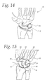
- FIG. 14 is a view as in FIG. 1 and showing zones where cartilage is removed from against carpal bones as part of the inventive method;
- FIG. 15 is a view as in FIG. 14 and showing the distal assembly operatively positioned
- FIG. 16 is a view as in FIG. 15 and showing the distal assembly and carpal bones moved to a different angle relative to the metacarpus region;
- FIG. 17 is a view as in FIG. 15 and showing locations for fasteners to secure the distal assembly
- FIG. 18 is a reduced view as in FIG. 17 and showing a specific form of proximal assembly with the patient's radius removed;
- FIG. 19 is a view as in FIG. 17 with the patient's hand turned to a different orientation relative to the proximal assembly.
- FIG. 2 is a schematic representation of a prosthesis at 22 , according to the present invention.
- the schematic showing of the prosthesis 22 is intended to encompass the specific forms hereinbelow described, as well as ones with variations of the basic components and their interaction as would be apparent to one skilled in the art based upon the teachings herein.
- the prosthesis 22 consists of a distal assembly 24 attached to a patient's hand 10 and a cooperating proximal assembly 26 attached to a patient's arm/radius 14 .
- the distal assembly 24 has a body 28 with at least one surface 30 that cooperates with at least one surface 32 on the proximal assembly 26 to controllably guide relative movement between the patient's hand 10 and radius 14 .
- FIG. 2 may take a form as shown herein or may be modified in virtually an unlimited number of ways to perform a method consistent with the teachings herein.
- a method of reconstructing a patient's wrist, to facilitate movement between the patient's hand 10 and radius 14 can be carried out as shown in flow diagram form in FIG. 3 .
- a prosthesis is provided as represented in FIG. 2 .
- the proximal assembly is fixed to the patient's radius.
- the patient's hand is prepared for placement of the distal assembly by removing cartilage against a plurality of carpal bones without significantly altering the configuration of the stable volume of at least one of the carpal bones in the patient's first carpal/proximal row—namely the scaphoid, lunate, and triquetrum bones 16 , 18 , 20 , successively.
- the cartilage of the pisiform carpal bone 39 is preferably left intact.
- the stable volume of at least one of the patient's scaphoid and lunate carpal bones is kept substantially intact.
- the stable volume of all the carpal bones in the first carpal row is retained intact.
- a U-shaped portion of the body on the distal assembly is placed against at least the scaphoid and lunate carpal bones and secured to a plurality of the patient's carpal bones.
- the cooperating surfaces on the proximal and distal assemblies guide multi-dimensional movement between the proximal and distal assemblies in a controlled manner intended to simulate natural wrist motion.
- the distal assembly 24 has at least a portion that is U-shaped.
- substantially the entire body 28 is U-shaped, consisting of an elongate base 42 having a length, as indicated by the double-headed arrow L, and extending into spaced legs 44 , 46 which project in substantially parallel lines.
- the body 28 has oppositely facing first and second U-shaped surfaces 48 , 30 , respectively.
- the first U-shaped surface 48 faces the patient's hand 10 with the body 28 secured to the patient's hand 10 .
- the first U-shaped surface 48 on the body 28 is secured against certain of the patient's carpal bones.
- the U-shaped surface 48 is configured to nominally match the contour of, and extend over, a plurality of carpal bones; namely the scaphoid carpal bone 16 , the lunate carpal bone 18 , and the triquetrum carpal bone 20 which together make up the first carpal row.
- cartilage against the carpal bones in the first carpal row in the zone Z, identified in FIG. 14 is removed, thereby to allow direct contact between the first U-shaped surface 48 on the body 28 and a plurality, or all, of the carpal bones in the first carpal row.
- the cartilage of the pisiform carpal bone 39 is preferably left intact so that there is no direct contact between the body 28 and pisiform carpal bone 39 .
- the configuration of the stable volumes of the carpal bones is not significantly altered during this process.
- the carpal bones in the first carpal row that are not compromised by arthritis, or injury, etc., remain significantly intact, whereby they might be utilized in a subsequent procedure to replace or reconstruct the distal assembly 24 on the prosthesis 22 .
- Additional cartilage on and between carpal bones is removed in the zone identified as Z 1 in FIG. 14 .
- direct bone-on-bone contact is permitted between: a) the triquetrum carpal bone 20 and hamate carpal bone 50 ; b) the lunate carpal bone 18 and capitate carpal bone 52 ; and c) the scaphoid carpal bone 16 and capitate carpal bone 52 .
- Additional cartilage may be removed from against carpal bones in the first carpal row, and those making up the distal carpal row—namely, the capitate and hamate carpal bones 52 , 50 , successively.
- the carpal bones are fused where there is direct bone-on-bone contact, preferably including an arthrodesis of the midcarpal joint between the first and second rows (capitate and hamate).
- This fusion may be effected separately as by the use of grafting material and/or additional structural components. More preferably, the fusion is effected through fasteners 60 extending in three separate lines L 1 , L 2 , L 3 , as identified in FIG. 17 , used to secure the body 28 .
- the fasteners 60 may take any conventional form and will typically be threaded fasteners with heads that seat in undercuts 62 so as not to project appreciably from the surface contour of the body 28 .
- a fastener 60 extending in the line L 1 is directed through the lunate carpal bone 18 and into the capitate carpal bone 52 .
- the fastener 60 extending along the line L 2 extends through the hamate carpal bone 50 and into the capitate carpal bone 52 .
- the fastener 60 extending in the line L 3 extends through the scaphoid carpal bone 16 and into the capitate carpal bone 52 .
- the carpal bone fusion is facilitated. Further, the bone-on-bone contact affords greater stability. Still further, the removed cartilage creates a space approximately equaling that required for the body 28 so that the total dimension of the hand and wrist, including the body 28 , between the fingertips and radius 14 is not substantially changed.
- the second U-shaped surface 30 is configured to cooperate with the surface 32 on the proximal assembly 26 in a manner as described in detail below.
- the “U” of the second surface 30 opens in the same direction, i.e., towards the patient's hand 10 , as the first U-shaped surface 48 .
- the proximal assembly 26 is attached to the radius 14 using any conventional structure and technique.
- the proximal assembly 26 is shown connected to the radius 14 using one or more fixation parts 66 that are shown schematically in that Figure.
- One specific form of the fixation part(s) 66 is shown in FIG. 18 .
- a solid foundation is provided for the body 28 .
- the body 28 contacts and is stabilized by at least two of the carpal bones in the first carpal row.
- all bones in the first carpal row remain intact as part of the unified mass that supports the body 28 .
- the fastener 60 extending in the line L 2 is advanced in a first direction through the body 28 in the line L 2 that is transverse to a reference line RL that extends generally parallel to the length of the patient's radius 14 .
- a separate fastener 60 extending along the line L 3 is advanced in a direction generally oppositely to the first direction for introduction of the fastener 60 in the line L 2 .
- the line L 3 is transverse to the reference line RL.
- the fasteners 60 inserted in this manner are generally perpendicular to the direction of forces of distraction in the carpal region. This tends to avoid and provide resistance to distraction forces and to fractures and loosening of the fasteners 60 in the carpal region.
- the surfaces 30 , 32 are configured to guide relative movement between the body 28 and proximal assembly 26 in multiple dimensions. As seen in FIG. 6 , the U-shaped surfaces 30 , 32 are approximated by arcs of circles with radii R 1 , R 2 , respectively.
- the radius R 1 is centered on a line C 1 , with the radius R 2 centered on a parallel line C 2 .
- the lines C 1 , C 2 are substantially perpendicular to a plane bisecting the patient's fingers in a flattened state with the finger lengths aligned with the length of the radius 14 .
- the radius R 1 is less than the radius R 2 , as a result of which the surfaces 30 , 32 are not in contact over their full angular coincidence.
- the body 28 is guided by the surface 32 in an arcuate path, indicated by the double-headed arrow 68 , without any substantial resistance or likelihood of binding over the angular length AL ( FIG. 16 ) of the surface 32 that contacts the surface 30 as the hand 10 articulates relative to the radius 14 .
- the surfaces 30 , 32 also have cooperating convex/concave shapes as viewed from a perspective taken transversely to the length L of the elongate base 42 on the body 28 .
- This construction likewise facilitates the aforementioned guided movement of the body 28 relative to the proximal assembly 26 without significant impedance, while at the same time controlling skewing between the body 28 and proximal assembly 26 .
- FIGS. 7-13 show a series of cross-sectional views from the indicated perspective over the angular range where the surfaces 30 , 32 co-act.
- the surface 32 is approximated by an arc of a circle with a radius R 4 .
- the surface 30 is approximated by the arc of a circle with a radius R 3 .
- the radii R 3 , R 4 are centered on spaced, parallel lines C 3 , C 4 , respectively.
- the radius R 3 is less than the radius R 4 . Accordingly, there is not a conforming contact region over the full width W where the surfaces 30 , 32 coincide. This has two significant advantages.
- the non-conforming contact affords the necessary controlled guidance between the body 28 and proximal assembly 26 in the path indicated by the double-headed arrow 68 , but does not cause any significant binding between these components.
- the described configuration produces gaps G 1 , G 2 between the surfaces 30 , 32 at the widthwise ends of the overlapping regions of the surfaces 30 , 32 region.
- the body 28 is allowed to turn relative to the proximal assembly 26 in a controlled range around a line 70 ( FIG. 6 ) that extends generally parallel to the length of the patient's radius 14 , as indicated by the double-headed arrow 71 ( FIGS. 4 and 19 ).
- the radii R 1 , R 2 , R 3 , R 4 can be selected to control the range of turning around the line 70 , which is preferably at least 10° total, and more preferably 10° ⁇ from center.
- the surfaces 30 , 32 interfere with each other at spaced widthwise locations to block further turning.
- the body has three different openings 72 , 74 , 76 formed therethrough at spaced locations to accept fasteners 60 .
- Each opening 72 , 74 , 76 is countersunk, as previously described, to allow a head on the fasteners 60 to seat flushly with the surface 30 so as to not create a localized friction point.
- the opening 74 is offset closer to the leg 46 so that the fastener 60 therein is not likely to contact the surface 32 as the body 28 moves in its intended range.
- the above prosthesis 22 can be inserted in post-traumatic patients and patients with osteoarthritis or chondrocalcinosis of the wrist.
Landscapes
- Health & Medical Sciences (AREA)
- Orthopedic Medicine & Surgery (AREA)
- Cardiology (AREA)
- Oral & Maxillofacial Surgery (AREA)
- Transplantation (AREA)
- Engineering & Computer Science (AREA)
- Biomedical Technology (AREA)
- Heart & Thoracic Surgery (AREA)
- Vascular Medicine (AREA)
- Life Sciences & Earth Sciences (AREA)
- Animal Behavior & Ethology (AREA)
- General Health & Medical Sciences (AREA)
- Public Health (AREA)
- Veterinary Medicine (AREA)
- Prostheses (AREA)
Abstract
Description
Claims (24)
Priority Applications (2)
| Application Number | Priority Date | Filing Date | Title |
|---|---|---|---|
| US14/289,140 US9468533B2 (en) | 2013-05-30 | 2014-05-28 | Method of reconstructing a patient's wrist |
| FR1454917A FR3006171A1 (en) | 2013-05-30 | 2014-05-30 | PROCESS FOR RESTORING A PATIENT'S WRIST |
Applications Claiming Priority (2)
| Application Number | Priority Date | Filing Date | Title |
|---|---|---|---|
| US201361828933P | 2013-05-30 | 2013-05-30 | |
| US14/289,140 US9468533B2 (en) | 2013-05-30 | 2014-05-28 | Method of reconstructing a patient's wrist |
Publications (2)
| Publication Number | Publication Date |
|---|---|
| US20140358243A1 US20140358243A1 (en) | 2014-12-04 |
| US9468533B2 true US9468533B2 (en) | 2016-10-18 |
Family
ID=51985984
Family Applications (1)
| Application Number | Title | Priority Date | Filing Date |
|---|---|---|---|
| US14/289,140 Active US9468533B2 (en) | 2013-05-30 | 2014-05-28 | Method of reconstructing a patient's wrist |
Country Status (2)
| Country | Link |
|---|---|
| US (1) | US9468533B2 (en) |
| FR (1) | FR3006171A1 (en) |
Families Citing this family (3)
| Publication number | Priority date | Publication date | Assignee | Title |
|---|---|---|---|---|
| CA3017712C (en) * | 2016-03-28 | 2020-10-27 | Wright Medical Technology, Inc. | Anterior resurfacing talar plate |
| US11166822B2 (en) * | 2017-09-08 | 2021-11-09 | Orthopedix, Inc. | Implant for total wrist replacement |
| CN111134909B (en) * | 2018-11-06 | 2022-04-12 | 贵州澳特拉斯科技有限公司 | Combined semi-limited multi-polar artificial wrist joint |
Citations (4)
| Publication number | Priority date | Publication date | Assignee | Title |
|---|---|---|---|---|
| US5702470A (en) * | 1996-02-23 | 1997-12-30 | Kinetikos Medical Incorporated | Prosthetic wrist implant and related method of implantation |
| US6383223B1 (en) * | 1997-06-18 | 2002-05-07 | BAEHLER ANDRé | Endoprosthesis for a joint, especially a finger, toe or wrist joint |
| US20070185582A1 (en) * | 2006-01-24 | 2007-08-09 | Palmer Andrew K | Methods and Devices for Resurfacing the Wrist Joint |
| US20100010636A1 (en) * | 2002-10-24 | 2010-01-14 | Biomet Manufacturing Corp. | Method and Apparatus for Wrist Arthroplasty |
-
2014
- 2014-05-28 US US14/289,140 patent/US9468533B2/en active Active
- 2014-05-30 FR FR1454917A patent/FR3006171A1/en not_active Withdrawn
Patent Citations (4)
| Publication number | Priority date | Publication date | Assignee | Title |
|---|---|---|---|---|
| US5702470A (en) * | 1996-02-23 | 1997-12-30 | Kinetikos Medical Incorporated | Prosthetic wrist implant and related method of implantation |
| US6383223B1 (en) * | 1997-06-18 | 2002-05-07 | BAEHLER ANDRé | Endoprosthesis for a joint, especially a finger, toe or wrist joint |
| US20100010636A1 (en) * | 2002-10-24 | 2010-01-14 | Biomet Manufacturing Corp. | Method and Apparatus for Wrist Arthroplasty |
| US20070185582A1 (en) * | 2006-01-24 | 2007-08-09 | Palmer Andrew K | Methods and Devices for Resurfacing the Wrist Joint |
Also Published As
| Publication number | Publication date |
|---|---|
| US20140358243A1 (en) | 2014-12-04 |
| FR3006171A1 (en) | 2014-12-05 |
Similar Documents
| Publication | Publication Date | Title |
|---|---|---|
| US20230101398A1 (en) | Method and apparatus for joint replacement arthroplasty | |
| US4259752A (en) | Endoprosthetic wrist joint | |
| US5314485A (en) | Total prosthesis of the wrist | |
| US5507821A (en) | Artificial wrist joint | |
| US4936860A (en) | Metal scaphoid implant | |
| US10918493B2 (en) | Joint replacement device | |
| US5702470A (en) | Prosthetic wrist implant and related method of implantation | |
| US9173691B2 (en) | Devices, implements and methods for the treatment of a multi-axis joint | |
| JP5390192B2 (en) | Humeral component | |
| US20180221161A1 (en) | A joint prosthesis | |
| US20080221698A1 (en) | Semi-Constrained 1st Carpometacarpal Implant Arthroplasty | |
| US9468533B2 (en) | Method of reconstructing a patient's wrist | |
| Pulos et al. | Carpal ligament anatomy and biomechanics | |
| Orbay et al. | Locked intramedullary total wrist arthrodesis | |
| US10182915B2 (en) | Cartilage prosthetic implant | |
| US10925746B2 (en) | Patient specific carpal implant | |
| US20190201207A1 (en) | Proximal carpal row implant | |
| US10918487B2 (en) | Prosthetic implant caps | |
| RU2770988C1 (en) | Implant for replacement of the distal radius | |
| Manske | Instructional course lectures, the American Academy of Orthopaedic Surgeons-longitudinal failure of upper-limb formation | |
| JP7402809B2 (en) | Method using wrist joint fixation plate and wrist joint fixation plate | |
| RU223394U1 (en) | Wrist joint endoprosthesis | |
| US20110118849A1 (en) | Modular Hip Joint Prosthesis and Assembling Method Thereof | |
| US12329650B2 (en) | Artificial joint | |
| RU2726597C1 (en) | Method for replacement of navicular bone of hand defects in experiment |
Legal Events
| Date | Code | Title | Description |
|---|---|---|---|
| STCF | Information on status: patent grant |
Free format text: PATENTED CASE |
|
| MAFP | Maintenance fee payment |
Free format text: PAYMENT OF MAINTENANCE FEE, 4TH YR, SMALL ENTITY (ORIGINAL EVENT CODE: M2551); ENTITY STATUS OF PATENT OWNER: SMALL ENTITY Year of fee payment: 4 |
|
| AS | Assignment |
Owner name: TRIMED, INC., CALIFORNIA Free format text: ASSIGNMENT OF ASSIGNORS INTEREST;ASSIGNORS:SAFFAR, PHILIPPE;HAKANSSON, ANDERS;SIGNING DATES FROM 20130629 TO 20130722;REEL/FRAME:066189/0899 |
|
| AS | Assignment |
Owner name: TRIMED INC., CALIFORNIA Free format text: CORRECTIVE ASSIGNMENT TO CORRECT THE RECEIVING PARTY NAME INSIDE THE DOCUMENT PREVIOUSLY RECORDED AT REEL: 66189 FRAME: 899. ASSIGNOR(S) HEREBY CONFIRMS THE ASSIGNMENT;ASSIGNORS:SAFFAR, PHILIPPE;HAKANSSON, ANDERS;SIGNING DATES FROM 20130629 TO 20130722;REEL/FRAME:066544/0769 |
|
| MAFP | Maintenance fee payment |
Free format text: PAYMENT OF MAINTENANCE FEE, 8TH YR, SMALL ENTITY (ORIGINAL EVENT CODE: M2552); ENTITY STATUS OF PATENT OWNER: SMALL ENTITY Year of fee payment: 8 |
|
| AS | Assignment |
Owner name: TRIMED, INC., CALIFORNIA Free format text: CHANGE OF NAME;ASSIGNOR:TRIMED INC.;REEL/FRAME:068916/0799 Effective date: 20240816 |