US9464674B2 - Fixed type constant velocity universal joint - Google Patents
Fixed type constant velocity universal joint Download PDFInfo
- Publication number
- US9464674B2 US9464674B2 US14/362,659 US201214362659A US9464674B2 US 9464674 B2 US9464674 B2 US 9464674B2 US 201214362659 A US201214362659 A US 201214362659A US 9464674 B2 US9464674 B2 US 9464674B2
- Authority
- US
- United States
- Prior art keywords
- joint member
- center
- track grooves
- track groove
- track
- Prior art date
- Legal status (The legal status is an assumption and is not a legal conclusion. Google has not performed a legal analysis and makes no representation as to the accuracy of the status listed.)
- Active
Links
- 230000002093 peripheral effect Effects 0.000 claims abstract description 116
- 230000020169 heat generation Effects 0.000 description 15
- 238000012986 modification Methods 0.000 description 10
- 230000004048 modification Effects 0.000 description 10
- 238000000034 method Methods 0.000 description 4
- 238000011161 development Methods 0.000 description 3
- 238000006073 displacement reaction Methods 0.000 description 3
- 101100203596 Caenorhabditis elegans sol-1 gene Proteins 0.000 description 2
- 238000013461 design Methods 0.000 description 2
- 239000004519 grease Substances 0.000 description 2
- 238000011835 investigation Methods 0.000 description 2
- 239000000314 lubricant Substances 0.000 description 2
- 230000001629 suppression Effects 0.000 description 2
- 244000141359 Malus pumila Species 0.000 description 1
- 235000021016 apples Nutrition 0.000 description 1
- 230000005540 biological transmission Effects 0.000 description 1
- 230000007423 decrease Effects 0.000 description 1
- 230000000694 effects Effects 0.000 description 1
- 230000001788 irregular Effects 0.000 description 1
- 238000012795 verification Methods 0.000 description 1
Images


Classifications
-
- F—MECHANICAL ENGINEERING; LIGHTING; HEATING; WEAPONS; BLASTING
- F16—ENGINEERING ELEMENTS AND UNITS; GENERAL MEASURES FOR PRODUCING AND MAINTAINING EFFECTIVE FUNCTIONING OF MACHINES OR INSTALLATIONS; THERMAL INSULATION IN GENERAL
- F16D—COUPLINGS FOR TRANSMITTING ROTATION; CLUTCHES; BRAKES
- F16D3/00—Yielding couplings, i.e. with means permitting movement between the connected parts during the drive
- F16D3/16—Universal joints in which flexibility is produced by means of pivots or sliding or rolling connecting parts
- F16D3/24—Universal joints in which flexibility is produced by means of pivots or sliding or rolling connecting parts comprising balls, rollers, or the like between overlapping driving faces, e.g. cogs, on both coupling parts
-
- F—MECHANICAL ENGINEERING; LIGHTING; HEATING; WEAPONS; BLASTING
- F16—ENGINEERING ELEMENTS AND UNITS; GENERAL MEASURES FOR PRODUCING AND MAINTAINING EFFECTIVE FUNCTIONING OF MACHINES OR INSTALLATIONS; THERMAL INSULATION IN GENERAL
- F16D—COUPLINGS FOR TRANSMITTING ROTATION; CLUTCHES; BRAKES
- F16D3/00—Yielding couplings, i.e. with means permitting movement between the connected parts during the drive
- F16D3/16—Universal joints in which flexibility is produced by means of pivots or sliding or rolling connecting parts
- F16D3/20—Universal joints in which flexibility is produced by means of pivots or sliding or rolling connecting parts one coupling part entering a sleeve of the other coupling part and connected thereto by sliding or rolling members
- F16D3/22—Universal joints in which flexibility is produced by means of pivots or sliding or rolling connecting parts one coupling part entering a sleeve of the other coupling part and connected thereto by sliding or rolling members the rolling members being balls, rollers, or the like, guided in grooves or sockets in both coupling parts
- F16D3/223—Universal joints in which flexibility is produced by means of pivots or sliding or rolling connecting parts one coupling part entering a sleeve of the other coupling part and connected thereto by sliding or rolling members the rolling members being balls, rollers, or the like, guided in grooves or sockets in both coupling parts the rolling members being guided in grooves in both coupling parts
- F16D3/2233—Universal joints in which flexibility is produced by means of pivots or sliding or rolling connecting parts one coupling part entering a sleeve of the other coupling part and connected thereto by sliding or rolling members the rolling members being balls, rollers, or the like, guided in grooves or sockets in both coupling parts the rolling members being guided in grooves in both coupling parts where the track is made up of two curves with a point of inflexion in between, i.e. S-track joints
-
- F—MECHANICAL ENGINEERING; LIGHTING; HEATING; WEAPONS; BLASTING
- F16—ENGINEERING ELEMENTS AND UNITS; GENERAL MEASURES FOR PRODUCING AND MAINTAINING EFFECTIVE FUNCTIONING OF MACHINES OR INSTALLATIONS; THERMAL INSULATION IN GENERAL
- F16D—COUPLINGS FOR TRANSMITTING ROTATION; CLUTCHES; BRAKES
- F16D3/00—Yielding couplings, i.e. with means permitting movement between the connected parts during the drive
- F16D3/16—Universal joints in which flexibility is produced by means of pivots or sliding or rolling connecting parts
- F16D3/20—Universal joints in which flexibility is produced by means of pivots or sliding or rolling connecting parts one coupling part entering a sleeve of the other coupling part and connected thereto by sliding or rolling members
- F16D3/22—Universal joints in which flexibility is produced by means of pivots or sliding or rolling connecting parts one coupling part entering a sleeve of the other coupling part and connected thereto by sliding or rolling members the rolling members being balls, rollers, or the like, guided in grooves or sockets in both coupling parts
- F16D3/223—Universal joints in which flexibility is produced by means of pivots or sliding or rolling connecting parts one coupling part entering a sleeve of the other coupling part and connected thereto by sliding or rolling members the rolling members being balls, rollers, or the like, guided in grooves or sockets in both coupling parts the rolling members being guided in grooves in both coupling parts
- F16D3/224—Universal joints in which flexibility is produced by means of pivots or sliding or rolling connecting parts one coupling part entering a sleeve of the other coupling part and connected thereto by sliding or rolling members the rolling members being balls, rollers, or the like, guided in grooves or sockets in both coupling parts the rolling members being guided in grooves in both coupling parts the groove centre-lines in each coupling part lying on a sphere
-
- F—MECHANICAL ENGINEERING; LIGHTING; HEATING; WEAPONS; BLASTING
- F16—ENGINEERING ELEMENTS AND UNITS; GENERAL MEASURES FOR PRODUCING AND MAINTAINING EFFECTIVE FUNCTIONING OF MACHINES OR INSTALLATIONS; THERMAL INSULATION IN GENERAL
- F16D—COUPLINGS FOR TRANSMITTING ROTATION; CLUTCHES; BRAKES
- F16D3/00—Yielding couplings, i.e. with means permitting movement between the connected parts during the drive
- F16D3/16—Universal joints in which flexibility is produced by means of pivots or sliding or rolling connecting parts
- F16D3/20—Universal joints in which flexibility is produced by means of pivots or sliding or rolling connecting parts one coupling part entering a sleeve of the other coupling part and connected thereto by sliding or rolling members
- F16D3/22—Universal joints in which flexibility is produced by means of pivots or sliding or rolling connecting parts one coupling part entering a sleeve of the other coupling part and connected thereto by sliding or rolling members the rolling members being balls, rollers, or the like, guided in grooves or sockets in both coupling parts
- F16D3/223—Universal joints in which flexibility is produced by means of pivots or sliding or rolling connecting parts one coupling part entering a sleeve of the other coupling part and connected thereto by sliding or rolling members the rolling members being balls, rollers, or the like, guided in grooves or sockets in both coupling parts the rolling members being guided in grooves in both coupling parts
- F16D2003/22306—Universal joints in which flexibility is produced by means of pivots or sliding or rolling connecting parts one coupling part entering a sleeve of the other coupling part and connected thereto by sliding or rolling members the rolling members being balls, rollers, or the like, guided in grooves or sockets in both coupling parts the rolling members being guided in grooves in both coupling parts having counter tracks, i.e. ball track surfaces which diverge in opposite directions
-
- Y—GENERAL TAGGING OF NEW TECHNOLOGICAL DEVELOPMENTS; GENERAL TAGGING OF CROSS-SECTIONAL TECHNOLOGIES SPANNING OVER SEVERAL SECTIONS OF THE IPC; TECHNICAL SUBJECTS COVERED BY FORMER USPC CROSS-REFERENCE ART COLLECTIONS [XRACs] AND DIGESTS
- Y10—TECHNICAL SUBJECTS COVERED BY FORMER USPC
- Y10S—TECHNICAL SUBJECTS COVERED BY FORMER USPC CROSS-REFERENCE ART COLLECTIONS [XRACs] AND DIGESTS
- Y10S464/00—Rotary shafts, gudgeons, housings, and flexible couplings for rotary shafts
- Y10S464/904—Homokinetic coupling
- Y10S464/906—Torque transmitted via radially spaced balls
Definitions
- the present invention relates to a fixed type constant velocity universal joint, and more specifically, to a fixed type constant velocity universal joint to be used in a power transmission system of automobiles and various industrial machines, for allowing only angular displacement between two shafts on a driving side and a driven side.
- a plunging type constant velocity universal joint capable of allowing axial displacement while forming an operating angle including a relatively low maximum operating angle is generally assembled on an inboard side (differential side) of an automotive front drive shaft.
- a fixed type constant velocity universal joint capable of forming high operating angles while avoiding axial displacement is assembled in consideration of steering of the wheel.
- FIG. 25 illustrate a Rzeppa type constant velocity universal joint 101 as an example of the fixed type constant velocity universal joint to be used on the outboard side.
- FIG. 25 a is a vertical sectional view of a state in which an operating angle is 0°
- FIG. 25 b is a schematic view of a state in which a maximum operating angle is formed.
- the constant velocity universal joint 101 mainly includes an outer joint member 102 , an inner joint member 103 , balls 104 , and a cage 105 .
- Eight track grooves 107 are formed equiangularly in a spherical inner peripheral surface 106 of the outer joint member 102 so as to extend along an axial direction.
- Track grooves 109 opposed to the track grooves 107 of the outer joint member 102 are formed equiangularly in a spherical outer peripheral surface 108 of the inner joint member 103 so as to extend along the axial direction.
- the eight balls 104 for transmitting torque are interposed between the track grooves 107 of the outer joint member 102 and the track grooves 109 of the inner joint member 103 , respectively.
- the cage 105 for holding the balls 104 is arranged between the spherical inner peripheral surface 106 of the outer joint member 102 and the spherical outer peripheral surface 108 of the inner joint member 103 .
- An outer periphery of the outer joint member 102 and an outer periphery of a shaft coupled to the inner joint member 103 are covered with a boot, and grease is sealed inside the joint as a lubricant (not shown).
- the cage 105 has a spherical outer peripheral surface 112 fitted to the spherical inner peripheral surface 106 of the outer joint member 102 , and a spherical inner peripheral surface 113 fitted to the spherical outer peripheral surface 108 of the inner joint member 103 .
- the spherical outer peripheral surface 112 and the spherical inner peripheral surface 113 each have a curvature center formed at a joint center O.
- a curvature center Oo of a ball raceway center line x of each track groove 107 of the outer joint member 102 and a curvature center Oi of a ball raceway center line y of each track groove 109 of the inner joint member 103 are offset in the axial direction by equal distances with respect to the joint center O. Therefore, when the joint forms an operating angle, the balls 104 are always guided in a plane bisecting an angle formed between axial lines of the outer joint member 102 and the inner joint member 103 . As a result, rotational torque is transmitted at a constant velocity between the two axes.
- a maximum operating angle ⁇ max which is defined as a main function of the fixed type constant velocity universal joint 101 , depends on an angle causing interference between an inlet chamfer 110 provided at an opening rim of the outer joint member 102 and a shaft 111 .
- an axial diameter d of the shaft 111 is determined for each joint size.
- the ball 104 may drop off the track groove 107 , and the rotational torque cannot be transmitted. Therefore, how the inlet chamfer 110 is formed while securing the effective track length of the outer joint member 102 is an important factor in securing the operating angle.
- the curvature center Oo of the ball raceway center line x of the track groove 107 of the outer joint member 102 is offset to an opening side, and hence there is an advantage in terms of the maximum operating angle.
- the maximum operating angle ⁇ max is approximately 47°.
- the Rzeppa type constant velocity universal joint 101 of an eight-ball type has a smaller track offset amount, a larger number of balls, and has a smaller diameter.
- wedge angles formed between the opposing track grooves 107 and 109 of the outer joint member 102 and the inner joint member 103 are opened toward the opening side of the outer joint member 102 .
- FIGS. 26 and 27 illustrate this constant velocity universal joint.
- FIG. 26 is a vertical sectional view of a state in which the operating angle is 0°
- FIG. 27 are views of a state in which a high operating angle is formed.
- a constant velocity universal joint 121 mainly includes an outer joint member 122 , an inner joint member 123 , balls 124 , and a cage 125 .
- the constant velocity universal joint 121 is a constant velocity universal joint of the track groove crossing type.
- each track groove 129 of the inner joint member 123 has a ball raceway center line y, which is formed so as to be mirror-image symmetrical with the ball raceway center line x of the paired track groove 127 of the outer joint member 122 with respect to a plane P including a joint center O at the operating angle of 0°.
- the track groove 127 formed in a spherical inner peripheral surface 126 of the outer joint member 122 extends into an arc shape along the axial direction, and a curvature center of the track groove 127 is positioned at the joint center O.
- the track groove 129 opposed to the track groove 127 of the outer joint member 122 extends into an arc shape along the axial direction, and a curvature center of the track groove 129 is positioned at the joint center O.
- the eight balls 124 for transmitting torque are interposed in crossing portions between the track grooves 127 of the outer joint member 122 and the track grooves 129 of the inner joint member 123 .
- the cage 125 for holding the balls 124 is arranged between the spherical inner peripheral surface 126 of the outer joint member 122 and the spherical outer peripheral surface 128 of the inner joint member 123 .
- the cage 125 has a spherical outer peripheral surface 132 fitted to the spherical inner peripheral surface 126 of the outer joint member 122 , and a spherical inner peripheral surface 133 fitted to the spherical outer peripheral surface 128 of the inner joint member 123 .
- the spherical outer peripheral surface 132 and the spherical inner peripheral surface 133 each have a curvature center formed at the joint center O.
- curvature centers of the ball raceway center lines x and y of the respective track grooves 127 and 129 of the outer joint member 122 and the inner joint member 123 are not offset in the axial direction with respect to the joint center O.
- the track grooves 127 and 129 thus inclined and opposed cross each other, and the balls 124 are interposed in those crossing portions. Therefore, when the joint forms an operating angle, the balls 124 are always guided in a plane bisecting an angle formed between axial lines of the outer joint member 122 and the inner joint member 123 . As a result, rotational torque is transmitted at a constant velocity between the two axes.
- the track grooves 127 of the outer joint member 122 that are adjacent to each other in the peripheral direction are inclined in the opposite directions.
- the track grooves 129 of the inner joint member 123 that are adjacent to each other in the peripheral direction are inclined in the opposite directions. Therefore, forces in the opposite directions are applied from the balls 124 to pocket portions 125 a of the cage 125 that are adjacent to each other in the peripheral direction. Due to the forces in the opposite directions, the cage 125 is stabilized at the position of the joint center O.
- FIG. 27 a illustrates a state in which the above-mentioned constant velocity universal joint forms a high operating angle
- FIG. 27 b illustrates a positional relationship between the track groove 127 of the outer joint member 122 and the ball 124 on an enlarged scale.
- the ball 124 and the track groove 127 are held in angular contact with each other at a contact angle, and hence a contact point between the ball 124 and the track groove 127 is positioned on the broken line of FIG. 27 b .
- the contact point between the ball 124 and the track groove 127 is positioned in a plane t that passes through the center Ob of the ball 124 and is orthogonal to the ball raceway center line x.
- FIG. 23 illustrate this constant velocity universal joint.
- FIG. 23 a illustrates a vertical cross section
- FIG. 23 b illustrates a right side of FIG. 23 a .
- a constant velocity universal joint 141 includes an outer joint member 142 and an inner joint member 143 respectively having track grooves 147 and 149 of a crossing type.
- the track grooves 147 of the outer joint member 142 each include a track groove portion 147 a provided on an interior side with respect to the joint center O and having an arc-shaped ball raceway center line xa that has a curvature center at the joint center O, and a track groove portion 147 b provided on the opening side with respect to the joint center O and having a straight ball raceway center line xb.
- the track grooves 149 of the inner joint member 143 each include a track groove portion 149 b provided on the interior side with respect to the joint center O and having a straight ball raceway center line yb, and a track groove portion 149 a provided on the opening side with respect to the joint center O and having an arc-shaped ball raceway center line ya that has a curvature center at the joint center O.
- the track grooves 147 include track grooves 147 A and 147 B that are inclined in a peripheral direction with respect to a joint axial line and adjacent to each other in the peripheral direction with their inclination directions opposite to each other.
- the track grooves 149 include track grooves 149 A and 149 B that are inclined in the peripheral direction with respect to the joint axial line and adjacent to each other in the peripheral direction with their inclination directions opposite to each other.
- balls 144 are arranged in crossing portions of the paired track grooves 147 A and 149 A and the paired track grooves 147 B and 149 B of the outer joint member 142 and the inner joint member 143 .
- the track grooves 147 and 149 are held in contact with the ball 144 at positions indicated by the broken lines on side surface sides of the track grooves 147 and 149 , which are slightly spaced apart from groove bottoms of the track grooves 147 and 149 .
- wedge angle components (not shown) due to the crossing between the track grooves 147 and 149 and wedge angle components ⁇ due to expansion between the groove bottoms of the track grooves 147 and 149 in a radial direction of the joint are both applied to the balls 144 .
- the wedge angle components due to the crossing between the track grooves 147 and 149 are canceled and forces are balanced because the track grooves 147 and 149 are inclined in the directions opposite to each other and hence forces in the opposite directions are applied from the balls 144 to the pocket portions 145 a of the cage 145 .
- the balls 144 within phase ranges of from 0° to 90° and from 270° to 360° in FIG. 23 b are positioned between the straight track groove portions 147 b and 149 b . Due to a wedge angle component ⁇ 1 opened toward the opening side, a force toward the opening side is applied to the balls 144 within those phase ranges. On the other hand, the balls 144 within a phase range of from 90° to 270° are positioned between the arc-shaped track groove portions 147 a and 149 a .
- a wedge angle component ⁇ 2 which is generated due to the expansion in the radial direction of the joint, is zero in the balls within this phase range, and hence no push-out force is generated in the balls 144 .
- the wedge angle components due to the crossing between the track grooves 147 and 149 and the wedge angle components ⁇ due to the expansion between the groove bottoms of the track grooves 147 and 149 in the radial direction of the joint are applied to the balls 144 in combination, the forces applied from the balls 144 to the pocket portions 145 a of the cage 145 are not balanced with each other.
- the straight track groove portion 147 b is formed parallel to a joint axial line that corresponds to projection of the joint axial line n-n onto a plane including the ball raceway center line x and the joint center O.
- the straight track groove portion 149 b is formed parallel to the joint axial line that corresponds to projection of the joint axial line n-n onto a plane including the ball raceway center line y and the joint center O.
- the present invention has an object to provide a compact fixed type constant velocity universal joint that is suppressed in torque loss and heat generation, enhanced in efficiency, capable of forming high operating angles, and is excellent in strength and durability at the high operating angles.
- track grooves are formed so as to cross each other in a peripheral direction.
- a first track groove portion having an arc-shaped ball raceway line that has a curvature center prevented from being offset in the axial direction with respect to a joint center is provided so as to be adaptable to a range of frequently used operating angles
- an arc-shaped second track groove portion that is curved in an opposite direction to that of the first track groove portion so as to increase an effective track length with respect to a maximum operating angle is provided so as to be adaptable to a range of less frequently used high operating angles.
- the inventors of the present invention have found a novel standard for suppressing a degree of a wedge angle between the second track groove portions at high operating angles.
- a fixed type constant velocity universal joint comprising: an outer joint member having a spherical inner peripheral surface in which a plurality of track grooves are formed so as to extend in an axial direction of the outer joint member, the outer joint member having an opening side and an interior side spaced apart from each other in the axial direction; an inner joint member having a spherical outer peripheral surface in which a plurality of track grooves are formed so as to be paired with the plurality of track grooves of the outer joint member; a plurality of balls for transmitting torque, the plurality of balls being interposed between the plurality of track grooves of the outer joint member and the plurality of track grooves of the inner joint member; and a cage comprising pockets for holding the plurality of balls, the cage having a spherical outer peripheral surface, which is fitted to the spherical inner peripheral surface of the outer joint member, and a spherical
- joint axial line herein refers to a longitudinal axial line that is a joint rotation center, and corresponds to a joint axial line N-N in the embodiments described later. The same applies to a joint axial line described in the claims.
- the end portion A of the arc-shaped ball raceway center line Xa of the each of the first track groove portions 7 a is positioned on the opening side with respect to the joint center O, the position of the end portion A occupies at least 60% of the effective track length on the opening side with respect to the joint center O, and the arc-shaped ball raceway center line Xb of each of the second track groove portions 7 b is connected to the end portion A.
- a degree of a wedge angle between each of the second track groove portions 7 b and corresponding one of the second track groove portions 9 b at high operating angles can be suppressed.
- a strength of the cage can be secured.
- an angle formed by a straight line L connecting the joint center O and the end portion A on the opening side of the arc-shaped ball raceway center line Xa of the each of the above-mentioned first track groove portions 7 a with respect to the plane P comprising the joint center O at the operating angle of 0° is represented by ⁇ , and it is preferred that the angle ⁇ be set to 14° to 16°.
- the angle ⁇ be set to approximately 10°.
- the range of the angle ⁇ of from 14° to 16° has been found as a novel standard for suppressing the degree of the wedge angle between the each of the second track groove portions 7 b and the corresponding one of the second track groove portions 9 b .
- the angle ⁇ is herein defined as the smallest angle among the angles formed by the straight line L with respect to the straight line on the plane P, and the same applies to the embodiments and the claims.
- the angle ⁇ be as high as possible.
- the angle ⁇ is excessively high, the effective track length decreases. In other words, an advantage obtained by providing the second track groove portions 7 b and the second track groove portions 9 b becomes insignificant, and hence the high operating angles cannot be formed.
- a required maximum operating angle of the fixed type constant velocity universal joints normally ranges from 46° to 50°, and it has been found that, in order to secure an effective track length that is required to form the operating angle of from 46° to 50°, the angle ⁇ is required to fall within the range of from 14° to 16° even when the effective track length that varies depending on a balance of a ball diameter and a PCD diameter is taken into consideration.
- a maximum value of the angle ⁇ is required to fall within the range of from 14° to 16°.
- parameters of the plurality of track grooves of the outer joint member and the plurality of track grooves of the inner joint member can be determined based on the wedge angle 2 ⁇ ′ in two-dimensional cross section at the phase angle ⁇ of 0°.
- work of setting the parameters of the plurality of track grooves of the outer joint member and the plurality of track grooves of the inner joint member can be markedly simplified. Further, such setting of the parameters enables strength and durability at the maximum operating angle to be secured equivalently to those of widely available related-art constant velocity universal joints.
- an allowance amount a be secured between the spherical outer peripheral surface of the cage and a contact point between the one of the plurality of balls and corresponding one of the pockets of the cage, the one of the plurality of balls being moved to an end of the radially outer side with respect to the corresponding one of the pockets.
- the curvature center of the arc-shaped ball raceway center line Xa of the each of the above-mentioned first track groove portions 7 a is arranged on the joint axial line N-N. With this, track groove depths can be equalized. Further, the curvature center of the arc-shaped ball raceway center line Xa of the each of the first track groove portions 7 a is offset in the radial direction with respect to the joint axial line N-N. With this, the track groove depths can be adjusted on the interior side of the joint, and hence an optimum track groove depth can be secured.
- the spherical outer peripheral surface of the cage and the spherical inner peripheral surface of the cage each have a curvature center that is offset in the axial direction with respect to the joint center O. With this, the thickness of the cage can be increased toward the opening side. As a result, a higher strength of the cage at the high operating angles can be secured.
- the number of the plurality of balls for transmitting torque is set to eight. With this, it is possible to attain a fixed type constant velocity universal joint and therefore an automotive drive shaft that are lightweight and compact, enhanced in efficiency, and are capable of forming high operating angles.
- the present invention it is possible to attain a compact fixed type constant velocity universal joint that is suppressed in torque loss and heat generation, enhanced in efficiency, capable of forming high operating angles, and is excellent in strength and durability at the high operating angles.
- the degrees of the wedge angles between the plurality of track grooves of the outer joint member and the plurality of track grooves of the inner joint member at the high operating angles can be suppressed.
- the strength of the cage can be secured.
- FIG. 1 a is a partial vertical sectional view of a fixed type constant velocity universal joint according to a first embodiment of the present invention.
- FIG. 1 b is a side view of the fixed type constant velocity universal joint.
- FIG. 2 a is a partial vertical sectional view of an outer joint member of the fixed type constant velocity universal joint.
- FIG. 2 b is a side view of the outer joint member.
- FIG. 3 a is a left-hand side view of an inner joint member of the fixed type constant velocity universal joint.
- FIG. 3 b is a view of an outer peripheral surface of the inner joint member.
- FIG. 3 c is a right-hand side view of the inner joint member.
- FIG. 4 is a partial vertical sectional view of details of track grooves of the outer joint member.
- FIG. 5 is a vertical sectional view of details of track grooves of the inner joint member.
- FIG. 6 is a schematic view of a state in which the joint forms a maximum operating angle.
- FIG. 7 a is a view of a contact state between a ball and the track grooves at the maximum operating angle of the joint.
- FIG. 7 b is a partially enlarged view of FIG. 7 a.
- FIG. 8 is an explanatory view illustrating verification results of an angle ⁇ .
- FIG. 9 a is a view of a method of setting a shape of the track grooves and a wedge angle.
- FIG. 9 b is an enlarged view of the wedge angle.
- FIG. 10 is a horizontal sectional view of the track grooves.
- FIG. 11 is a horizontal sectional view of the track grooves.
- FIG. 12 a is a perspective view of the outer joint member.
- FIG. 12 b is a perspective view of the inner joint member.
- FIG. 13 is a view of a state in which the fixed type constant velocity universal joint according to the first embodiment is used for an automotive drive shaft.
- FIG. 14 is a view of a contact state between the ball and the track groove at a maximum operating angle of a joint according to a first modification of the first embodiment.
- FIG. 15 is a view of a contact state between the ball and the track groove at a maximum operating angle of a joint according to a second modification of the first embodiment.
- FIG. 16 is a vertical sectional view of an outer joint member of a fixed type constant velocity universal joint according to a second embodiment of the present invention.
- FIG. 17 a is a vertical sectional view of an outer joint member of a fixed type constant velocity universal joint according to a third embodiment of the present invention.
- FIG. 17 b is a vertical sectional view of a cage of the fixed type constant velocity universal joint.
- FIG. 18 is a partial vertical sectional view of a fixed type constant velocity universal joint according to a fourth embodiment of the present invention.
- FIG. 19 is a vertical sectional view of an outer joint member of the fixed type constant velocity universal joint.
- FIG. 20 is a vertical sectional view of an inner joint member of the fixed type constant velocity universal joint.
- FIG. 21 is a partial vertical sectional view of an inner peripheral shape of the outer joint member of the fixed type constant velocity universal joint.
- FIG. 22 is a view of an outer peripheral shape of the inner joint member of the fixed type constant velocity universal joint.
- FIG. 23 a is a vertical sectional view of a fixed type constant velocity universal joint, for illustrating technical findings in the course of development of the present invention.
- FIG. 23 b is a side view of the fixed type constant velocity universal joint, for illustrating the technical findings in the course of the development of the present invention.
- FIG. 24 is an explanatory view illustrating the technical findings in the course of the development of the present invention.
- FIG. 25 a is a vertical sectional view of a fixed type constant velocity universal joint according to a related art.
- FIG. 25 b is a view of a state in which the fixed type constant velocity universal joint forms a maximum operating angle.
- FIG. 26 is a vertical sectional view of a fixed type constant velocity universal joint according to another related art.
- FIG. 27 a is a vertical sectional view of the fixed type constant velocity universal joint according to the another related art.
- FIG. 27 b is a partially enlarged view of the fixed type constant velocity universal joint.
- Embodiments of the present invention are described with reference to FIGS. 1 to 22 .
- FIGS. 1 to 13 illustrate a first embodiment of the present invention.
- FIG. 1 illustrate a fixed type constant velocity universal joint according to the first embodiment.
- FIG. 1( a ) is a partial vertical sectional view
- FIG. 1( b ) is a right-hand side view of FIG. 1( a ) .
- a constant velocity universal joint 1 mainly comprises an outer joint member 2 , an inner joint member 3 , balls 4 , and a cage 5 .
- eight track grooves 7 of the outer joint member 2 comprise track grooves 7 A and 7 B
- eight track grooves 9 of the inner joint member 3 comprise track grooves 9 A and 9 B.
- FIG. 1( a ) illustrates the track grooves 7 and 9 under a state in which cross sections taken along a plane M illustrated in FIG. 2( a ) and a plane Q illustrated in FIG. 3( b ) are turned to an inclination angle ⁇ of 0°. Detailed description thereof is given later.
- the term “ball raceway center line” is used in this specification.
- the ball raceway center line refers to a trajectory of a center of the ball that is arranged in the track groove at the time of moving along the track groove.
- the inclined state of the track groove corresponds to an inclined state of the ball raceway center line
- a state of an arc shape of the track groove corresponds to a state of an arc shape of the ball raceway center line.
- the track groove 7 of the outer joint member 2 has a ball raceway center line X, and comprises a first track groove portion 7 a having an arc-shaped ball raceway center line Xa that has a curvature center at a joint center O, and a second track groove portion 7 b having an arc-shaped ball raceway center line Xb that is curved in an opposite direction to that of the first track groove portion 7 a .
- the ball raceway center line Xb of the second track groove portion 7 b is connected smoothly to the ball raceway center line Xa of the first track groove portion 7 a .
- the track groove 9 of the inner joint member 3 has a ball raceway center line Y, and comprises a first track groove portion 9 a having an arc-shaped ball raceway center line Ya that has a curvature center at the joint center O, and a second track groove portion 9 b having an arc-shaped ball raceway center line Yb that is curved in an opposite direction to that of the first track groove portion 9 a .
- the ball raceway center line Yb of the second track groove portion 9 b is connected smoothly to the ball raceway center line Ya of the first track groove portion 9 a.
- each of the ball raceway center line Xa and Ya of the first track groove portions 7 a and 9 a is arranged at the joint center O, that is, on the joint axial line N-N. With this, depths of the track groove can be equalized, and the track grooves can be easily processed.
- FIG. 2( a ) illustrates a partial vertical cross section of the outer joint member 2
- FIG. 2( b ) illustrates a right side of the outer joint member 2
- the track grooves 7 of the outer joint member 2 are represented by the reference symbols 7 A and 7 B to indicate a difference in inclination direction thereof.
- the plane M comprising the ball raceway center line X of each track groove 7 A and the joint center O is inclined at an angle ⁇ with respect to the joint axial line N-N.
- the plane M comprising the ball raceway center line X of the track groove 7 B and the joint center O is inclined at an angle ⁇ with respect to the joint axial line N-N in an opposite direction to the inclination direction of the track groove 7 A.
- the entire ball raceway center line X of the track groove 7 A that is, both the ball raceway center line Xa of the first track groove portion 7 a and the ball raceway center line Xb of the second track groove portion 7 b are formed in the plane M.
- the present invention is not limited thereto, and there may be employed such an embodiment that only the ball raceway center line Xa of the first track groove portion 7 a is included in the plane M.
- the planes M comprising at least the ball raceway center line Xa of the first track groove portion 7 a and the joint center O be inclined with respect to the joint axial line N-N with their inclination directions alternately opposite to each other in the first track groove portions 7 a adjacent to each other in the peripheral direction.
- Reference symbol 7 represents the track grooves of the outer joint member 2 as a whole
- reference symbol 7 a represents the first track groove portion
- reference symbol 7 b represents the second track groove portion.
- reference symbols 7 A and 7 B represent the track grooves distinguished from each other based on the difference in inclination direction
- reference symbols 7 Aa and 7 Ba represent first track groove portions of the respective track grooves 7 A and 7 B
- reference symbols 7 Ab and 7 Bb represent second track groove portions of the respective track grooves 7 A and 7 B.
- the track grooves of the inner joint member 3 described later are represented by the reference symbols in a similar manner.
- FIG. 3( b ) illustrates an outer peripheral surface of the inner joint member 3
- FIG. 3( a ) illustrates a left side of the inner joint member 3
- FIG. 3( c ) illustrates a right side of the inner joint member 3
- the track grooves 9 of the inner joint member 3 are represented by the reference symbols 9 A and 9 B to indicate a difference in inclination direction thereof. As illustrated in FIG.
- the plane Q comprising the ball raceway center line Y of each track groove 9 A and the joint center O is inclined at an angle ⁇ with respect to the joint axial line N-N.
- the plane Q comprising the ball raceway center line Y of the track groove 9 B and the joint center O is inclined at an angle ⁇ with respect to the joint axial line N-N in an opposite direction to the inclination direction of the track groove 9 A.
- the inclination angle ⁇ is in a range of preferably 4° to 12°, more preferably 4° to 8° in consideration of operability of the constant velocity universal joint 1 and a spherical width F between the closest sides of the track grooves of the inner joint member 3 .
- the entire ball raceway center line Y of the track groove 9 A that is, both the ball raceway center line Ya of the first track groove portion 9 a and the ball raceway center line Yb of the second track groove portion 9 b are formed in the plane Q.
- the present invention is not limited thereto, and may be carried out in such an embodiment that only the ball raceway center line Ya of the first track groove portion 9 a is included in the plane Q.
- the planes Q comprising at least the ball raceway center line Ya of the first track groove portion 9 a and the joint center O be inclined in the peripheral direction with respect to the joint axial line N-N with their inclination directions alternately opposite to each other in the first track groove portions 9 a adjacent to each other in the peripheral direction.
- the ball raceway center line Y of the track groove 9 of the inner joint member 3 is formed so as to be mirror-image symmetrical with the ball raceway center line X of the paired track groove 7 of the outer joint member 2 with respect to a plane P comprising a joint center O at an operating angle of 0°.
- FIG. 4 detailed description is given of the track grooves in the view take along the vertical cross section of the outer joint member 2 .
- the partial vertical cross section of FIG. 4 corresponds to a sectional view taken along the above-mentioned plane M of FIG. 2( a ) including the ball raceway center line X of the track groove 7 A and the joint center O.
- FIG. 4 is not a vertical sectional view in the plane comprising the joint axial line N-N, but is a view illustrating a cross section inclined at the angle ⁇ .
- FIG. 4 is not a vertical sectional view in the plane comprising the joint axial line N-N, but is a view illustrating a cross section inclined at the angle ⁇ .
- FIG. 4 illustrates the track groove 7 A of the outer joint member 2 , and the illustration and description of the track groove 7 B are omitted because the inclination direction of the track groove 7 B is opposite to that of the track groove 7 A and other structural details of the track groove 7 B are the same as those of the track groove 7 A.
- the track grooves 7 A are formed along the axial direction.
- the track groove 7 A has the ball raceway center line X, and comprises a first track groove portion 7 Aa having the arc-shaped ball raceway center line Xa that has a curvature center at the joint center O (not offset in the axial direction), and a second track groove portion 7 Ab having the arc-shaped ball raceway center line Xb that is curved in an opposite direction to that of the first track groove portion 7 Aa.
- a curvature center Oo 1 of the ball raceway center line Xb of the second track groove portion 7 Ab is offset to a radially outer side with respect to the ball raceway center line Xa of the first track groove portion 7 Aa and is offset further to the opening side with respect to the joint center O, and a curvature radius of the ball raceway center line Xb of the second track groove portion 7 Ab is formed so as to be smaller than a curvature radius of the ball raceway center line Xa of the first track groove portion 7 Aa.
- the ball raceway center line Xb of the second track groove portion 7 Ab is connected smoothly to an end portion A on an opening side of the ball raceway center line Xa of the first track groove portion 7 Aa.
- the end portion A serves as a connecting point between the first track groove portion 7 Aa and the second track groove 7 Ab.
- the end portion A is positioned on the opening side with respect to the joint center O, and this position is set so as to occupy 61% of an effective track length on the opening side with respect to the joint center O.
- the arc-shaped ball raceway center line Xb of the second track groove portion 7 b having the smaller curvature radius is connected to the end portion A.
- the end portion A and the joint center O are connected to each other by a straight line L.
- a joint axial line N′-N′ projected onto the plane M (see FIG. 2( a ) ) including the ball raceway center line X of the track groove 7 A and the joint center O is inclined at ⁇ with respect to the joint axial line N-N.
- An angle @′ is formed between a perpendicular line K with respect to the joint center O on the joint axial line N′-N′ and the straight line L.
- the above-mentioned perpendicular line K is formed in the plane P comprising the joint center O at the operating angle of 0°.
- the angle ⁇ is set to 15°, and the position of the end portion A occupies 61% of the effective track length on the opening side with respect to the joint center O. Detailed description of the effective track length is given later.
- FIG. 5 is not a vertical sectional view in the plane comprising the joint axial line N-N, but is a view illustrating a cross section inclined at the angle ⁇ .
- FIG. 5 is not a vertical sectional view in the plane comprising the joint axial line N-N, but is a view illustrating a cross section inclined at the angle ⁇ .
- FIG. 5 illustrates the track groove 9 A of the inner joint member 3 , and the illustration and description of the track groove 9 B are omitted because the inclination direction of the track groove 9 B is opposite to that of the track groove 9 A and other structural details of the track groove 9 B are the same as those of the track groove 9 A.
- the track groove 9 A has the ball raceway center line Y, and comprises a first track groove portion 9 Aa having the arc-shaped ball raceway center line Ya that has a curvature center at the joint center O (not offset in the axial direction), and a second track groove portion 9 Ab having the arc-shaped ball raceway center line Yb that is curved in an opposite direction to that of the first track groove portion 9 Aa.
- a curvature center Oi 1 of the ball raceway center line Yb of the second track groove portion 9 Ab is offset to a radially outer side with respect to the ball raceway center line Ya of the first track groove portion 9 Aa, and a curvature radius of the ball raceway center line Yb of the second track groove portion 9 Ab is formed so as to be smaller than a curvature radius of the ball raceway center line Ya of the first track groove portion 9 Aa.
- the ball raceway center line Yb of the second track groove portion 9 Ab is connected smoothly to an end portion B on an interior side of the ball raceway center line Ya of the first track groove portion 9 Aa.
- the end portion B serves as a connecting point between the first track groove portion 9 Aa and the second track groove 9 Ab.
- the end portion B and the joint center O are connected to each other by a straight line R.
- a joint axial line N′-N′ projected onto the plane Q (see FIG. 3( b ) ) comprising the ball raceway center line Y of the track groove 9 A and the joint center O is inclined at ⁇ with respect to the joint axial line N-N.
- An angle @′ is formed between a perpendicular line K with respect to the joint center O on the joint axial line N′-N′ and the straight line R.
- the above-mentioned perpendicular line K is formed in the plane P comprising the joint center O at the operating angle of 0°.
- the angle ⁇ is set to 15° similarly to the outer joint member.
- the end portion A of the ball raceway center line Xa of the first track groove portion 7 Aa is positioned further on the opening side with respect to a center position of the ball that is moved to the end of the opening side along the axial direction at a frequently used operating angle.
- the end portion B of the ball raceway center line Ya of the first track groove portion 9 Aa is positioned further on the interior side with respect to the center position of the ball that is moved to the end of the interior side along the axial direction at the frequently used operating angle.
- the balls 4 are positioned between the first track groove portions 7 Aa and 9 Aa of the outer joint member 2 and the inner joint member 3 and between first track groove portions 7 Ba and 9 Ba that are inclined in the opposite directions (see FIGS. 2 and 3 ).
- first track groove portions 7 Ba and 9 Ba that are inclined in the opposite directions.
- the balls 4 may be fitted into the pocket portions 5 a of the cage 5 with a clearance.
- the clearance be set to approximately 0 ⁇ m to 40 ⁇ m.
- FIG. 6 illustrates a state in which the constant velocity universal joint according to this embodiment forms a maximum operating angle.
- FIG. 6 and FIGS. 7 to 11 below illustrate the track grooves 7 A and 9 A under a state in which the cross sections taken along the plane M illustrated in FIG. 2( a ) and the plane Q illustrated in FIG. 3( b ) are turned to the inclination angle ⁇ of 0°.
- the effective track length can be secured, and the wedge angle can be suppressed from becoming excessively higher.
- the balls 4 arranged in the peripheral direction are temporarily separately positioned between the first track groove portions 7 Aa and 9 Aa ( 7 Ba and 9 Ba, see FIGS. 2( a ) and 3( b ) ) and between the second track groove portions 7 Ab and 9 Ab ( 7 Bb and 9 Bb; see FIGS. 2( a ) and 3( b ) ).
- the forces applied from the balls 4 to the pocket portions 5 a of the cage 5 are not balanced with each other, and hence the contact forces are generated between the spherical contact portion 12 of the cage 5 and the spherical contact portion 6 of the outer joint member 2 , and between the spherical contact portion 13 of the cage 5 and the spherical contact portion 8 of the inner joint member 3 .
- the angles in the range of high operating angles are used less frequently, and hence the constant velocity universal joint 1 according to this embodiment is comprehensively capable of suppressing torque loss and heat generation.
- FIG. 7 is a vertical sectional view of the constant velocity universal joint 1
- FIG. 7( b ) is an enlarged view of a contact state between the track groove 7 A of the outer joint member 2 and the ball 4 .
- FIG. 7( a ) and 7( b ) illustrate the track groove 7 A of the outer joint member 2 , and the illustration and description of the track groove 7 B are omitted because the inclination direction of the track groove 7 B is opposite to that of the track groove 7 A and other structural details of the track groove 7 B are the same as those of the track groove 7 A.
- a center Ob of the ball 4 is moved to a position of ⁇ max /2 with respect to the plane P comprising the joint center O at the operating angle of 0°.
- a contact point So between the ball 4 and the second track groove portion 7 Ab comes closest to the inlet chamfer 10 . Note that, FIG.
- FIG. 7( a ) illustrates the track grooves 7 A and 9 A under a state in which the cross sections taken along the plane M illustrated in FIG. 2( a ) and the plane Q illustrated in FIG. 3( b ) are turned to the inclination angle ⁇ of 0°.
- ⁇ max /2 is used for the sake of simplicity of description.
- the angle ⁇ that defines the end portion A of the arc-shaped ball raceway center line Xa of the first track groove portion 7 Aa is set as large as 15°.
- the arc-shaped ball raceway center line Xb of the second track groove 7 Ab is connected to the end portion A, the arc-shaped ball raceway center line Xb is curved in an opposite direction so that the arc-shaped ball raceway center line Xb is formed substantially parallel to the joint axial line N-N at the end portion on the opening side of the outer joint member 2 .
- the wedge angle at the maximum operating angle can be suppressed. Detailed description thereof is given later. As illustrated on an enlarged scale in FIG.
- the contact point So between the ball 4 and the track groove 7 Ab is positioned in a plane T that passes through the center Ob of the ball 4 and is orthogonal to the ball raceway center line Xb.
- the ball raceway center line Xb is formed into an arc shape with respect to the curvature center Oo 1 , and hence a distance W in the axial direction between the center Ob of the ball 4 and the contact point So is smaller than that in the related-art constant velocity universal joint illustrated in FIG. 27( b ) . Accordingly, the effective track length described later is increased.
- a track allowance amount U can be secured between an edge portion of the inlet chamfer 10 and the contact point So, and hence a sufficient contact state can be secured between the ball 4 and the track groove portion 7 Ab.
- the track allowance amount U which varies depending on joint sizes, is set to approximately from 0.5 mm to 2 mm.
- an allowance amount a is secured between a contact point between the ball 4 , which is moved to the end of the radially outer side with respect to the pocket portion 5 a of the cage 5 , and the pocket portion 5 a , and the spherical outer peripheral surface 12 of the cage 5 .
- a thickness of the cage 5 can be increased in the radial direction, and stress concentration on edge portions of rims of the pocket portions 5 a can be alleviated. As a result, a higher strength of the cage 5 can be secured.
- a normal angle of the joint refers to an operating angle to be formed in a fixed type constant velocity universal joint of a front drive shaft of an automobile with one person onboard when the steering of the automobile is switched to a straightforward mode on a horizontal and flat road surface.
- the normal angle is selected and determined within a range of from 2° to 15° in accordance with design conditions for vehicle types.
- the frequently used operating angle refers to an operating angle to be formed in the fixed type constant velocity universal joint of the above-mentioned automobile during, for example, continuous travel on a curved road, instead of a high operating angle to be formed at the time of, for example, right and left turns at a traffic intersection.
- This operating angle is also determined in accordance with the design conditions for vehicle types.
- the frequently used operating angle is supposed to be 20° at maximum.
- the ball 4 is moved by ⁇ /2 with respect to the plane P comprising the joint center O of the outer joint member 2 and the inner joint member 3 .
- the angle ⁇ be set to approximately 10°.
- the range of the angle ⁇ of from 14° to 16° has been found as a novel standard for suppressing a degree of the wedge angle between the second track groove portions 7 b and 9 b and securing a required maximum operating angle.
- FIG. 8 illustrates states of the second track groove portion 7 b in accordance with variation of the angle ⁇ that defines the position of the end portion A of the ball raceway center line Xa of the first track groove portion 7 a .
- the curvature radius of the second track groove portion 7 b is set uniform.
- the track groove 9 of the inner joint member 3 is mirror-image symmetrical with the track groove of the outer joint member 2 , and hence illustration thereof is omitted.
- the ball 4 is positioned on the line of maximum operating angle ⁇ max /2.
- the ball raceway center line Xa of the first track groove portion 7 a has an end portion A 1
- a second track groove portion 7 b 1 has a curvature center Oo 11
- the second track groove portion 7 b 1 and the ball 4 are held in contact with each other at points on a trajectory SoL 1
- the second track groove portion 7 b 1 has a ball raceway center line Xb 1
- the ball 4 has a center Ob 1 , and is held in contact with the track groove portion 7 b 1 at a point So 1 .
- the ball raceway center line Xa of the first track groove portion 7 a has an end portion A 2
- a second track groove portion 7 b 2 has a curvature center Oo 12
- the second track groove portion 7 b 2 and the ball 4 are held in contact with each other at points on a trajectory SoL 2
- the second track groove portion 7 b 2 has a ball raceway center line Xb 2
- the ball 4 has a center Ob 2 , and is held in contact with the track groove portion 7 b 2 at a point Sot.
- the ball raceway center line Xa of the first track groove portion 7 a has an end portion A 3
- a second track groove portion 7 b 3 has a curvature center Oo 13
- the second track groove portion 7 b 3 and the ball 4 are held in contact with each other at points on a trajectory SoL 3
- the second track groove portion 7 b 3 has a ball raceway center line Xb 3
- the ball 4 has a center Ob 3 , and is held in contact with the track groove portion 7 b 3 at a point So 3 .
- the ball raceway center line Xa of the first track groove portion 7 a has an end portion A 4
- a second track groove portion 7 b 4 has a curvature center Oo 14
- the second track groove portion 7 b 4 and the ball 4 are held in contact with each other at points on a trajectory SoL 4
- the second track groove portion 7 b 4 has a ball raceway center line Xb 4
- the ball 4 has a center Ob 4 , and is held in contact with the track groove portion 7 b 4 at a point So 4 .
- the ball raceway center line Xa of the first track groove portion 7 a has an end portion A 5
- a second track groove portion 7 b 5 has a curvature center Oo 15
- the second track groove portion 7 b 5 and the ball 4 are held in contact with each other at points on a trajectory SoL 5
- the second track groove portion 7 b 5 has a ball raceway center line Xb 5
- the ball 4 has a center Ob 5 , and is held in contact with the track groove portion 7 b 5 at a point Soy.
- the contact point So between the track groove 7 of the outer joint member 2 and the ball 4 varies in position in the axial direction of the joint in accordance with the shape of the track groove 7 .
- a moving amount of the contact point So in the axial direction per unit angle (for example, 1°) varies in accordance with the shape of the track groove 7 .
- the effective track length on the opening side with respect to the joint center O refers to a length of the trajectory of the contact point of the track groove from the edge portion of the inlet chamfer 10 illustrated in FIG. 7( b ) to the plane P comprising the joint center O in consideration of the above-mentioned state of variation in moving amount in the axial direction of the contact point So.
- the trajectory SoL 1 of the contact point is curved so as to be largely opened toward the opening side of the outer joint member 2 .
- the effective track length can be secured.
- the wedge angle between the track grooves becomes excessively higher (for example, 65°), and hence a great pushing-out force is generated on the ball 4 .
- high loads are applied to the pockets of the cage 5 , which causes a problem with the strength of the cage 5 .
- FIG. 9( a ) is a vertical sectional view of the constant velocity universal joint 1 .
- FIG. 9( a ) illustrates the track grooves 7 A and 9 A under a state in which the cross sections taken along the plane M illustrated in FIG. 2( a ) and the plane Q illustrated in FIG.
- FIG. 3( b ) are turned to the inclination angle ⁇ of 0°, and illustrates a wedge angle in two-dimensional cross section, which is formed between groove bottoms of the track grooves 7 A and 9 A.
- FIG. 9( b ) illustrates an actual wedge angle in a three-dimensional space.
- the track grooves 7 A and 7 B on the upper side in FIG. 9( a ) correspond to those at the phase angle ⁇ of 0° in FIG. 1( b ) , that is, those at the phase angle ⁇ of 0° with respect to the joint center O.
- the ball 4 is moved to the end of the opening side of the track groove 7 A of the outer joint member 2 , and to the end of the interior side of the track groove 9 A of the inner joint member 3 .
- rotational torque in a direction of a hollow arrow is applied to the inner joint member 3 illustrated in FIG.
- a wedge angle between the track groove 7 B (second track groove portion 7 Ba) and the track groove 9 B (second track groove portion 9 Ba) that are inclined in the opposite directions is lower than the wedge angle between the track groove 7 A (second track groove portion 7 Aa) and the track groove 9 A (second track groove portion 9 Aa) at the same phase angle ⁇ of 0°. This is because a wedge angle component thereof is directed to the interior side due to the inclination angle ⁇ .
- a wedge angle to be formed between the groove bottoms of the track grooves 7 A and 9 A in two-dimensional cross section of FIG. 9( a ) is represented by 2 ⁇ ′.
- the wedge angle 2 ⁇ ′ refers to an angle to be formed between a straight line So′Ob and a straight line Si′Ob.
- the wedge angle 2 ⁇ ′ becomes highest at the phase angle ⁇ of 0°, and generates the great pushing-out force on the ball 4 , which is applied as the high pocket loads to the pocket portions 5 a of the cage 5 .
- the wedge angle 2 ⁇ ′ is the most influential factor on performance of the constant velocity universal joint 1 at high angles.
- the actual wedge angle in the constant velocity universal joint 1 needs to be investigated in the three-dimensional space, which is illustrated as a wedge angle 2 ⁇ in FIG. 9( b ) .
- the ball 4 and the track groove 7 A are held in contact with each other at the points So, and the ball and the track groove 9 A are held in contact with each other at the points Si (see FIG. 10 ).
- the actual wedge angle 2 ⁇ is influenced by contact angles ⁇ of the ball and the inclination angle ⁇ of the track groove.
- 2 ⁇ and 2 ⁇ ′ are unequal to each other.
- Examples of the fixed type constant velocity universal joint comprise a Rzeppa type constant velocity universal joint and an undercut-free constant velocity universal joint (hereinafter abbreviated as UJ).
- UJ undercut-free constant velocity universal joint
- the actual wedge angle 2 ⁇ ranges from 32° to 43°.
- the wedge angle 2 ⁇ at the maximum operating angle is set to 43° or less.
- the wedge angle 2 ⁇ ′ in two-dimensional cross section in which the cross sections taken along the plane M and the plane Q at the phase angle ⁇ of 0° are turned to the inclination angle ⁇ of 0° is simplified as a wedge angle 2 ⁇ ′ in two-dimensional cross section at the phase angle ⁇ of 0°.
- This simplified expression is commonly used in this specification and the claims. Specifically, when the maximum operating angle ⁇ max is set to 47°, the inclination angle ⁇ is set to 6°, and the contact angle ⁇ is set to 40°, based on the equation (1), the wedge angle 2 ⁇ ′ in two-dimensional cross section at the phase angle ⁇ of 0° can be calculated to 46° or less, to thereby satisfy 2 ⁇ 43°.
- the parameters are set so as to satisfy 2 ⁇ ′ ⁇ 46°.
- parameters of the track grooves can be determined based on the wedge angle 2 ⁇ ′ in two-dimensional cross section at the phase angle ⁇ of 0°, and hence work of setting the parameters of the track grooves can be markedly simplified. Further, such setting of the parameters enables strength and durability at the maximum operating angle to be secured equivalently to those of the UJ.
- the inclination angle ⁇ When the inclination angle ⁇ is excessively low, a force of holding the balls in a bisecting plane due to crossing between the track grooves 7 and 9 becomes smaller. As a result, operability is deteriorated. In contrast, when the inclination angle ⁇ is excessively high, the track grooves of the outer joint member 2 and the inner joint member 3 overlap with each other at the end portions within a short distance, and hence the track length cannot be sufficiently secured. Therefore, it is desired that the inclination angle ⁇ range from 4° to 8°.
- FIG. 10 illustrates the contact angles between the track grooves 7 A and 9 A and the ball 4 .
- the track grooves 7 A and 9 A are formed into an elliptical shape or a Gothic arch shape in horizontal cross section, and the track grooves 7 A and 9 A are held in what is called angular contact with the ball 4 at the contact angles 6 .
- the ball 4 is held in contact with the contact points So and Si on side surface sides of the track grooves 7 A and 9 A, which are slightly spaced apart from the groove bottoms of the track grooves 7 A and 9 A.
- FIG. 11 illustrates a case where the track grooves 7 A and 9 A and the ball 4 are held in circular contact with each other.
- the contact angle ⁇ is 0°.
- FIG. 12 are perspective views of the outer joint member 2 and the inner joint member 3 of the constant velocity universal joint according to this embodiment. Those perspective views illustrate the above-mentioned track grooves in a three-dimensional manner.
- the track grooves 7 A and 7 B inclined in the peripheral direction with respect to the joint axial line N-N are alternately formed in the spherical inner peripheral surface 6 of the outer joint member 2 with their inclination directions alternately opposite to each other.
- Each track groove 7 A comprises the first track groove portion 7 Aa and the second track groove portion 7 Ab
- each track groove 7 B comprises the first track groove portion 7 Ba and the second track groove portion 7 Bb.
- the inlet chamfer 10 is provided at the opening end of the outer joint member 2 .
- the track grooves 9 A and 9 B inclined in the peripheral direction with respect to the joint axial line N-N are alternately formed in the spherical outer peripheral surface 8 of the inner joint member 3 with their inclination directions alternately opposite to each other.
- Each track groove 9 A comprises the first track groove portion 9 Aa and the second track groove portion 9 Ab
- each track groove 9 B comprises the first track groove portion 9 Ba and the second track groove portion 9 Bb.
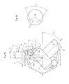
- FIG. 13 illustrates an automotive front drive shaft 20 , to which the fixed type constant velocity universal joint 1 according to this embodiment is applied.
- the fixed type constant velocity universal joint 1 is coupled to one end of an intermediate shaft 11
- a plunging tripod type constant velocity universal joint 15 is coupled to another end thereof.
- bellows boots 16 a and 16 b are mounted and fixed with boot bands 18 a , 18 b , 18 c , and 18 d , respectively.
- Grease is sealed inside the joint as a lubricant.
- FIG. 14 illustrates a first modification of the first embodiment.
- This modification is different from the first embodiment in angle ⁇ that defines the end portion A.
- the angle ⁇ is set to 14°
- the second track groove portion 7 Ab has the curvature center Oo 1
- a curvature radius is formed so as to be larger than that in the first embodiment.
- the position of the end portion A is set so as to occupy 60% of the effective track length on the opening side with respect to the joint center O.
- a track allowance amount U having the same dimension as that in the first embodiment can be secured between the edge portion of the inlet chamfer 10 and a contact point S, and the effective track length is the same as that in the first embodiment. With this, the contact state between the ball 4 and the track groove portion 7 Ab can be sufficiently secured.
- FIG. 15 illustrates a second modification of the first embodiment.
- the angle ⁇ that defines the end portion A is set to 16°
- the second track groove portion 7 Ab has the curvature center Oo 1
- a curvature radius is formed so as to be smaller than that in the first embodiment.
- the position of the end portion A is set so as to occupy 62% of the effective track length on the opening side with respect to the joint center O.
- FIG. 16 is a vertical sectional view as viewed in the plane M comprising the ball raceway center line X of the track groove 7 A and the joint center O as in FIG. 4 (see FIG. 2( a ) ), for illustrating only an outer joint member of the fixed type constant velocity universal joint according to this embodiment. Further, FIG. 16 illustrates an upper half in the radial direction with respect to the axial line of the outer joint member.
- This fixed type constant velocity universal joint is different from the fixed type constant velocity universal joint according to the first embodiment described above in that the curvature center of the arc-shaped ball raceway center line of the first track groove portion is offset in the radial direction with respect to the joint axial line N-N and that a configuration of the straight ball raceway center line of the second track groove portion is adjusted in accordance therewith.
- Other structural details are the same as those in the first embodiment. Also in this embodiment, the parts having the functions similar to those in the first embodiment are represented by the same reference symbols, and redundant description thereof is omitted. The same apples to the embodiments to be described below.
- the end portion A on the opening side of the ball raceway center line Xa of the first track groove portion 7 a of the outer joint member 2 is the same as that in the first embodiment.
- a curvature center O o3 of the ball raceway center line Xa of the first track groove portion 7 a is not offset in the axial direction with respect to the joint center O, but offset by f 2 in the radial direction with respect to the joint axial line.
- the arc-shaped ball raceway center line Xb of the second track groove portion 7 b is adjusted so that the arc-shaped ball raceway center line Xb is connected to the end portion A on the opening side of the ball raceway center line Xa of the first track groove portion 7 a .
- the angle ⁇ that defines the end portion A is set to 15°.
- the track groove depths on the interior side of the joint can be adjusted.
- the ball raceway center line Y of the track groove 9 of the inner joint member 3 is formed so as to be mirror-image symmetrical with the ball raceway center line X of the paired track groove 7 of the outer joint member 2 with respect to the plane P comprising the joint center O at the operating angle of 0°.
- Inclined states of the track grooves 7 and 9 of the outer joint member 2 and the inner joint member 3 in the peripheral direction with respect to the joint axial line N-N, a configuration of the cage 5 , and functions of the joint are the same as those of the fixed type constant velocity universal joint according to the first embodiment. Thus, redundant description thereof is omitted.
- the fixed type constant velocity universal joint according to this embodiment is different from the fixed type constant velocity universal joint according to the first embodiment in that curvature centers of the spherical outer peripheral surface and the spherical inner peripheral surface of the cage are offset in the axial direction with respect to the joint center O.
- Other structural details are the same as those in the first embodiment.
- FIG. 17( a ) is a partial vertical sectional view of the fixed type constant velocity universal joint
- FIG. 17( b ) is a vertical sectional view of the cage
- FIG. 17( a ) also illustrates the track grooves 7 and 9 under a state in which the cross sections taken along the plane M illustrated in FIG. 2( a ) and the plane Q illustrated in FIG. 3( b ) are turned to the inclination angle ⁇ of 0°.
- a curvature center O c1 of the spherical outer peripheral surface 12 and a curvature center O c2 of the spherical inner peripheral surface 13 of the cage 5 are offset in the axial direction by f 3 with respect to the joint center O.
- the thickness of the cage 5 is gradually increased toward the opening side, and hence the strength of the cage 5 can be enhanced particularly at high operating angles.
- the balls 4 arranged in the peripheral direction are temporarily separately positioned between the first track groove portions 7 Aa and 9 Aa ( 7 Ba and 9 Ba; see FIGS. 2( a ) and 3( b ) ) and between the second track groove portions 7 Ab and 9 Ab ( 7 Bb and 9 Bb, see FIGS. 2( a ) and 3( b ) ).
- the pressing forces toward the opening side are applied from the balls 4 positioned between the second track groove portions 7 Ab and 9 Ab ( 7 Bb and 9 Bb) to the pocket portions 5 a of the cage 5 .
- the thickness of the cage 5 is gradually increased toward the opening side, and hence the strength of the cage 5 can be enhanced.
- the track groove depths of the track grooves 7 a and 9 b on the interior side can be increased.
- inclined states of the track grooves 7 and 9 of the outer joint member 2 and the inner joint member 3 in the peripheral direction with respect to the joint axial line N-N, a configuration of the cage 5 , and functions of the joint are the same as those of the fixed type constant velocity universal joint according to the first embodiment. Thus, redundant description thereof is omitted.
- the fixed type constant velocity universal joint according to this embodiment is different from the fixed type constant velocity universal joint according to the first embodiment in the configuration of the second track groove portion. Other structural details are the same as those in the first embodiment.
- the fixed type constant velocity universal joint according to this embodiment has substantially the same shape as that in the first embodiment, including the shape of the second track groove portion.
- FIG. 18 also illustrates the track grooves 7 and 9 under a state in which the cross sections taken along the plane M illustrated in FIG. 2( a ) and the plane Q illustrated in FIG. 3( b ) are turned to the inclination angle ⁇ of 0°.
- the track groove 7 of the outer joint member 2 has the ball raceway center line X, and comprises the first track groove portion 7 a having the arc-shaped ball raceway center line Xa that has the curvature center at the joint center O, and the second track groove portion 7 b having the arc-shaped ball raceway center line Xb that is curved in the opposite direction to that of the first track groove portion 7 a .
- the ball raceway center line Xb of the second track groove portion 7 b is connected smoothly to the ball raceway center line Xa of the first track groove portion 7 a .
- the track groove 9 of the inner joint member 3 has the ball raceway center line Y, and comprises the first track groove portion 9 a having the arc-shaped ball raceway center line Ya that has the curvature center at the joint center O, and the second track groove portion 9 b having the arc-shaped ball raceway center line Yb that is curved in the opposite direction to that of the first track groove portion 9 a .
- the ball raceway center line Yb of the second track groove portion 9 b is connected smoothly to the ball raceway center line Ya of the first track groove portion 9 a.
- the first track groove portion 7 a of the outer joint member 2 has the same shape as that in the first embodiment.
- the ball raceway center line Xb of the second track groove portion 7 b is different from that in the first embodiment.
- the curvature center of the arc-shaped ball raceway center line Xb of the second track groove portion 7 b of the outer joint member 2 is set to a position out in the peripheral direction of the plane M comprising the ball raceway center line X of the track groove and the joint center O (see FIG. 21 ) (not shown).
- the arc-shaped ball raceway center line Xb is set so as to have an appropriate curvature so that the arc-shaped ball raceway center line Xb is connected smoothly to the end portion A on the opening side of the ball raceway center line Xa of the first track groove portion 7 a .
- the ball raceway center line Y of the track groove 9 of the inner joint member 3 is formed so as to be mirror-image symmetrical with the ball raceway center line X of the paired track groove 7 of the outer joint member 2 with respect to the plane P comprising the joint center O at the operating angle of 0°.
- the plane M comprising the ball raceway center line Xa of the first track groove portion 7 Ba and the joint center O is inclined at the angle ⁇ with respect to the joint axial line N-N in the opposite direction to the inclination direction of the first track groove portion 7 Aa.
- the first track groove portions 7 Aa and 7 Ba are formed in the plane M.
- the ball raceway center line Xb of the second track groove portion 7 Ab is connected smoothly to the end portion A on the opening side of the ball raceway center line Xa of the first track groove portion 7 Aa, the ball raceway center line Xb is gently curved in a manner that the inclination angle becomes gradually lower toward the opening side. In this way, the inclination angle of 0° is formed near the opening end portion.
- the ball raceway center line Xb of the second track groove portion 7 Bb which is inclined in the opposite direction, is formed in the same way.
- the plane Q comprising the ball raceway center line Ya of the first track groove portion 9 Ba and the joint center O is inclined at the angle ⁇ with respect to the joint axial line N-N in the opposite direction to the inclination direction of the first track groove portion 9 Aa.
- the ball raceway center line Yb of the second track groove portion 9 Ab of the inner joint member 3 is connected smoothly to the end portion B on the interior side of the ball raceway center line Ya of the first track groove portion 9 Aa, the ball raceway center line Yb is gently curved in a manner that the inclination angle becomes gradually lower toward the interior side. In this way, the inclination angle of 0° is formed near the interior end portion.
- the ball raceway center line Yb of the second track groove portion 9 Bb which is inclined in the opposite direction, is formed in the same way.
- the second track groove portions 7 Ab and 7 Bb of the outer joint member 2 and the second track groove portions 9 Ab and 9 Bb of the inner joint member 3 are formed as described above.
- the intervals on the approaching side between the second track groove portions 7 Ab and 7 Bb and the second track groove portions 9 Ab and 9 Bb, which are adjacent to each other in the peripheral direction, and the intervals on the separating side are reduced therebetween.
- differences between the intervals can be reduced in the peripheral direction.
- a difference in contact area on the opening side between the respective regions of the spherical inner peripheral surface 6 of the outer joint member 2 , and a difference in contact area on the interior side between the respective regions of the spherical outer peripheral surface 8 of the inner joint member 3 can be reduced.
- the spherical contact portions between the cage 5 and the outer joint member 2 , and between the cage 5 and the inner joint member 3 can be arranged in a balanced manner. As a result, further smoother operability can be achieved.
- the ball raceway center line Xb of each of the second track groove portions 7 Ab and 7 Bb of the outer joint member 2 is connected smoothly to the end portion A on the opening side of the ball raceway center line Xa of each of the first track groove portions 7 Aa and 7 Ba, the ball raceway center line Xb is gently curved in a manner that the inclination angle ⁇ becomes gradually lower toward the opening side. In this way, the inclination angle ⁇ of 0° is formed near the opening end portion.
- the ball raceway center line Yb of the second track groove portions 9 Ab and 9 Bb of the inner joint member 3 is connected smoothly to the end portion B on the interior side of the ball raceway center line Ya of each of the first track groove portions 9 Aa and 9 Ba, the ball raceway center line Yb is gently curved in a manner that the inclination angle ⁇ becomes gradually lower toward the interior side. In this way, the inclination angle ⁇ of 0° is formed near the interior end portion.
- the present invention is not limited thereto.
- the inclination angle ⁇ of 0° may be formed on the opening side.
- the inclination angle ⁇ of 0° may be formed on the interior side.
- the number of the balls 4 is eight. However, the present invention is not limited thereto. Ten balls are also preferred, and twelve balls may also be appropriately applicable.
- first track groove portions of the fixed type constant velocity universal joints are not limited to a single arc, but may be formed of a plurality of arcs in consideration of the track groove depths and the like. Still further, in the above description, the track grooves are arranged at a regular pitch in the peripheral direction, but the track grooves may be arranged at an irregular pitch. Yet further, in the above description, the inclination angles ⁇ of the first track grooves with respect to the joint axial line N-N are equal to each other in all the track grooves. However, the present invention is not limited thereto. The first track grooves of the outer joint member and the inner joint member may be formed so as to have inclination angles ⁇ that are unequal from pair to pair.
- the track grooves and the balls are held in angular contact at a contact angle.
- the track grooves may be formed into a circular shape in horizontal cross section so that the track grooves and the balls are held in circular contact.
Landscapes
- Engineering & Computer Science (AREA)
- General Engineering & Computer Science (AREA)
- Mechanical Engineering (AREA)
- Rolling Contact Bearings (AREA)
Abstract
Description
- Patent Document 1: JP 2009-250365 A
(2τ)=(2τ′)cos δ+(2γ)sin δ
where δ is contact angles between one of the plurality of balls and corresponding one of the plurality of track grooves of the outer joint member and between the one of the plurality of balls and corresponding one of the plurality of track grooves of the inner joint member, and γ is an inclination angle of the corresponding one of the plurality of track grooves of the outer joint member and the corresponding one of the plurality of track grooves of the inner joint member. With this, parameters of the plurality of track grooves of the outer joint member and the plurality of track grooves of the inner joint member can be determined based on the wedge angle 2τ′ in two-dimensional cross section at the phase angle φ of 0°. Thus, work of setting the parameters of the plurality of track grooves of the outer joint member and the plurality of track grooves of the inner joint member can be markedly simplified. Further, such setting of the parameters enables strength and durability at the maximum operating angle to be secured equivalently to those of widely available related-art constant velocity universal joints.
(2τ)=(2τ′)cos δ+(2γ)sin δ (1)
Note that, this approximate equation is established only in two-dimensional cross section in which the cross sections taken along the plane M and the plane Q at the phase angle φ of 0° are turned to the inclination angle γ of 0°.
-
- 1 fixed type constant velocity universal joint
- 2 outer joint member
- 3 inner joint member
- 4 ball
- 5 cage
- 6 spherical inner peripheral surface
- 7 track groove
- 7 a first track groove portion
- 7 b second track groove portion
- 8 spherical outer peripheral surface
- 9 track groove
- 9 a first track groove
- 9 b second track groove
- 11 shaft
- 12 spherical outer peripheral surface
- 13 spherical inner peripheral surface
- 20 drive shaft
- A end portion
- B end portion
- f2 offset amount
- K perpendicular line
- L straight line
- M plane including ball raceway center line
- N joint axial line
- O joint center
- P joint center plane
- Q plane including ball raceway center line
- Oo1 curvature center
- Oi1 curvature center
- Oo3 curvature center
- R straight line
- X ball raceway center line
- Y ball raceway center line
- β angle
- γ inclination angle
- δ contact angle
- θ operating angle
- σ allowance amount
Claims (19)
(2τ′)cos δ+(2γ)sin δ≦43°
(2τ′)cos δ+(2γ)sin δ≦43°
Applications Claiming Priority (3)
| Application Number | Priority Date | Filing Date | Title |
|---|---|---|---|
| JP2011274436A JP5936855B2 (en) | 2011-12-15 | 2011-12-15 | Fixed constant velocity universal joint |
| JP2011-274436 | 2011-12-15 | ||
| PCT/JP2012/079832 WO2013088905A1 (en) | 2011-12-15 | 2012-11-16 | Fixed constant velocity universal joint |
Publications (2)
| Publication Number | Publication Date |
|---|---|
| US20140329608A1 US20140329608A1 (en) | 2014-11-06 |
| US9464674B2 true US9464674B2 (en) | 2016-10-11 |
Family
ID=48612360
Family Applications (1)
| Application Number | Title | Priority Date | Filing Date |
|---|---|---|---|
| US14/362,659 Active US9464674B2 (en) | 2011-12-15 | 2012-11-16 | Fixed type constant velocity universal joint |
Country Status (5)
| Country | Link |
|---|---|
| US (1) | US9464674B2 (en) |
| EP (1) | EP2792896B1 (en) |
| JP (1) | JP5936855B2 (en) |
| CN (1) | CN103987980B (en) |
| WO (1) | WO2013088905A1 (en) |
Cited By (1)
| Publication number | Priority date | Publication date | Assignee | Title |
|---|---|---|---|---|
| US20190383330A1 (en) * | 2018-06-15 | 2019-12-19 | Steering Solutions Ip Holding Corporation | High efficiency cvj with asymetric opposed tracks |
Families Citing this family (7)
| Publication number | Priority date | Publication date | Assignee | Title |
|---|---|---|---|---|
| US9163672B2 (en) * | 2011-05-30 | 2015-10-20 | Ntn Corporation | Fixed constant velocity universal joint |
| JP5882050B2 (en) * | 2011-12-27 | 2016-03-09 | Ntn株式会社 | Fixed constant velocity universal joint |
| JP6690415B2 (en) * | 2016-06-06 | 2020-04-28 | 株式会社ジェイテクト | Constant velocity joint and manufacturing method thereof |
| JP7139269B2 (en) * | 2018-04-03 | 2022-09-20 | Ntn株式会社 | Fixed type constant velocity universal joint |
| DE102018126976B4 (en) | 2018-10-29 | 2021-05-12 | Neapco Intellectual Property Holdings, Llc | Constant velocity ball joint with multi-cage window |
| CN109404430A (en) * | 2018-11-06 | 2019-03-01 | 浙江向隆机械有限公司 | A kind of fixed universal joint |
| CN114668452A (en) * | 2022-04-25 | 2022-06-28 | 天衍医疗器材有限公司 | A double-curved acetabular reamer holder suitable for robotic surgery |
Citations (15)
| Publication number | Priority date | Publication date | Assignee | Title |
|---|---|---|---|---|
| CN1248316A (en) | 1997-02-21 | 2000-03-22 | Gkn洛布罗有限公司 | Constant velocity turning joint |
| WO2001061203A2 (en) | 2000-02-16 | 2001-08-23 | Delphi Technologies, Inc. | Constant velocity joint having fixed center and crossed grooves |
| JP2004332815A (en) | 2003-05-07 | 2004-11-25 | Ntn Corp | Fixed type constant speed universal joint |
| JP2007218353A (en) | 2006-02-16 | 2007-08-30 | Ntn Corp | Fixed type constant velocity universal joint |
| JP2008069889A (en) | 2006-09-14 | 2008-03-27 | Ntn Corp | Fixed type constant velocity universal joint |
| CN101517255A (en) | 2006-09-14 | 2009-08-26 | Ntn株式会社 | Fixed constant velocity universal joint |
| CN101542149A (en) | 2006-10-13 | 2009-09-23 | Gkn动力传动系统国际有限责任公司 | Constant velocity ball joint in the form of a counter track joint |
| JP2009250365A (en) | 2008-04-08 | 2009-10-29 | Ntn Corp | Constant velocity universal joint |
| CN101627218A (en) | 2006-12-29 | 2010-01-13 | Gkn动力传动系统国际有限责任公司 | Cage Offset Joint Set |
| US20100029396A1 (en) | 2006-09-14 | 2010-02-04 | Teruaki Fujio | Fixed constant-velocity universal joint |
| US20100292016A1 (en) | 2009-05-13 | 2010-11-18 | Hans Wormsbaecher | Plunging cross-track constant velocity joint |
| WO2011043268A1 (en) | 2009-10-08 | 2011-04-14 | Ntn株式会社 | Fixed type constant velocity universal joint |
| US20140243104A1 (en) * | 2011-11-11 | 2014-08-28 | Ntn Corporation | Fixed type constant-velocity universal joint |
| US20150240878A1 (en) * | 2012-10-12 | 2015-08-27 | Ntn Corporation | Fixed type constant velocity universal joint |
| US9163672B2 (en) * | 2011-05-30 | 2015-10-20 | Ntn Corporation | Fixed constant velocity universal joint |
-
2011
- 2011-12-15 JP JP2011274436A patent/JP5936855B2/en active Active
-
2012
- 2012-11-16 WO PCT/JP2012/079832 patent/WO2013088905A1/en not_active Ceased
- 2012-11-16 CN CN201280061839.5A patent/CN103987980B/en active Active
- 2012-11-16 US US14/362,659 patent/US9464674B2/en active Active
- 2012-11-16 EP EP12858265.7A patent/EP2792896B1/en active Active
Patent Citations (20)
| Publication number | Priority date | Publication date | Assignee | Title |
|---|---|---|---|---|
| US6319133B1 (en) | 1997-02-21 | 2001-11-20 | Gkn Lobro Gmbh | Constant velocity universal joint |
| CN1248316A (en) | 1997-02-21 | 2000-03-22 | Gkn洛布罗有限公司 | Constant velocity turning joint |
| WO2001061203A2 (en) | 2000-02-16 | 2001-08-23 | Delphi Technologies, Inc. | Constant velocity joint having fixed center and crossed grooves |
| US20010046900A1 (en) | 2000-02-16 | 2001-11-29 | Song Zexi J. | Constant velocity joint having fixed center and crossed grooves |
| JP2004332815A (en) | 2003-05-07 | 2004-11-25 | Ntn Corp | Fixed type constant speed universal joint |
| JP2007218353A (en) | 2006-02-16 | 2007-08-30 | Ntn Corp | Fixed type constant velocity universal joint |
| US20100029396A1 (en) | 2006-09-14 | 2010-02-04 | Teruaki Fujio | Fixed constant-velocity universal joint |
| JP2008069889A (en) | 2006-09-14 | 2008-03-27 | Ntn Corp | Fixed type constant velocity universal joint |
| CN101517255A (en) | 2006-09-14 | 2009-08-26 | Ntn株式会社 | Fixed constant velocity universal joint |
| CN101542149A (en) | 2006-10-13 | 2009-09-23 | Gkn动力传动系统国际有限责任公司 | Constant velocity ball joint in the form of a counter track joint |
| US20100113167A1 (en) | 2006-10-13 | 2010-05-06 | Thomas Weckerling | Constant velocity ball joint in the form of a counter track joint |
| CN101627218A (en) | 2006-12-29 | 2010-01-13 | Gkn动力传动系统国际有限责任公司 | Cage Offset Joint Set |
| US20100323802A1 (en) | 2006-12-29 | 2010-12-23 | Thomas Weckerling | Joint arrangement with cage offset |
| JP2009250365A (en) | 2008-04-08 | 2009-10-29 | Ntn Corp | Constant velocity universal joint |
| US20100292016A1 (en) | 2009-05-13 | 2010-11-18 | Hans Wormsbaecher | Plunging cross-track constant velocity joint |
| WO2011043268A1 (en) | 2009-10-08 | 2011-04-14 | Ntn株式会社 | Fixed type constant velocity universal joint |
| US20120165105A1 (en) | 2009-10-08 | 2012-06-28 | Teruaki Fujio | Fixed type constant velocity universal joint |
| US9163672B2 (en) * | 2011-05-30 | 2015-10-20 | Ntn Corporation | Fixed constant velocity universal joint |
| US20140243104A1 (en) * | 2011-11-11 | 2014-08-28 | Ntn Corporation | Fixed type constant-velocity universal joint |
| US20150240878A1 (en) * | 2012-10-12 | 2015-08-27 | Ntn Corporation | Fixed type constant velocity universal joint |
Non-Patent Citations (4)
| Title |
|---|
| Chinese Office Action issued Nov. 25, 2015 in counterpart Chinese Patent Application No. 201280061839.5 with English translation. |
| Extended European Search Report issued Jul. 5, 2016 in corresponding European Application No. 12858265.7. |
| International Preliminary Report on Patentability and Written Opinion of the International Searching Authority issued Jun. 26, 2014 in International (PCT) Application No. PCT/JP2012/079832. |
| International Search Report issued Jan. 15, 2013 in International (PCT) Application No. PCT/JP2012/079832. |
Cited By (2)
| Publication number | Priority date | Publication date | Assignee | Title |
|---|---|---|---|---|
| US20190383330A1 (en) * | 2018-06-15 | 2019-12-19 | Steering Solutions Ip Holding Corporation | High efficiency cvj with asymetric opposed tracks |
| US12234864B2 (en) * | 2018-06-15 | 2025-02-25 | Steering Solutions Ip Holding Corporation | Constant velocity joint with asymmetric opposed tracks |
Also Published As
| Publication number | Publication date |
|---|---|
| CN103987980A (en) | 2014-08-13 |
| WO2013088905A1 (en) | 2013-06-20 |
| CN103987980B (en) | 2016-11-09 |
| EP2792896A4 (en) | 2016-08-03 |
| JP2013124729A (en) | 2013-06-24 |
| EP2792896B1 (en) | 2021-01-06 |
| EP2792896A1 (en) | 2014-10-22 |
| US20140329608A1 (en) | 2014-11-06 |
| JP5936855B2 (en) | 2016-06-22 |
Similar Documents
| Publication | Publication Date | Title |
|---|---|---|
| US9464674B2 (en) | Fixed type constant velocity universal joint | |
| US9206855B2 (en) | Fixed type constant-velocity universal joint | |
| US9169877B2 (en) | Fixed constant velocity universal joint | |
| US9163672B2 (en) | Fixed constant velocity universal joint | |
| EP2905491B1 (en) | Fixed type constant-velocity universal joint | |
| US9581206B2 (en) | Fixed type constant velocity universal joint | |
| US9410581B2 (en) | Fixed type constant velocity universal joint | |
| US9551382B2 (en) | Fixed type constant velocity universal joint | |
| EP3067582B1 (en) | Stationary constant velocity universal joint | |
| US11053986B2 (en) | Fixed type constant velocity universal joint | |
| US11927226B2 (en) | Fixed type constant velocity universal joint | |
| CN103917796B (en) | Fixed-type constant-velocity Hooks coupling universal coupling |
Legal Events
| Date | Code | Title | Description |
|---|---|---|---|
| AS | Assignment |
Owner name: NTN CORPORATION, JAPAN Free format text: ASSIGNMENT OF ASSIGNORS INTEREST;ASSIGNORS:YAMAZAKI, KISAO;YAMAZAKI, KENTA;HIRUKAWA, HIROYASU;SIGNING DATES FROM 20140609 TO 20140612;REEL/FRAME:033154/0836 |
|
| STCF | Information on status: patent grant |
Free format text: PATENTED CASE |
|
| MAFP | Maintenance fee payment |
Free format text: PAYMENT OF MAINTENANCE FEE, 4TH YEAR, LARGE ENTITY (ORIGINAL EVENT CODE: M1551); ENTITY STATUS OF PATENT OWNER: LARGE ENTITY Year of fee payment: 4 |
|
| MAFP | Maintenance fee payment |
Free format text: PAYMENT OF MAINTENANCE FEE, 8TH YEAR, LARGE ENTITY (ORIGINAL EVENT CODE: M1552); ENTITY STATUS OF PATENT OWNER: LARGE ENTITY Year of fee payment: 8 |