US9460895B2 - Gas supply method for semiconductor manufacturing apparatus, gas supply system, and semiconductor manufacturing apparatus - Google Patents
Gas supply method for semiconductor manufacturing apparatus, gas supply system, and semiconductor manufacturing apparatus Download PDFInfo
- Publication number
- US9460895B2 US9460895B2 US14/377,898 US201314377898A US9460895B2 US 9460895 B2 US9460895 B2 US 9460895B2 US 201314377898 A US201314377898 A US 201314377898A US 9460895 B2 US9460895 B2 US 9460895B2
- Authority
- US
- United States
- Prior art keywords
- gas
- valve
- pipe
- gas supply
- etching
- Prior art date
- Legal status (The legal status is an assumption and is not a legal conclusion. Google has not performed a legal analysis and makes no representation as to the accuracy of the status listed.)
- Active
Links
Images


Classifications
-
- H—ELECTRICITY
- H01—ELECTRIC ELEMENTS
- H01J—ELECTRIC DISCHARGE TUBES OR DISCHARGE LAMPS
- H01J37/00—Discharge tubes with provision for introducing objects or material to be exposed to the discharge, e.g. for the purpose of examination or processing thereof
- H01J37/32—Gas-filled discharge tubes
- H01J37/32431—Constructional details of the reactor
- H01J37/3244—Gas supply means
-
- H01L21/3065—
-
- H01L21/30655—
-
- H01L21/76898—
-
- H01L22/26—
-
- H01L29/84—
-
- H—ELECTRICITY
- H10—SEMICONDUCTOR DEVICES; ELECTRIC SOLID-STATE DEVICES NOT OTHERWISE PROVIDED FOR
- H10D—INORGANIC ELECTRIC SEMICONDUCTOR DEVICES
- H10D48/00—Individual devices not covered by groups H10D1/00 - H10D44/00
- H10D48/50—Devices controlled by mechanical forces, e.g. pressure
-
- H—ELECTRICITY
- H10—SEMICONDUCTOR DEVICES; ELECTRIC SOLID-STATE DEVICES NOT OTHERWISE PROVIDED FOR
- H10P—GENERIC PROCESSES OR APPARATUS FOR THE MANUFACTURE OR TREATMENT OF DEVICES COVERED BY CLASS H10
- H10P50/00—Etching of wafers, substrates or parts of devices
- H10P50/20—Dry etching; Plasma etching; Reactive-ion etching
- H10P50/24—Dry etching; Plasma etching; Reactive-ion etching of semiconductor materials
- H10P50/242—Dry etching; Plasma etching; Reactive-ion etching of semiconductor materials of Group IV materials
- H10P50/244—Dry etching; Plasma etching; Reactive-ion etching of semiconductor materials of Group IV materials comprising alternated and repeated etching and passivation steps
-
- H—ELECTRICITY
- H10—SEMICONDUCTOR DEVICES; ELECTRIC SOLID-STATE DEVICES NOT OTHERWISE PROVIDED FOR
- H10P—GENERIC PROCESSES OR APPARATUS FOR THE MANUFACTURE OR TREATMENT OF DEVICES COVERED BY CLASS H10
- H10P74/00—Testing or measuring during manufacture or treatment of wafers, substrates or devices
- H10P74/23—Testing or measuring during manufacture or treatment of wafers, substrates or devices characterised by multiple measurements, corrections, marking or sorting processes
- H10P74/238—Testing or measuring during manufacture or treatment of wafers, substrates or devices characterised by multiple measurements, corrections, marking or sorting processes comprising acting in response to an ongoing measurement without interruption of processing, e.g. endpoint detection or in-situ thickness measurement
-
- H—ELECTRICITY
- H10—SEMICONDUCTOR DEVICES; ELECTRIC SOLID-STATE DEVICES NOT OTHERWISE PROVIDED FOR
- H10W—GENERIC PACKAGES, INTERCONNECTIONS, CONNECTORS OR OTHER CONSTRUCTIONAL DETAILS OF DEVICES COVERED BY CLASS H10
- H10W20/00—Interconnections in chips, wafers or substrates
- H10W20/01—Manufacture or treatment
- H10W20/021—Manufacture or treatment of interconnections within wafers or substrates
- H10W20/023—Manufacture or treatment of interconnections within wafers or substrates the interconnections being through-semiconductor vias
- H10W20/0245—Manufacture or treatment of interconnections within wafers or substrates the interconnections being through-semiconductor vias comprising use of blind vias during the manufacture
-
- H—ELECTRICITY
- H10—SEMICONDUCTOR DEVICES; ELECTRIC SOLID-STATE DEVICES NOT OTHERWISE PROVIDED FOR
- H10W—GENERIC PACKAGES, INTERCONNECTIONS, CONNECTORS OR OTHER CONSTRUCTIONAL DETAILS OF DEVICES COVERED BY CLASS H10
- H10W20/00—Interconnections in chips, wafers or substrates
- H10W20/20—Interconnections within wafers or substrates, e.g. through-silicon vias [TSV]
- H10W20/211—Through-semiconductor vias, e.g. TSVs
- H10W20/212—Top-view shapes or dispositions, e.g. top-view layouts of the vias
- H10W20/2125—Top-view shapes
-
- Y—GENERAL TAGGING OF NEW TECHNOLOGICAL DEVELOPMENTS; GENERAL TAGGING OF CROSS-SECTIONAL TECHNOLOGIES SPANNING OVER SEVERAL SECTIONS OF THE IPC; TECHNICAL SUBJECTS COVERED BY FORMER USPC CROSS-REFERENCE ART COLLECTIONS [XRACs] AND DIGESTS
- Y10—TECHNICAL SUBJECTS COVERED BY FORMER USPC
- Y10T—TECHNICAL SUBJECTS COVERED BY FORMER US CLASSIFICATION
- Y10T137/00—Fluid handling
- Y10T137/8593—Systems
- Y10T137/87571—Multiple inlet with single outlet
- Y10T137/87676—With flow control
- Y10T137/87684—Valve in each inlet
Definitions
- the present invention relates to a gas supply method for a semiconductor manufacturing apparatus, a gas supply system, and a semiconductor manufacturing apparatus.
- 3D packaging technique that involves stacking semiconductor chips to increase the density per unit area of semiconductor devices.
- An example of the 3D packaging technique includes 3D circuitization, which involves establishing electrical connection between semiconductor chips stacked on each other using an electrode formed at a through hole (TSV: through-silicon via) penetrating through a semiconductor chip.
- TSV through-silicon via
- An etching process for etching a deep hole penetrating through the semiconductor chip has to be performed in such case.
- a plasma processing method that involves temporarily and intermittently stopping the supply of SF 6 gas that encourages etching for a short period of time and forming a nitride film on a surface of a silicon substrate while the etching process is temporarily stopped in order to etch the silicon substrate without the occurrence of undercutting (see e.g. Patent Document 1).
- a plasma processing method that involves alternately repeating a deposition step of performing a plasma process on a substrate by supplying a gas having a high deposition gas content and an etching step of performing a plasma process on the substrate by supplying gas with a high etching gas content (see e.g. Patent Document 2).
- the selectivity of the substrate with respect to the resist film may be higher compared to the case of performing a normal plasma etching process, and a desired etching shape may be efficiently formed while maintaining a relatively high etch rate.
- a gas to be used in a next step is introduced while discharging a gas used in a previous step immediately preceding the next step at a switch timing for switching between the deposition step and the etching step. That is, gas is introduced into a chamber after passing through a gas supply pipe and being diffused at a diffusion chamber.
- a processing gas used in a previous step remains within the diffusion chamber and is mixed with a processing gas to be used in the next step that is newly introduced into the diffusion chamber.
- variations occur in the component ratios of the processing gases.
- the amount of residual gas of a previous process remaining in the diffusion chamber varies depending on process conditions such as the pressure within a processing chamber, for example.
- process conditions such as the pressure within a processing chamber, for example.
- an aspect of the present invention relates to additionally performing a step of controlling the pressure of a processing gas within a gas supply pipe in a plasma process of repeatedly performing a deposition step and an etching step to thereby provide a gas supply method for a semiconductor manufacturing apparatus, a gas supply system, and a semiconductor manufacturing apparatus that are capable of preventing the mixing of residual gas components remaining in the gas supply pipe from a previous step with a processing gas that is newly supplied for a next step.
- a gas supply method for a semiconductor manufacturing apparatus that alternately repeats a first step of performing a plasma process on a workpiece by supplying a first gas into a chamber via a first gas pipe and a diffusion chamber, and a second step of performing a plasma process on the workpiece by supplying a second gas into the chamber via a second gas supply pipe and the diffusion chamber.
- the gas supply method involves controlling communication between the first gas pipe and a diffusion chamber using a first valve, controlling communication between the second gas pipe and the diffusion chamber using a second valve, controlling discharge of gas within the first gas pipe using a third valve connected upstream from the first valve of the first gas pipe, controlling discharge of gas within the second gas pipe using a fourth valve connected upstream from the second valve of the second gas pipe, and controlling communication between an exhaust pipe and the diffusion chamber using a fifth valve.
- the gas supply method further includes a first pressurization step of closing the first valve and closing the third valve before starting the first step, and increasing a pressure within the first gas pipe by the first gas; a second pressurization step of closing the second valve and closing the fourth valve before starting the second step, and increasing a pressure within the second gas pipe by the second gas; and an exhaust step of opening the fifth valve in response to a start of the first step and a start of the second step, and discharging gas within the diffusion chamber.
- a gas supply system for a semiconductor manufacturing apparatus that alternately repeats a first step of performing a plasma process on a workpiece by supplying a first gas into a chamber via a first gas pipe and a diffusion chamber, and a second step of performing a plasma process on the workpiece by supplying a second gas into the chamber via a second gas supply pipe and the diffusion chamber.
- the gas supply system includes a first valve configured to control communication between the first gas pipe and a diffusion chamber, a second valve configured to control communication between the second gas pipe and the diffusion chamber, a third valve connected upstream from the first valve of the first gas pipe and configured to control discharge of gas within the first gas pipe, a fourth valve connected upstream from the second valve of the second gas pipe and configured to control discharge of gas within the second gas pipe, and a fifth valve configured to control communication between an exhaust pipe and the diffusion chamber.
- the gas supply system further includes a first gas supply mechanism configured to close the first valve and close the third valve before starting the first step, and increase a pressure within the first gas pipe by the first gas; a second gas supply mechanism configured to close the second valve and close the fourth valve before starting the second step, and increase a pressure within the second gas pipe by the second gas; and an exhaust mechanism configured to open the fifth valve in response to a start of the first step and a start of the second step, and discharge gas within the diffusion chamber.
- a first gas supply mechanism configured to close the first valve and close the third valve before starting the first step, and increase a pressure within the first gas pipe by the first gas
- a second gas supply mechanism configured to close the second valve and close the fourth valve before starting the second step, and increase a pressure within the second gas pipe by the second gas
- an exhaust mechanism configured to open the fifth valve in response to a start of the first step and a start of the second step, and discharge gas within the diffusion chamber.
- a semiconductor manufacturing apparatus that performs a plasma process on the workpiece using the gas supply system according to an embodiment of the present invention.
- the present invention by additionally performing a step of controlling the pressure of a processing gas within a gas supply pipe (pressurization step and exhaust step) in a plasma process of repeatedly performing a deposition step and an etching step, residual gas components remaining in the gas supply pipe from a previous step may be prevented from mixing with a processing gas newly supplied for a next step, and the switch time for switching processing gases of the steps may be reduced.
- FIG. 1 illustrates an overall configuration of a gas supply system according to an embodiment of the present invention
- FIG. 2 illustrates a gas flow of the gas supply system according to an embodiment of the present invention
- FIG. 3 is a flowchart illustrating a plasma process of repeatedly performing a deposition step and an etching step using the gas supply system according to an embodiment of the present invention
- FIG. 4 is a sequence chart illustrating the plasma process of repeatedly performing a deposition step and an etching step using the gas supply system according to an embodiment of the present invention
- FIG. 5 illustrates variables indicating states within the gas supply system according to an embodiment of the present invention
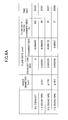
- FIG. 6A is a table illustrating a relationship between a pipe diameter and the discharge of gas in the gas supply system according to an embodiment of the present invention
- FIG. 6B is a graph illustrating the relationship between the pipe diameter and the discharge of gas in the gas supply system according to an embodiment of the present invention.
- FIG. 7 illustrates a pressure within a diffusion chamber, a molar flow rate of gas flowing toward an exhaust line, and a molar flow rate of gas flowing toward a chamber after switching steps in the gas supply system according to an embodiment of the present invention
- FIG. 8 illustrates experimental results of implementing a pressurization step according an embodiment of the present invention
- FIG. 9 illustrates experimental results of implementing an exhaust step according an embodiment of the present invention.
- FIG. 10 is a graphical representation of the experimental results of implementing the pressurization step and the exhaust step according to an embodiment of the present invention.
- FIG. 11 illustrates experimental results of implementing a plasma process of repeatedly performing a deposition step and an etching step according to an embodiment of the present invention
- FIG. 12 illustrates a semiconductor manufacturing apparatus that uses the gas supply system according to an embodiment of the present invention
- FIG. 13 is a horizontal cross-sectional view of a dipole ring magnet according to an embodiment of the present invention.
- FIG. 14 illustrates an application example of the plasma process of repeatedly performing a deposition step and an etching step according to an embodiment of the present invention
- FIG. 15 is a graph illustrating an exemplary plasma emission intensity in the plasma process of repeatedly performing a deposition step and an etching step according to an embodiment of the present invention.
- FIG. 16 illustrates exemplary etching results of the plasma process of repeatedly performing a deposition step and an etching step according to an embodiment of the present invention.
- a pressure of 1 Torr may be converted into 133.322 Pa.
- FIG. 15 is a graph illustrating an exemplary plasma emission intensity in a plasma process of repeatedly performing a deposition step and an etching step according to an embodiment of the present invention.
- FIG. 16 illustrates an exemplary etching result of the plasma process of repeatedly performing a deposition step and an etching step according to an embodiment of the present invention.
- a deposition step of introducing a gas containing a greater proportion of a deposition gas compared to an etching gas and an etching step of introducing a gas containing a greater proportion of the etching gas compared to the deposition gas are alternately performed at approximately 10-second-intervals. Also, in the process of repeatedly performing the deposition step and the etching step as illustrated in FIG. 15 , a transition point from the deposition step to the etching step or vice versa and a change point of the plasma emission intensity are intentionally shifted from each other.
- plasma generation conditions are controlled such that even when the process transitions from the deposition step to the etching step, the plasma emission intensity of the deposition step is maintained a while longer, for example.
- plasma generation conditions are controlled such that even when the process transitions from the etching step to the deposition step, the plasma emission intensity of the etching step is maintained a while longer, for example.
- various transient states of plasma may be intentionally created, for example.
- the switch timings of the plasma emission intensity are arranged to match the switch timings of the deposition step and the etching step.
- the exemplary etching results of implementing the plasma process of repeatedly performing a deposition step and an etching step according to an embodiment of the present invention as illustrated in FIG. 16 are described.
- the plasma process of repeatedly performing a deposition step and an etching step is performed under the following process conditions.
- FIG. 16 illustrates etching results obtained by implementing the plasma process of repeatedly performing a deposition step and an etching step under the above process conditions using gas mixtures with differing mixture ratios A and B.
- the mixture ratio A represents a case where the gas mixture is 91% deposition gas (film deposition gas) and 9% etching gas.
- a protective film having an adequate film thickness of 0.873 ⁇ m was formed.
- the mixture ratio B represents a case where the gas mixture is 80% deposition gas (film deposition gas) and 20% etching gas.
- the film thickness of the protective film was 0.446 ⁇ m. That is, when the deposition gas ratio was reduced from 91% to 80%, the film thickness of the resulting protective film was reduced by approximately 45%.
- the bottom of a hole may be arranged to have a desired shape, whereas in the case of using the gas mixture ratio B as illustrated on the right side of FIG. 16 , etching tends to progress at the bottom of the hole.
- the plasma process of repeatedly performing a deposition step and an etching step is implemented using a gas mixture ratio of 80% deposition gas (film deposition gas) and 20% etching gas, the film thickness of a film may be too thin to adequately serve its function as a protective film.
- the etch rate may be no more than 3 ⁇ m/min indicating a degradation in etching performance.
- etching performance may be improved and a desirable etching shape may presumably be obtained by a gas supply method that can reduce the switch time for switching between the above two steps and prevent the mixing of the processing gases of the above two steps as much as possible.
- a gas supply system according to an embodiment of the present invention described below, the following features (1)-(3) are implemented in order to reduce the switch time for switching between the above two steps.
- a gas supply line is provided as a path from a gas supply source to a diffusion chamber, the gas supply line including a first gas supply mechanism for supplying a deposition main gas (first gas containing a deposition gas at a higher ratio than an etching gas) into a chamber and a second gas supply mechanism for supplying an etching main gas (second gas containing the etching gas at a higher ratio than the deposition gas) into the chamber.
- a deposition main gas first gas containing a deposition gas at a higher ratio than an etching gas
- second gas supply mechanism for supplying an etching main gas (second gas containing the etching gas at a higher ratio than the deposition gas) into the chamber.
- a valve controlled by a controller is arranged at each gas supply line, and a pipeline pressure of the gas supply line is controlled by opening/closing the valve.
- the valve is closed before gas is supplied to the chamber, and the pipeline pressure of the gas supply line is increased to create a pressure gradient with respect to the pressure within the chamber.
- gas may be quickly transported into the diffusion chamber of the gas chamber owing to the pressure gradient. Also, residual gas from a previous step remaining within the diffusion chamber may be pushed out at this point.
- an exhaust line is provided for efficiently exchanging the residual gas from the previous step remaining within the diffusion chamber.
- gases used in the deposition step and the etching step in the process of repeatedly performing the above two steps may hardly be mixed with one another upon switching between the steps.
- a film deposition process for forming a protective film and an etching process may be efficiently performed in the deposition step and the etching step, respectively, and the performance of the deposition step and the performance of the etching step may be improved.
- the cycle length of the plasma process of repeatedly performing the deposition step and the etching step may be shortened, the etch rate and the selectivity of a silicon substrate with respect to a resist film may be increased, and a desirable etching shape may be obtained.
- the gas supply system according to an embodiment of the present invention is described in greater detail.
- the gas supply system 10 is used by a semiconductor manufacturing apparatus 30 .
- the semiconductor manufacturing apparatus 30 executes a plasma process of alternately performing a deposition step and an etching step a predetermined number of times.
- the deposition step involves supplying a deposition main gas containing a deposition gas at a higher ratio than an etching gas (first gas) into a chamber C through a diffusion chamber 16 a and performing a plasma process on a silicon substrate W.
- the etching step involves supplying an etching main gas containing the etching gas at a higher ratio compared to the deposition gas (second gas) into the chamber C through the diffusion chamber 16 a and performing a plasma process on the silicon substrate W.
- the deposition main gas is a gas mixture containing SiF 4 gas and O 2 gas.
- the etching main gas is a gas mixture containing SF 6 gas and O 2 gas.
- the gas supply system 10 includes a gas adjustment unit 115 b .
- the gas adjustment unit 115 b is connected to a gas supply source 20 , the semiconductor manufacturing apparatus 30 , a controller 60 , and an exhaust device 115 c.
- the gas adjustment unit 115 b includes a first gas supply mechanism F 1 as a gas supply line for the deposition step and a second gas supply mechanism F 2 as a gas supply line for the etching step.
- the deposition main gas is supplied to the chamber C in the deposition step by the first gas supply mechanism F 1 .
- the etching main gas is supplied to the chamber C in the etching step by the second gas supply mechanism F 2 .
- the gas adjustment unit 115 b alternately supplies the deposition main gas and the etching main gas from the gas supply source 20 to the semiconductor manufacturing apparatus 30 at predetermined timings.
- the gas adjustment unit 115 b also includes an exhaust mechanism F 3 as a gas exhaust line in addition to the first gas supply mechanism F 1 and the second gas supply mechanism F 2 .
- the first gas supply mechanism F 1 includes a first gas supply pipe 41 , a first gas introducing pipe 42 , and a first valve 11 .
- the first gas supply pipe 41 is a pipe for supplying the deposition main gas that is controlled to a predetermined flow rate by a flow control system (FCS) 21 arranged at the gas supply source 20 .
- a first bypass pipe 45 is connected to the first gas supply pipe 41 via a third valve 13 .
- the first bypass pipe 45 bypasses the deposition main gas and discharges the deposition main gas.
- An orifice 48 is arranged at the first bypass pipe 45 . By narrowing the gas flow path in the first bypass pipe 45 with the orifice 48 , an abrupt pressure change within the first bypass pipe 45 may be avoided when switching between the etching step and the deposition step. Also, note that by controlling the pressure within the first bypass pipe 45 to be relatively high, pressure fluctuations within the first bypass 45 before and after executing a first pressurization step (described below) may be avoided.
- the deposition step is executed while the first valve 11 is open.
- the deposition main gas passes through the first gas supply pipe 41 , flows through the first gas introducing pipe 42 , and is introduced into the chamber C via the diffusion chamber 16 a arranged at a gas shower head 116 of the chamber C.
- the third valve 13 is controlled to open, and the deposition main gas is discharged by the exhaust device 115 c via the first bypass pipe 45 .
- the exhaust device 115 c include a dry pump and a turbo molecular pump (TMP).
- the third valve 13 which is arranged at the first bypass pipe 45 for bypassing the deposition main gas before the deposition step, is closed, and the deposition main gas is accumulated in the first gas supply pipe 41 for supplying the deposition main gas to the chamber C. In this way, the pressure within the first gas supply pipe 41 is increased in the first pressurization step.
- the first valve 11 arranged at the first gas introducing pipe 42 is closed.
- a second valve 12 is opened, and the etching step is executed.
- the first valve 11 is controlled to close and the third valve 13 is controlled to close before starting a deposition step, and the deposition main gas supplied from the gas supply source 20 is accumulated within the first gas supply pipe 41 .
- the pressure within the first gas supply pipe 41 is increased (see FIG. 2 ).
- the deposition main gas accumulated within the first gas supply pipe 41 flows all at once into the diffusion chamber 16 a.
- the second gas supply mechanism F 2 includes a second gas supply pipe 43 , a second gas introducing pipe 44 , and the second valve 12 .
- the second gas supply pipe 43 is a pipe for supplying the etching main gas that is controlled to a predetermined flow rate by a flow control system (FCS) 22 arranged at the gas supply source 20 .
- a second bypass pipe 46 is connected to the second gas supply pipe 43 via a fourth valve 14 .
- the second bypass pipe 46 bypasses the etching main gas to discharge the etching main gas during the deposition step.
- An orifice 49 is arranged at the second bypass pipe 46 .
- the etching step is executed while the second valve 12 is open.
- the etching main gas passes through the second gas supply pipe 43 , flows through the second gas introducing pipe 44 , and is introduced into the chamber C via the diffusion chamber 16 a .
- the fourth valve 14 is controlled to open, and as a result, the etching main gas is discharged by the exhaust device 115 c via the second bypass pipe 46 .
- the fourth valve 14 which is arranged at the second bypass pipe 46 for bypassing the etching main gas before the etching step, is closed, and the etching main gas is accumulated in the second gas supply pipe 43 for supplying the etching main gas to the chamber C. In this way, the pressure within the second gas supply pipe 43 is increased in the second pressurization step.
- the second valve 12 arranged at the second gas introducing pipe 44 is closed.
- the first valve 11 is open, and the deposition step is executed.
- the second valve 12 is controlled to close and the fourth valve 14 is controlled to close before starting the etching step, and the etching main gas supplied from the gas supply source 20 is accumulated in the second gas supply pipe 43 .
- the pressure within the second gas supply pipe 43 is increased.
- the second valve 12 is controlled to open at the time the deposition step is switched to the etching step, the etching main gas accumulated at the second gas supply pipe 43 flows all at once into the diffusion chamber 16 a.
- the exhaust mechanism F 3 includes an exhaust pipe 47 communicating with the diffusion chamber 16 a , and a fifth valve 15 arranged at the exhaust pipe 47 .
- the fifth valve 15 of the exhaust mechanism F 3 is controlled to open upon switching steps in the plasma process of repeatedly performing a deposition step and an etching step. In this way, gas of a previous step remaining in the diffusion chamber 16 a may be forcefully discharged (exhaust step).
- the controller 60 includes a CPU (not shown) and is configured to control the type of gas output from the gas supply source 20 , the gas flow rate, and the opening/closing operations of the first through fifth valves 11 - 15 according to the switch timings for switching between the deposition step and the etching step.
- computerized control of the opening/closing operations of the first through fifth valves 11 - 15 may be executed by the controller 60 .
- an exemplary configuration of the semiconductor manufacturing apparatus 30 is described below with reference to FIG. 12 .
- a pressurization step and an exhaust step are additionally performed in the plasma process of alternately performing a deposition step and an etching step.
- the third valve 13 or the fourth valve 14 is closed before the switch timing of switching between the deposition step and the etching step.
- gas to be used in a next step may be accumulated in the first gas supply pipe 41 or the second gas supply pipe 43 until the switch timing of the steps.
- the gas accumulated in the first gas supply pipe 41 or the second gas supply pipe 43 may flow into the diffusion chamber 16 a at high speed.
- the fifth valve 15 of the exhaust line is opened upon switching the steps.
- gas from a previous step residing in the gas shower head 116 may be forced out.
- gas within the diffusion chamber 16 a may be promptly exchanged and the switch time required for switching gases may be reduced.
- mixing of the gases used in the two steps may hardly occur when the steps are switched.
- selectivity may be increased while maintaining a high etch rate, and a desirable etching shape may be efficiently obtained.
- FIG. 3 is a flowchart illustrating an exemplary plasma process of repeatedly performing a deposition step and an etching step using a gas supply system according to an embodiment of the present invention.
- FIG. 4 is a sequence chart illustrating the plasma process of repeatedly performing a deposition step and an etching step using the gas supply system according the present embodiment.
- the controller 60 is configured to control operations illustrated in the flowchart such as switching gases and opening/closing the valves according to recipes stored in a storage unit such as a ROM or a RAM, for example.
- the controller 60 executes the deposition step (step S 100 ).
- the etching step may be executed before the deposition step of step S 100 .
- the timing at which the deposition step of step S 100 is executed corresponds to the timing represented as “RECIPE/ON” in FIG. 4 .
- the first valve 11 is open, the second valve 12 is closed, the third valve 13 is closed, and the fourth valve 14 is open.
- the deposition main gas may pass through the first gas supply pipe 41 , flow through the first gas introducing pipe 42 , and be introduced into the chamber C via the diffusion chamber 16 a arranged at the gas shower head 116 of the chamber C (see FIG. 1 ).
- the fifth valve 15 is switched from a closed state to an open state (step S 120 ), and after a predetermined exhaust time period elapses, the fifth valve 15 is switched from the open state back to the closed state (step S 122 ). In this way, a gas from a previous step remaining in the diffusion chamber 16 a is forced out (exhaust step).
- the controller 60 switches the fourth valve 14 from an open state to a closed state (step S 110 : second pressurization step) at a predetermined timing before executing the etching step (step S 102 ).
- the above predetermined timing corresponds to the timing represented as “BEFORE SWITCH 1 ” in FIG. 4 . Accordingly, before executing the etching step, the second valve 12 is controlled to close and the fourth valve 14 is controlled to close. In this way, the etching main gas supplied from the gas supply source 20 may be accumulated in the second gas supply pipe 43 , and the pressure within the second gas supply pipe 43 may be increased.
- step S 102 the controller 60 executes the etching step (step S 102 ).
- This timing corresponds to the timing represented as “SWITCH 1 ” in FIG. 4 .
- the deposition step is switched to the etching step.
- the second valve 12 is switched from a closed state to an open state (step S 112 ), and the first valve 11 is controlled to close.
- the supply of the deposition main gas is stopped, and the etching main gas accumulated in the second gas supply pipe 43 flows into the diffusion chamber 16 a all at once.
- the gas atmosphere within the diffusion chamber 16 a may be instantaneously changed from the deposition main gas to the etching main gas.
- the gas switching time may be reduced and the mixing of the gas used in a previous step and the gas used in a next step may be avoided.
- the fifth valve 15 is switched from a closed state to an open state (step S 124 ), and after a predetermined exhaust time period elapses, the fifth valve 15 is switched from the open state back to the closed state (step S 126 ). In this way, gas from a previous step remaining within the diffusion chamber 16 a (deposition main gas in the present case) is forced out. Also, at the “SWITCH 1 ” timing, the third valve 13 is switched from a closed state to an open state. In this way, the deposition main gas within the first gas supply pipe 41 may be discharged from the first bypass pipe 45 .
- step S 104 determines whether the deposition step and the etching step have been executed a predetermined number of times. If the two steps have been executed the predetermined number of times, the present process is ended. If the two steps have not yet been executed the predetermined number of times, the process goes back to step S 100 . In this case, the controller 60 switches steps from the etching step to the deposition step after a predetermined etching time period elapses, and executes the deposition step (step S 100 ). Note, however, that before switching the steps, the controller 60 switches the third valve 13 from an open state to a closed state (step S 114 : first pressurization step).
- the timing at which the third valve 13 is switched from the open state to the closed state corresponds to the timing represented as “BEFORE SWITCH 2 ” in FIG. 4 .
- the first valve 11 is controlled to close and the third valve 13 is controlled to close.
- the deposition main gas supplied from the gas supply source 20 may be accumulated in the first gas supply pipe 41 , and the pressure within the first gas supply pipe 41 may be increased.
- step S 100 the controller 60 executes the deposition step (step S 100 ).
- This timing corresponds to the timing represented as “SWITCH 2 ” in FIG. 4 .
- the process may be switched from the etching step to the deposition step.
- the first valve 11 is switched from a closed state to an open state (step S 116 ), and the second valve 12 is controlled to close.
- the supply of the etching main gas is stopped, and the deposition main gas within the first gas supply pipe 41 flows into the diffusion chamber 16 a all at once.
- the gas atmosphere in the diffusion chamber 16 a is instantaneously changed from the etching main gas to the deposition main gas.
- the gas switch time may be reduced and the mixing of the gas used in a previous step and the gas used in a next step may be avoided.
- the fifth valve 15 is switched from a closed state to an open state (step S 120 ), and after a predetermined exhaust time period elapses, the fifth valve 15 is switched from the open state back to the closed state (step S 122 ). In this way, gas from a previous step (etching main gas in the present case) remaining in the diffusion chamber 16 a may be forced out. Also, at the “SWITCH 2 ” timing, the fourth valve 14 is switched from a closed state to an open state. In this way, the etching main gas in the second gas supply pipe 43 may be discharged from the second bypass pipe 46 .
- the process of repeatedly performing a deposition step and an etching step is implemented in the gas supply system 10 according to the present embodiment, mixing of the gases used in the two steps may be substantially prevented upon switching between the two steps.
- a film deposition process for forming a protective film and an etching process may be efficiently performed in the deposition step and the etching step, respectively, and performance may be improved in the deposition step and the etching step.
- the pressurization step is implemented before switching the gases for the two steps.
- the start of the pressurization step and pressure fluctuations are described.
- the flow path system of the second gas supply mechanism F 2 connected to the flow control system (FCS) 22 is substantially identical to the flow path system of the first gas supply mechanism F 1 connected to the FCS 21 .
- the pressurization step executed in the flow path system of the first gas supply mechanism F 1 and pressure fluctuations occurring therein are described, and descriptions of the pressurization step and pressure fluctuations in the flow path system of the second gas supply mechanism F 2 are omitted.
- the number of moles (mol) is used to calculate pressure fluctuations. The number of moles is expressed by mass/molar mass and does not depend on the gas type. Thus, the number of moles can be used to describe pressure fluctuations with respect to differing gas mixtures.
- n 1 P 1 V 1 /RT
- the total number of moles n 2 within the first gas supply pipe 41 after a certain time t (seconds) elapses from the time the third valve 13 is closed and the pressurization step is started is equal to the sum of a value obtained by multiplying by time t the number of moles of the gas flowing into the first gas supply pipe 41 from the FCS 21 at the gas flow rate Q 1 and the number of moles n 1 already existing within the first gas supply pipe 41 . That is, the total number of moles n 2 within the first gas supply pipe 41 t seconds after the start of the pressurization step may be represented by the following equation (1).
- n 2 Q 1 /RT ⁇ t+P 1 V 1 /RT (1)
- P 2 Q 1 /V 1 ⁇ t+P 1 (2)
- the number of moles required for exchanging gases within a volume A of the diffusion chamber 16 a is calculated. If the required number of moles can be stored within the first gas supply pipe 41 during the pressurization step, the gas within the diffusion chamber 16 a may be instantaneously switched from the gas type used in a previous step to the gas type used in the next step upon switching between the two steps.
- the flow rate Q in this case may be represented by the following equation.
- Q (5.236 ⁇ 10 ⁇ 4 / ⁇ ) ⁇ ( a 4 /l ) ⁇ P u ( P u2 ⁇ P u1 )(mTorr ⁇ l /sec)
- P u ( P u2 +P u1 )/2
- P u1 represents the pressure (mTorr) at the pipe outlet
- P u2 represents the pressure (mTorr) at the pipe inlet
- P u represents the average pressure (mTorr).
- a represents the pipe radius
- l represents the pipe length
- P 1 represents the pressure within the first gas supply pipe 41 and V 1 represents the volume within the first gas supply pipe 41 .
- C 1 represents the conductance within the first gas supply pipe 41
- P 2 represents the pressure within the diffusion chamber 16 a
- Q 1 represents the gas flow rate of gas flowing in from the FCS 21 .
- the above equation (3) represents the state of gas flowing into/out of the first gas supply pipe 41 after the first valve 11 is opened.
- V 2 dP 2 /dt C 1 ( P 2 2 ⁇ P 1 2 ) ⁇ Q 3 ⁇ Q 4 (4)
- P 2 represents the pressure within the diffusion chamber 16 a and V 2 represents the volume within the diffusion chamber 16 a .
- C 1 represents the conductance within the first gas supply pipe 41
- P 1 represents the pressure within the first gas supply pipe 41 .
- Q 3 represents the gas flow rate of gas flowing from the diffusion chamber 16 a into the chamber C
- Q 4 represents the gas flow rate of gas flowing out toward the atmosphere via the exhaust pipe 47 .
- the above state equation (4) represents the state of gas flowing into/out of the diffusion chamber 16 a after the first valve 11 is opened.
- the time change in the pressure within the first gas supply pipe 41 may be represented by the following equation (5).
- dP 1 /dt ⁇ C 1 ( P 2 2 ⁇ P 1 2 )/ V 1 +Q 1 /V 1 (5)
- the time change in the pressure within the diffusion chamber 16 a may be represented by the following equation (6).
- dP 2 /dt C 1 ( P 2 2 ⁇ P 1 2 )/ V 2 ⁇ C 2 ( P 2 2 ⁇ P 3 2 )/ V 2 ⁇ C 3 ( P 2 2 ⁇ P 4 2 )/ V 2 (6)
- P 3 represents the pressure within the chamber C
- P 4 represents the pressure at the exhaust line side.
- the number of moles flowing into the diffusion chamber 16 a and the number of moles flowing out of the diffusion chamber 16 a may be calculated.
- the same number of moles of gas may be controlled to flow from the first gas supply pipe 41 into the diffusion chamber 16 a .
- the switch from the gas used in the previous step to the gas used in the next step may be completed.
- the time it takes for the total number of moles within the diffusion chamber 16 a to flow out of the diffusion chamber 16 a is calculated to be 0.017 seconds. That is, in 0.017 seconds, all the gas within the diffusion chamber 16 a may flow out of the diffusion chamber 16 a , and the switch from the gas used in the previous step to the gas used in the next step may be completed.
- the above calculation result indicates that the gas within the diffusion chamber 16 a may be switched almost instantaneously.
- the amount of residual gas flowing from the diffusion chamber 16 a to the chamber C is desirably reduced to a minimum, and the amount of the residual gas flowing from the diffusion chamber 16 a to the exhaust line side is desirably increased.
- the total number of moles within the diffusion chamber 16 a is 0.000409 mol.
- the total number of moles that flow from the diffusion chamber 16 a into the chamber C is 0.000175 mol (in 0.017 seconds), and the total number of moles that flow from the diffusion chamber 16 a toward the exhaust line is 0.000235 mol (in 0.017 seconds). Based on the above, it can be appreciated that approximately 43% of the residual gas within the diffusion chamber 16 a flows into the chamber C.
- the switch time may be reduced when the exhaust step is implemented in comparison to a case where the exhaust step is not implemented. Further, upon comparing the cases using pipes with differing diameters, it can be appreciated that the switch time may be reduced to a shortest time period when the 1 ⁇ 2 (inch) diameter pipe is used.
- a setup flow rate of a first gas is 1000 sccm. This means that 0.000693 moles flow out from the FCS 21 every second. That is, 0.000011781 moles flow out of the FCS 21 in 0.017 seconds, which corresponds to the time it takes for all the gas remaining within the diffusion chamber 16 a to flow outside the diffusion chamber 16 a.
- the pressurization step is implemented to increase the pressure within the first gas supply pipe 41 (and similarly, the second gas supply pipe 43 ).
- the deposition main gas flows from the first gas supply pipe 41 , which is at a high pressure, into the diffusion chamber 16 a , which is at a low pressure.
- the pressure within the diffusion chamber 16 a is increased.
- measures are desirably implemented to promptly decrease the pressure within the diffusion chamber 16 a to a normal pressure at which gas flows within the diffusion chamber 16 a under normal circumstances so that the flow rate of gas being introduced from the diffusion chamber 16 a to the chamber C may be stabilized.
- FIG. 7 illustrates a line graph representing the pressure P 2 (Torr) within the diffusion chamber 16 a after the first valve 11 is opened in response to switching, a line graph representing the flow rate in moles of gas flowing toward the exhaust line, a line graph representing the flow rate in moles of gas being introduced toward the chamber C, and a line graph representing the flow rate in moles of gas remaining within the diffusion chamber 16 a.
- the pressure within the diffusion chamber 16 a may be promptly decreased to normal pressure by enlarging the pipe diameter of the exhaust line to thereby increase the number of moles flowing toward the exhaust line.
- the pressure within the diffusion chamber 16 a may be promptly decreased to normal pressure and stabilized. Note that as illustrated in the enlarged partial view of the graph of FIG. 7 , the number of moles remaining within the diffusion chamber 16 a may be reduced to 0 (zero) in approximately 3/100 seconds.
- FIG. 8 illustrates experimental results of implementing the pressurization step according to the present embodiment.
- FIG. 9 illustrates experimental results of implementing the exhaust step according to the present embodiment.
- FIG. 10 is a graphical representation of the experimental results of FIGS. 8 and 9 .
- FIG. 11 illustrates experimental results of additionally performing a pressurization step and an exhaust step in a plasma process of repeatedly performing a deposition step and an etching step and according to the present embodiment.
- FIG. 8 illustrates differences in the etching results of deep holes depending on whether the pressurization step of the present embodiment is implemented during the plasma process of repeatedly performing a deposition step and an etching step under the following process conditions. Note that the left side of FIG. 8 illustrates a case where the pressurization step was not implemented, the center of FIG. 8 illustrates a case where the pressurization step was implemented for 1 second, and the right side of FIG. 8 illustrates a case where the pressurization step was implemented for 2 seconds.
- the process conditions used in the plasma process of the present experiment are indicated below.
- a photoresist film having an opening with diameter of 10 ⁇ m and a film thickness of 5.5 ⁇ m was used to form a deep hole on a silicon substrate.
- the experimental results illustrated in FIG. 8 indicate that when the pressurization step is performed for 1 second or 2 seconds, the selectivity (sel) of the silicon substrate with respect to the resist film may be improved compared to the case where the pressurization step is not performed.
- FIG. 9 illustrates differences in the etching results of deep holes depending on whether the exhaust step of the present embodiment is implemented during the plasma process of repeatedly performing a deposition step and an etching step under the above process conditions. Note that the left side of FIG. 9 illustrates a case where the exhaust step was not implemented, the center of FIG. 9 illustrates a case where the exhaust step was implemented for 0.5 seconds, and the right side of FIG. 9 illustrates a case where the exhaust step was implemented for 1 second.
- the experimental results illustrated in FIG. 9 indicate that when the exhaust step is performed for 0.5 seconds or 1 second, the selectivity (sel) of the silicon substrate with respect to the resist film may be improved compared to the case where the exhaust step is not performed.
- pressurization is preferably performed for a period of 1-2 seconds in the pressurization step (see left side of FIG. 10 ), and exhaust gas is preferably discharged for a period of approximately 0.5 seconds in the exhaust step (see right side of FIG. 10 ).
- both the pressurization step and the exhaust step have effects of reducing the switch time for switching gases within the diffusion chamber 16 a and thereby improving the performance of the deposition step for forming a protective film.
- a desired protective film may be formed in the deposition step and the amount of resist film removed in the etching step may be reduced to improve the selectivity.
- FIG. 11 illustrates differences in the etching results of deep holes depending on whether the pressurization step and the exhaust step are implemented during the plasma process of repeatedly performing a deposition step and an etching step under the above process conditions. Note that the left side of FIG. 11 illustrates a case where no valve control was implemented (i.e., no pressurization step and exhaust step), and the right side of FIG. 11 illustrates a case where valve control (i.e., pressurization step and exhaust step) was implemented. The process step times of each of the above steps executed in the present experiment are indicated below.
- results illustrated in FIG. 11 indicate that when valve control (pressurization step and exhaust step) is implemented, the selectivity (sel) of the silicon substrate with respect to the resist film may be increased by approximately 6% and the etch rate may be increased by approximately 6% compared to the case where valve control is not implemented (no pressurization step and exhaust step). Also, scallops resulting from switching between the deposition step and the etching step may be reduced and a desirable etching shape may be obtained.
- valve control in the case where no valve control was implemented (no pressurization step and exhaust step), the plasma process of repeatedly performing a deposition step and an etching step was performed in 7-second cycles with the deposition step being performed for 2 seconds and the etching step being performed for 5 seconds.
- the etching step was performed for 5 seconds whereas the deposition step was performed for 1 second. That is, it was revealed that a desirable protective film could be formed even if the process time of the deposition step was reduced to 1 second with respect to a process time of 5 second for the etching step.
- the switch time for switching gases was 1 second (pressurization step: 1 second; exhaust step: 0.5 seconds).
- the etching step may be prolonged with respect to the deposition step, and the process time of the etching step may be up to five times the process time of the deposition step.
- the gas switch time may be reduced by implementing the pressurization step and the exhaust step. Also, the mixing of the gases used in a previous step and a next step may be prevented upon switching. In this way, a protective film with an adequate film thickness may be formed even when the process time of the deposition step is reduced.
- the etching time with respect to the deposition time may be prolonged and a hole may be etched deeper.
- a high etch rate (E/R) may be maintained. Further, the selectivity may be improved, and a desirable etching shape may be obtained. Also, because the duration of the deposition step may be reduced, the cycle of the plasma process of repeatedly performing a deposition step and an etching step may be reduced.
- FIG. 12 schematically illustrates an overall configuration of the semiconductor manufacturing apparatus 30 using the gas supply system 10 .
- the semiconductor manufacturing apparatus 30 includes the chamber C, which is kept airtight and is electrically grounded.
- the semiconductor manufacturing apparatus 30 is connected to the gas supply system 10 according to the present embodiment outside the chamber C.
- the gas supply system 10 repeatedly alternates between supplying a deposition main gas and supplying an etching main gas into the chamber C at predetermined switching timings. In this way, the silicon substrate W corresponding to a workpiece may be etched by a plasma generated within the chamber C of the semiconductor manufacturing apparatus 30 in a plasma process of repeatedly performing a deposition step and an etching step, and a deep hole with a desired diameter may be formed on the silicon substrate W.
- the chamber C may be cylindrical in shape and may be made of aluminum having an alumite-treated (anodized) surface, for example.
- a mounting table 102 for holding the silicon substrate W laterally is arranged in the chamber C.
- the mounting table 102 may be made of aluminum having an alumite-treated (anodized) surface, for example, and may also act as a lower electrode.
- the mounting table 102 is supported by a conductive support 104 and is movable up and down by an elevating mechanism 107 via an insulating plate 103 .
- the elevating mechanism 107 is arranged in the chamber C and is covered by a bellows 108 made of stainless steel.
- a bellows cover 109 is arranged at the outer side of the bellows 108 .
- a first high frequency power supply 110 a is connected to the mounting table 102 via a first matching unit 111 a , and the first high frequency power supply 110 a is configured to supply a high frequency power of a predetermined frequency (at least 27 MHz; e.g. 40 MHz) for plasma generation.
- a second high frequency power supply 110 b is connected to the mounting table 102 via a second matching unit 111 b , and the second high frequency power supply 110 b is configured to supply a high frequency power of a predetermined frequency (no more than 13.56 MHz; e.g. 2 MHz) for biasing.
- the shower head 116 that acts as an upper electrode is arranged above the mounting table 102 to face opposite and parallel to the mounting table 102 .
- the shower head 116 and the mounting table 102 are configured to act as a pair of electrodes.
- An electrostatic chuck 106 for electrostatically attracting the silicon substrate W is arranged on an upper surface of the mounting table 102 .
- the electrostatic chuck 106 includes an electrode 106 a interposed between an insulator 106 b .
- a DC voltage supply 112 is connected to the electrode 106 a , and when a DC voltage from the DC voltage source 112 is applied to the electrode 106 a , the silicon substrate W is attracted to the electrostatic chuck 106 by a Coulomb force.
- a coolant flow path 104 a is formed within the support 104 .
- a coolant inlet pipe 104 b and a coolant outlet pipe 104 c are connected to the coolant flow path 104 a .
- a suitable coolant such as cooling water within the coolant flow path 104 a
- the silicon substrate W may be controlled to a predetermined temperature.
- a pipe 130 for supplying cold/heat transfer gas (backside gas) such as helium (He) to the backside surface of the silicon substrate W is provided.
- backside gas cold/heat transfer gas
- He helium
- the shower head 116 is arranged at a ceiling portion of the chamber C.
- the shower head 116 includes a main body 116 a and a top plate 116 b constituting an electrode plate.
- the shower head 116 is supported on a top part of the chamber C via an insulating member 145 .
- the main body 116 a may be made of a conductive material such as aluminum having an alumite-treated (anodized) surface, for example, and is configured to detachably support the top plate 116 b thereunder.
- the gas diffusion chamber 16 a is arranged inside the main body 116 a , and a plurality of gas passage holes 116 d are formed on a bottom part of the main body 116 a at positions below the diffusion chamber 16 a .
- a plurality of gas introducing holes 116 e communicating with the gas passage holes 116 d are arranged to penetrate through the top plate 116 b in the thickness direction of the top plate 116 b .
- a gas supplied to the diffusion chamber 16 a may be showered into a plasma processing space within the chamber C via the gas passage holes 116 d and the gas introducing holes 116 e .
- pipes (not shown) for circulating a coolant may be arranged at the main body 116 a and the like to cool the shower head 116 and adjust its temperature to a desired temperature.
- a gas inlet 116 g for introducing a gas into the diffusion chamber 16 a is formed at the main body 116 a .
- the gas adjustment unit 115 b is connected to the gas inlet 116 g via a gas supply pipe 115 a.
- a variable DC voltage supply 152 is electrically connected to the shower head 116 via a low pass filter (LPF) 151 .
- Power supply operations of the variable DC voltage supply 152 may be turned on/off by an on-off switch 153 .
- the variable DC voltage supply 152 and the on-off switch 153 are controlled by the controller 60 .
- the controller 60 may turn on the on-off switch 153 as is necessary when a high frequency power is applied to the mounting table 102 from the first high frequency power supply 110 a and the second high frequency power supply 110 b and a plasma is generated in the plasma generation space. In this way, a predetermined DC voltage is applied to the shower head 116 .
- a cylindrical ground conductor 101 a is arranged to extend from a side wall of the chamber C to a position above the height position of the shower head 116 .
- the cylindrical ground conductor 101 a includes a top plate arranged at its upper side.
- An exhaust port 171 is formed at a bottom part of the chamber C.
- An exhaust device 173 is connected to the exhaust port 171 .
- the exhaust device 173 includes a vacuum pump and is configured to depressurized the interior of the chamber C to a predetermined vacuum level by operating the vacuum pump.
- a gate valve 175 that may be opened/closed to load/unload the silicon substrate W into/out of the chamber C from a loading port 174 is arranged at a sidewall of the chamber C.
- a dipole ring magnet 124 is arranged to extend annularly or concentrically around the chamber C and vertically across the position of the mounting table 102 during processing. As illustrated in the cross-sectional view of FIG. 13 , the dipole ring magnet 124 includes a ring-shaped casing 126 made of a magnetic material and a plurality of (e.g. 16) columnar anisotropic segment magnets 125 arranged at predetermined intervals in a circumferential direction within the casing 126 . In FIG. 13 , a uniform horizontal magnetic field B directed in one direction as a whole may be formed by shifting the direction of magnetization of each of the columnar anisotropic segment magnets 125 according to the circumferential direction of the casing 126 .
- a RF electric field in the vertical direction may be formed by the first high frequency power supply 110 a and the horizontal magnetic field B may be formed by the dipole ring magnet 124 within the space between the mounting table 102 and the showerhead 116 .
- a plasma may be generated at a high density around the surface of the mounting table 102 .
- the controller 60 controls the semiconductor manufacturing apparatus 30 according to a recipe.
- the controller 60 includes a CPU for executing various programs.
- the controller 60 may include a process controller 61 that controls various units of the semiconductor manufacturing apparatus 30 , a user interface 62 , and a storage unit 63 .
- the user interface 62 may include a keyboard for inputting operation commands to manage a process manager and/or the semiconductor manufacturing apparatus 30 and a display for visually presenting an operation status of the semiconductor manufacturing apparatus 30 , for example.
- the storage unit 63 stores various control programs and data to be executed by the semiconductor manufacturing apparatus 30 as recipes.
- the process controller 61 reads a recipe from the storage unit 63 and executes the recipe in response to a command input from the user interface 62 so that a desired process may be performed on the silicon substrate W within the chamber C.
- the recipes may be stored in a computer-readable medium, or may be made available using communication, for example.
- the semiconductor manufacturing apparatus 30 is used in 3D circuitization for establishing electrical connection between semiconductor chips stacked on one another using an electrode of a through hole (TSV: through-silicon via) penetrating through a semiconductor chip.
- TSV through-silicon via
- FIG. 14 a through hole (TSV) 405 is formed in an upper semiconductor chip 400 . Wiring is passed through the through hole 405 to cause a pad electrode 410 of the upper semiconductor chip 400 and a pad electrode 510 of a lower semiconductor chip 500 to conduct with each other via the through hole 405 and a bump 505 .
- the through hole 405 is formed by the semiconductor manufacturing apparatus 30 using the gas supply system 10 according to the present embodiment. With the present 3D wiring, the through hole 405 may be formed for a TSV having a diameter of 30-50 ⁇ m.
- the gas switch time may be reduced.
- the fifth valve arranged at the exhaust pipe may be opened at timings simultaneous with the start of the etching step and the start of the deposition step, or the fifth valve may be opened immediately before or after the start of the etching step and the start of the deposition step.
- the first pressurization step may be executed during or after the immediately preceding deposition step.
- the fifth valve may be opened at timings simultaneous with the start of the first step and the start of the second step, or timings immediately before or after the start of the first step and the start of the second step, the first step involving performing a plasma process on a workpiece by supplying a first gas into a chamber via the first gas pipe and the diffusion chamber, and the second step involving performing a plasma process on the workpiece by supplying the second gas into the chamber via the second gas pipe and the diffusion chamber.
- the first pressurization step may be executed during the immediately preceding second step or after the immediately preceding second step.
- the second pressurization step may be executed during the immediately preceding first step or after the immediately preceding first step.
- the first step may be a deposition step
- the second step may be an etching step
- the process time of the etching step may be up to five times longer than the process time of the deposition step.
- the first gas may include SiF 4 gas and O 2 gas.
- the second gas may include SF 6 gas and O 2 gas.
- the semiconductor manufacturing apparatus is not limited to a capacitively coupled plasma processing apparatus that generates capacitively coupled plasma (CCP) by discharging a high frequency generated between parallel plate electrodes within a chamber.
- CCP capacitively coupled plasma
- the present invention may be applied to an inductively coupled plasma processing apparatus that generates inductively coupled plasma (ICP) under a high frequency induction field by having an antenna arranged on or near an upper surface of a chamber, or a microwave plasma processing apparatus that generates plasma waves using microwave power, for example.
- ICP inductively coupled plasma
- the workpiece subject to a plasma process in the present invention may be any processing object such as a silicon substrate, a semiconductor wafer, a large substrate for a flat panel display (FPD), an electroluminescence (EL) element, or a substrate for a solar battery, for example.
- a silicon substrate such as a silicon substrate, a semiconductor wafer, a large substrate for a flat panel display (FPD), an electroluminescence (EL) element, or a substrate for a solar battery, for example.
- FPD flat panel display
- EL electroluminescence
- solar battery for example.
Landscapes
- Physics & Mathematics (AREA)
- Engineering & Computer Science (AREA)
- Plasma & Fusion (AREA)
- Chemical & Material Sciences (AREA)
- Analytical Chemistry (AREA)
- Drying Of Semiconductors (AREA)
- Internal Circuitry In Semiconductor Integrated Circuit Devices (AREA)
Abstract
Description
- Patent Document 1: Japanese Examined Patent Publication No. H04-73287
- Patent Document 2: PCT Japanese Translation Patent Publication No. 2010-510669
| Pressure | 250 (mTorr) | ||
| High Frequency Power | Plasma generation HF: 2500 (W) | ||
| Biasing LF: 0 (W) | |||
| Deposition main gas | SiF4/O2 = 1000/500 (sccm) | ||
| Etching main gas | Ar/SF6 = 640/860 (sccm) | ||
| Process step time | 1 (min) | ||
n 1 =P 1 V 1 /RT
n 2 =Q 1 /RT×t+P 1 V 1 /RT (1)
P 2 =Q 1 /V 1 ×t+P 1 (2)
Q=(5.236×10⁻⁴/η)×(a 4 /l)×P u(P u2 −P u1)(mTorr·l/sec)
where P u=(P u2 +P u1)/2
V 1 dP 1 /dt=−C 1(P 2 2 −P 1 2)+Q 1 (3)
V 2 dP 2 /dt=C 1(P 2 2 −P 1 2)−Q 3 −Q 4 (4)
dP 1 /dt=−C 1(P 2 2 −P 1 2)/V 1 +Q 1 /V 1 (5)
dP 2 /dt=C 1(P 2 2 −P 1 2)/V 2 −C 2(P 2 2 −P 3 2)/V 2 −C 3(P 2 2 −P 4 2)/V 2 (6)
- 1. Deposition Step
| Pressure | 200 (mTorr) | ||
| High Frequency Power | Plasma Generation HF: 2500 (W) | ||
| Biasing LF: 0 (W) | |||
| Deposition Gas | SiF4/O2 = 400/300 (sccm) | ||
| |
20° C. | ||
| Process Step Time | 0.02 (min) | ||
- 2. Etching Step
| Pressure | 200 (mTorr) | ||
| High Frequency Power | Plasma Generation HF: 2500 (W) | ||
| Biasing LF: 0 (W) | |||
| Deposition Gas | O2/SF6 = 100/600 (sccm) | ||
| |
20° C. | ||
| Process Step Time | 0.05 (min) | ||
| | 2 | ||
| Etching Step | |||
| 5 seconds | |||
Valve Control (Pressurization Step and Exhaust Step)
| |
1 | ||
| Etching Step | |||
| 5 | |||
| Pressurization Step | |||
| 1 second | |||
| Exhaust Step | 0.5 seconds | ||
- 10 gas supply system
- 11 first valve
- 12 second valve
- 13 third valve
- 14 fourth valve
- 15 fifth valve
- 16 a diffusion chamber
- 20 gas supply source
- 21, 22 flow control system
- 30 semiconductor manufacturing apparatus
- 41 first gas supply pipe
- 42 first gas introducing pipe
- 43 second gas supply pipe
- 44 second gas introducing pipe
- 45 first bypass pipe
- 46 second bypass pipe
- 47 exhaust pipe
- 60 controller
- 115 b gas adjustment unit
- 115 c exhaust device
- F1 first gas supply mechanism
- F2 second gas supply mechanism
- F3 exhaust mechanism
Claims (11)
Applications Claiming Priority (3)
| Application Number | Priority Date | Filing Date | Title |
|---|---|---|---|
| JP2012060636A JP5937385B2 (en) | 2012-03-16 | 2012-03-16 | Gas supply method, gas supply system and semiconductor manufacturing apparatus for semiconductor manufacturing apparatus |
| JP2012-060636 | 2012-03-16 | ||
| PCT/JP2013/056525 WO2013137152A1 (en) | 2012-03-16 | 2013-03-08 | Gas supply method for semiconductor manufacturing apparatus, gas supply system and semiconductor manufacturing apparatus |
Publications (2)
| Publication Number | Publication Date |
|---|---|
| US20140361102A1 US20140361102A1 (en) | 2014-12-11 |
| US9460895B2 true US9460895B2 (en) | 2016-10-04 |
Family
ID=49161061
Family Applications (1)
| Application Number | Title | Priority Date | Filing Date |
|---|---|---|---|
| US14/377,898 Active US9460895B2 (en) | 2012-03-16 | 2013-03-08 | Gas supply method for semiconductor manufacturing apparatus, gas supply system, and semiconductor manufacturing apparatus |
Country Status (5)
| Country | Link |
|---|---|
| US (1) | US9460895B2 (en) |
| JP (1) | JP5937385B2 (en) |
| KR (1) | KR102039759B1 (en) |
| TW (1) | TW201401368A (en) |
| WO (1) | WO2013137152A1 (en) |
Cited By (1)
| Publication number | Priority date | Publication date | Assignee | Title |
|---|---|---|---|---|
| US20160203996A1 (en) * | 2014-07-23 | 2016-07-14 | Samsung Electronics Co., Ltd. | Substrate manufacturing method and substrate manufacturing apparatus |
Families Citing this family (16)
| Publication number | Priority date | Publication date | Assignee | Title |
|---|---|---|---|---|
| US20140287593A1 (en) * | 2013-03-21 | 2014-09-25 | Applied Materials, Inc. | High throughput multi-layer stack deposition |
| CN110137069B (en) * | 2013-12-30 | 2021-07-09 | 中微半导体设备(上海)股份有限公司 | Method for controlling reaction gas to enter vacuum reaction cavity |
| JP6158111B2 (en) * | 2014-02-12 | 2017-07-05 | 東京エレクトロン株式会社 | Gas supply method and semiconductor manufacturing apparatus |
| TW201539623A (en) * | 2014-03-26 | 2015-10-16 | Hitachi Int Electric Inc | Substrate processing device, method for manufacturing semiconductor device, and computer-readable recording device |
| JP6324870B2 (en) | 2014-10-08 | 2018-05-16 | 東京エレクトロン株式会社 | Gas supply mechanism and semiconductor manufacturing apparatus |
| GB201420935D0 (en) | 2014-11-25 | 2015-01-07 | Spts Technologies Ltd | Plasma etching apparatus |
| JP6516666B2 (en) * | 2015-04-08 | 2019-05-22 | 東京エレクトロン株式会社 | Gas supply control method |
| JP6546874B2 (en) | 2016-04-13 | 2019-07-17 | 東京エレクトロン株式会社 | Gas supply mechanism and semiconductor manufacturing system |
| GB201608926D0 (en) | 2016-05-20 | 2016-07-06 | Spts Technologies Ltd | Method for plasma etching a workpiece |
| JP7037397B2 (en) * | 2018-03-16 | 2022-03-16 | キオクシア株式会社 | Substrate processing equipment, substrate processing method, and semiconductor device manufacturing method |
| JP7296699B2 (en) * | 2018-07-02 | 2023-06-23 | 東京エレクトロン株式会社 | GAS SUPPLY SYSTEM, PLASMA PROCESSING APPARATUS, AND GAS SUPPLY SYSTEM CONTROL METHOD |
| KR102832947B1 (en) * | 2019-01-31 | 2025-07-10 | 램 리써치 코포레이션 | Multi-position gas injection to improve uniformity in rapid alternating processes |
| SG11202112502UA (en) * | 2019-05-10 | 2021-12-30 | Fabworx Solutions Inc | Gas capacitor for semiconductor tool |
| JP7068230B2 (en) * | 2019-05-22 | 2022-05-16 | 東京エレクトロン株式会社 | Board processing method |
| CN114429903A (en) * | 2022-01-20 | 2022-05-03 | 长鑫存储技术有限公司 | Semiconductor structure and forming method and manufacturing device thereof |
| CN121312312A (en) * | 2023-10-24 | 2026-01-09 | 东京毅力科创株式会社 | Plasma etching apparatus and plasma etching method |
Citations (8)
| Publication number | Priority date | Publication date | Assignee | Title |
|---|---|---|---|---|
| US4579623A (en) | 1983-08-31 | 1986-04-01 | Hitachi, Ltd. | Method and apparatus for surface treatment by plasma |
| JPH0473287A (en) | 1990-07-11 | 1992-03-09 | Mitsubishi Electric Corp | Control device of papermaking machine |
| US20050241763A1 (en) * | 2004-04-30 | 2005-11-03 | Zhisong Huang | Gas distribution system having fast gas switching capabilities |
| US20080078505A1 (en) * | 2006-10-03 | 2008-04-03 | Naoyuki Kofuji | Plasma etching apparatus and plasma etching method |
| WO2008061069A1 (en) | 2006-11-17 | 2008-05-22 | Lam Research Corporation | Fast gas switching plasma processing apparatus |
| US20100058984A1 (en) * | 2008-09-10 | 2010-03-11 | Tetsuya Marubayashi | Substrate Processing Apparatus |
| US20110244686A1 (en) * | 2010-03-31 | 2011-10-06 | Lam Research Corporation | Inorganic rapid alternating process for silicon etch |
| US20120037316A1 (en) * | 2010-08-12 | 2012-02-16 | Tokyo Electron Limited | Method of supplying etching gas and etching apparatus |
Family Cites Families (4)
| Publication number | Priority date | Publication date | Assignee | Title |
|---|---|---|---|---|
| JP2917897B2 (en) * | 1996-03-29 | 1999-07-12 | 日本電気株式会社 | Method for manufacturing semiconductor device |
| JP2008210952A (en) * | 2007-02-26 | 2008-09-11 | Sanyo Electric Co Ltd | Semiconductor device manufacturing method, silicon interposer manufacturing method, and semiconductor module manufacturing method |
| JP2009130108A (en) * | 2007-11-22 | 2009-06-11 | Hitachi Kokusai Electric Inc | Substrate processing apparatus and semiconductor device manufacturing method |
| JP2012023221A (en) * | 2010-07-15 | 2012-02-02 | Hitachi Kokusai Electric Inc | Manufacturing method of semiconductor device |
-
2012
- 2012-03-16 JP JP2012060636A patent/JP5937385B2/en active Active
-
2013
- 2013-03-08 WO PCT/JP2013/056525 patent/WO2013137152A1/en not_active Ceased
- 2013-03-08 KR KR1020147019506A patent/KR102039759B1/en active Active
- 2013-03-08 US US14/377,898 patent/US9460895B2/en active Active
- 2013-03-15 TW TW102109163A patent/TW201401368A/en unknown
Patent Citations (9)
| Publication number | Priority date | Publication date | Assignee | Title |
|---|---|---|---|---|
| US4579623A (en) | 1983-08-31 | 1986-04-01 | Hitachi, Ltd. | Method and apparatus for surface treatment by plasma |
| JPH0473287A (en) | 1990-07-11 | 1992-03-09 | Mitsubishi Electric Corp | Control device of papermaking machine |
| US20050241763A1 (en) * | 2004-04-30 | 2005-11-03 | Zhisong Huang | Gas distribution system having fast gas switching capabilities |
| US20080078505A1 (en) * | 2006-10-03 | 2008-04-03 | Naoyuki Kofuji | Plasma etching apparatus and plasma etching method |
| WO2008061069A1 (en) | 2006-11-17 | 2008-05-22 | Lam Research Corporation | Fast gas switching plasma processing apparatus |
| JP2010510669A (en) | 2006-11-17 | 2010-04-02 | ラム リサーチ コーポレーション | High-speed gas switching plasma processing equipment |
| US20100058984A1 (en) * | 2008-09-10 | 2010-03-11 | Tetsuya Marubayashi | Substrate Processing Apparatus |
| US20110244686A1 (en) * | 2010-03-31 | 2011-10-06 | Lam Research Corporation | Inorganic rapid alternating process for silicon etch |
| US20120037316A1 (en) * | 2010-08-12 | 2012-02-16 | Tokyo Electron Limited | Method of supplying etching gas and etching apparatus |
Cited By (1)
| Publication number | Priority date | Publication date | Assignee | Title |
|---|---|---|---|---|
| US20160203996A1 (en) * | 2014-07-23 | 2016-07-14 | Samsung Electronics Co., Ltd. | Substrate manufacturing method and substrate manufacturing apparatus |
Also Published As
| Publication number | Publication date |
|---|---|
| KR20140134265A (en) | 2014-11-21 |
| US20140361102A1 (en) | 2014-12-11 |
| TWI560771B (en) | 2016-12-01 |
| WO2013137152A1 (en) | 2013-09-19 |
| JP2013197183A (en) | 2013-09-30 |
| TW201401368A (en) | 2014-01-01 |
| JP5937385B2 (en) | 2016-06-22 |
| KR102039759B1 (en) | 2019-11-01 |
Similar Documents
| Publication | Publication Date | Title |
|---|---|---|
| US9460895B2 (en) | Gas supply method for semiconductor manufacturing apparatus, gas supply system, and semiconductor manufacturing apparatus | |
| JP5514310B2 (en) | Plasma processing method | |
| KR101811910B1 (en) | Method of etching features in silicon nitride films | |
| TWI723049B (en) | Methods for atomic level resolution and plasma processing control | |
| JP4388020B2 (en) | Semiconductor plasma processing apparatus and method | |
| US8753474B2 (en) | Method and apparatus for high efficiency gas dissociation in inductive couple plasma reactor | |
| US20160042919A1 (en) | Etching method of multilayered film | |
| JP2021034725A (en) | Substrate processing method, pressure control device and substrate processing system | |
| US9263239B1 (en) | Etching method of multilayered film | |
| KR102356777B1 (en) | Gas supply method and semiconductor manufacturing apparatus | |
| US10727089B2 (en) | Systems and methods for selectively etching film | |
| TWI778064B (en) | Plasma processing apparatus, processing system, and method of etching porous film | |
| JP2014096500A (en) | Plasma etching method and plasma etching device | |
| TWI614361B (en) | Tantalum through hole etching device | |
| JP2015138810A (en) | Plasma processing apparatus | |
| JP5774356B2 (en) | Plasma processing method | |
| US7452823B2 (en) | Etching method and apparatus | |
| JP2014216331A (en) | Plasma etching method | |
| US9023227B2 (en) | Increased deposition efficiency and higher chamber conductance with source power increase in an inductively coupled plasma (ICP) chamber | |
| JP2010267670A (en) | Plasma processing method | |
| JP5918886B2 (en) | Plasma processing method |
Legal Events
| Date | Code | Title | Description |
|---|---|---|---|
| AS | Assignment |
Owner name: TOKYO ELECTRON LIMITED, JAPAN Free format text: ASSIGNMENT OF ASSIGNORS INTEREST;ASSIGNORS:HATOH, HIDEYUKI;OGAWA, HIROYUKI;REEL/FRAME:033505/0226 Effective date: 20140801 |
|
| STCF | Information on status: patent grant |
Free format text: PATENTED CASE |
|
| MAFP | Maintenance fee payment |
Free format text: PAYMENT OF MAINTENANCE FEE, 4TH YEAR, LARGE ENTITY (ORIGINAL EVENT CODE: M1551); ENTITY STATUS OF PATENT OWNER: LARGE ENTITY Year of fee payment: 4 |
|
| MAFP | Maintenance fee payment |
Free format text: PAYMENT OF MAINTENANCE FEE, 8TH YEAR, LARGE ENTITY (ORIGINAL EVENT CODE: M1552); ENTITY STATUS OF PATENT OWNER: LARGE ENTITY Year of fee payment: 8 |