US9459402B2 - Bend compensation in telecommunications optical fibers - Google Patents
Bend compensation in telecommunications optical fibers Download PDFInfo
- Publication number
- US9459402B2 US9459402B2 US14/302,963 US201414302963A US9459402B2 US 9459402 B2 US9459402 B2 US 9459402B2 US 201414302963 A US201414302963 A US 201414302963A US 9459402 B2 US9459402 B2 US 9459402B2
- Authority
- US
- United States
- Prior art keywords
- bend
- optical fiber
- approximately
- core
- bcin
- Prior art date
- Legal status (The legal status is an assumption and is not a legal conclusion. Google has not performed a legal analysis and makes no representation as to the accuracy of the status listed.)
- Active, expires
Links
- 239000013307 optical fiber Substances 0.000 title claims abstract description 76
- NJPPVKZQTLUDBO-UHFFFAOYSA-N novaluron Chemical group C1=C(Cl)C(OC(F)(F)C(OC(F)(F)F)F)=CC=C1NC(=O)NC(=O)C1=C(F)C=CC=C1F NJPPVKZQTLUDBO-UHFFFAOYSA-N 0.000 claims description 13
- 230000001747 exhibiting effect Effects 0.000 claims 1
- 238000005452 bending Methods 0.000 abstract description 10
- 239000000835 fiber Substances 0.000 description 24
- 238000010586 diagram Methods 0.000 description 7
- 238000005253 cladding Methods 0.000 description 6
- 238000000034 method Methods 0.000 description 6
- VYPSYNLAJGMNEJ-UHFFFAOYSA-N silicon dioxide Inorganic materials O=[Si]=O VYPSYNLAJGMNEJ-UHFFFAOYSA-N 0.000 description 6
- 230000001629 suppression Effects 0.000 description 6
- 239000000377 silicon dioxide Substances 0.000 description 4
- 230000005540 biological transmission Effects 0.000 description 3
- 238000004519 manufacturing process Methods 0.000 description 3
- 230000000116 mitigating effect Effects 0.000 description 3
- 238000012986 modification Methods 0.000 description 3
- 230000004048 modification Effects 0.000 description 3
- 230000004075 alteration Effects 0.000 description 2
- 230000000694 effects Effects 0.000 description 2
- 230000009022 nonlinear effect Effects 0.000 description 2
- 230000008569 process Effects 0.000 description 2
- 230000035945 sensitivity Effects 0.000 description 2
- 229910052769 Ytterbium Inorganic materials 0.000 description 1
- 230000002411 adverse Effects 0.000 description 1
- XAGFODPZIPBFFR-UHFFFAOYSA-N aluminium Chemical compound [Al] XAGFODPZIPBFFR-UHFFFAOYSA-N 0.000 description 1
- 229910052782 aluminium Inorganic materials 0.000 description 1
- 238000013459 approach Methods 0.000 description 1
- 239000002019 doping agent Substances 0.000 description 1
- 239000000463 material Substances 0.000 description 1
- 235000012239 silicon dioxide Nutrition 0.000 description 1
- 230000005641 tunneling Effects 0.000 description 1
- NAWDYIZEMPQZHO-UHFFFAOYSA-N ytterbium Chemical compound [Yb] NAWDYIZEMPQZHO-UHFFFAOYSA-N 0.000 description 1
Images


Classifications
-
- G—PHYSICS
- G02—OPTICS
- G02B—OPTICAL ELEMENTS, SYSTEMS OR APPARATUS
- G02B6/00—Light guides; Structural details of arrangements comprising light guides and other optical elements, e.g. couplings
- G02B6/02—Optical fibres with cladding with or without a coating
- G02B6/028—Optical fibres with cladding with or without a coating with core or cladding having graded refractive index
- G02B6/0283—Graded index region external to the central core segment, e.g. sloping layer or triangular or trapezoidal layer
-
- G—PHYSICS
- G02—OPTICS
- G02B—OPTICAL ELEMENTS, SYSTEMS OR APPARATUS
- G02B6/00—Light guides; Structural details of arrangements comprising light guides and other optical elements, e.g. couplings
- G02B6/02—Optical fibres with cladding with or without a coating
- G02B6/02004—Optical fibres with cladding with or without a coating characterised by the core effective area or mode field radius
- G02B6/02009—Large effective area or mode field radius, e.g. to reduce nonlinear effects in single mode fibres
- G02B6/02014—Effective area greater than 60 square microns in the C band, i.e. 1530-1565 nm
- G02B6/02019—Effective area greater than 90 square microns in the C band, i.e. 1530-1565 nm
-
- G—PHYSICS
- G02—OPTICS
- G02B—OPTICAL ELEMENTS, SYSTEMS OR APPARATUS
- G02B6/00—Light guides; Structural details of arrangements comprising light guides and other optical elements, e.g. couplings
- G02B6/02—Optical fibres with cladding with or without a coating
- G02B6/036—Optical fibres with cladding with or without a coating core or cladding comprising multiple layers
- G02B6/03616—Optical fibres characterised both by the number of different refractive index layers around the central core segment, i.e. around the innermost high index core layer, and their relative refractive index difference
- G02B6/03638—Optical fibres characterised both by the number of different refractive index layers around the central core segment, i.e. around the innermost high index core layer, and their relative refractive index difference having 3 layers only
- G02B6/0365—Optical fibres characterised both by the number of different refractive index layers around the central core segment, i.e. around the innermost high index core layer, and their relative refractive index difference having 3 layers only arranged - - +
Definitions
- the present disclosure relates generally to optical fibers and, more particularly, to telecommunications optical fibers.
- Optical fibers that are used in long-haul telecommunications sometimes suffer from nonlinear effects. Some of those nonlinear effects can be mitigated by increasing the mode area of the optical fiber. Unfortunately, an increase in mode area results in greater susceptibility to bend losses. Consequently, it is difficult to increase mode area in an optical fiber while concurrently mitigating for bend loss.
- the transmission optical fiber meets two bend-loss conditions, namely, a tight macro-bend loss condition (or, simply, tight bend condition) and a cabling macro-bend loss condition (or, simply, cable bend condition).
- a tight macro-bend loss condition or, simply, tight bend condition
- a cabling macro-bend loss condition or, simply, cable bend condition
- FIG. 1 is a diagram showing one embodiment of an optical fiber profile that compensates for bend losses.
- FIG. 2A is a diagram showing another embodiment of an optical fiber profile that compensates for bend losses, with the optical fiber having a ⁇ n ped is approximately equal to ⁇ n BCin ( ⁇ n ped ⁇ n Bin ).
- FIGS. 2B, 2C, and 2D are tables showing example values for the optical fiber profile of FIG. 2A .
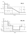
- FIG. 3 is a diagram showing another embodiment of an optical fiber profile that compensates for bend losses, where ⁇ n ped ⁇ n BCin and ⁇ n out ⁇ n BCout .
- FIG. 4A is a diagram showing another embodiment of an optical fiber profile that compensates for bend losses, where ⁇ n BCin ⁇ n BCout ⁇ n trench .
- FIG. 4B is a table showing example values for the optical fiber profile of FIG. 4A .
- FIGS. 5A, 5B, and 5C are charts showing loss (in dB/m) as a function of bend diameter (in mm).
- Bending of optical fibers affects signals that propagate through the optical fibers.
- Previous works have explored bend compensation for optical fibers that have known curvatures, such as for optical fibers that are used in fiber amplifier applications. For those types of applications, a large portion of the optical fiber is typically coiled to a fairly well-defined bend radius. Consequently, a manufacturer can compensate for that known bend at the time of fiber fabrication. Thus, when the optical fiber is eventually coiled, the bend in the fiber has already been taken into consideration to mitigate the effects of the bend.
- the various embodiments disclosed herein overcome this difficulty by, first, managing fiber bends so that single-modedness need not be achieved in a straight arrangement, and, second, applying a bend-compensated strategy, where the perturbation induced by the managed “cable” bend is pre-compensated.
- Bend management can be achieved through known cabling techniques (e.g., by controlling the approximately-helical shape of the fiber within the cable), and can greatly relax the single-modedness requirement (allowing the higher index contrast).
- the bend-compensated fiber index profile allows one to achieve greater bend insensitivity.
- the optical fiber meets two bend-loss conditions, namely, a tight macro-bend loss condition (or, simply, tight bend condition) and a cabling macro-bend loss condition (or, simply, cable bend condition).
- the optical fiber comprises an effective area that is less than approximately 300 ⁇ m 2 with a tight bend condition of approximately one (1) decibel (dB) per meter (m) at a tight-bend diameter (D bend,t ) of approximately twenty (20) millimeters (mm) and a cable bend condition of approximately 10 ⁇ 5 dB/m at a cable bend diameter (D bend,c ), where D bend,c is defined to be two (2) times the radius of curvature of the bend of the optical fiber as it is arranged in the cable.
- dB decibel
- D bend,t tight-bend diameter
- mm millimeters
- LMA large-mode-area
- FIG. 1 is a diagram showing one embodiment of an optical fiber profile that compensates for bend losses.
- the optical fiber profile comprises a core that has a core index (n core ) and extends to a core radius (R core ).
- index values are provided relative to pure silica at 633 nanometers (nm), which is the wavelength often used for measuring index profiles.
- n core n silica + ⁇ n core
- n BCin n silica + ⁇ n BCin ; etc.
- radially exterior to the core is a pedestal region that has a pedestal index (n ped ) and extends to a pedestal radius (R ped ).
- Radially exterior to the pedestal region is a bend compensation (BC) region, which extends from an inner radius (R BCin ) to an outer radius (R BCout ).
- the BC region is graded or stepped such that the index at R BCin (n BCin ) is greater than the index at R BCout (n BCout ).
- n ped ⁇ n BCin In order to properly compensate for a bend radius (R bend ), such that: ⁇ ( n BCout ⁇ n BCin )/( R BCout ⁇ R BCin ) ⁇ 0.8( n silica /R bend ) [Eq. 1].
- R bend a bend radius
- n ped ⁇ n BCin In order to properly compensate for a bend radius (R bend ), such that: ⁇ ( n BCout ⁇ n BCin )/( R BCout ⁇ R BCin ) ⁇ 0.8( n silica /R bend ) [Eq. 1].
- R bend a bend radius
- FIG. 3 is a diagram showing the embodiment of the optical fiber profile, where ⁇ n ped ⁇ n BCin and ⁇ n out ⁇ n BCout .
- a mode area of an optical fiber is primarily determined by its core radius R core .
- R core a larger radius translates into a larger mode area.
- HOM higher-order modes
- n core and n out be large enough to satisfy fabrication constraints, such as, for example, the outer cladding being made of low-cost materials while the core has sufficient dopant concentration to reduce the impact of manufacturing variability, or sufficient Ytterbium (Yb) and aluminum (Al) to achieve high gain and low photo-darkening.
- these constraints translate to (n core ⁇ n out ) being greater than approximately 10 ⁇ 3 .
- R BCin since R BCin has an impact on both HOM suppression and fundamental-mode bend-loss, it is preferable to maintain a proper ratio of R BCin to R core (R BCin /R core ).
- FIGS. 2B, 2C, and 2D are tables showing specific dimensional values (R) and relative index values ( ⁇ n) for the optical fiber profile of FIG. 2A . Further shown in FIGS. 2B, 2C, and 2D are the effective areas and losses that correspond to the R and ⁇ n.
- FIG. 2B shows optical fiber profiles having R core between approximately 9 ⁇ m and 12 ⁇ m, R BCin between approximately 24 ⁇ m and 36 ⁇ m, which translates into a R BCin /R core that ranges between approximately 2.5 and 3.
- the cable bend had an equivalent bend diameter of 30 mm
- the tight-bend is a macro-bending loss that is less than 10 dB/m at D bend,t of 20 mm at a wavelength of 1550 nm.
- the n core ⁇ n ped preferably ranges between approximately 3.5 ⁇ 10 ⁇ 3 and 4 ⁇ 10 ⁇ 3 .
- FIG. 2C shows values for index profiles where resistance to very tight bends may be desirable.
- FIG. 2C shows target values for a cable bend with an equivalent bend diameter of 25 mm, where the tight-bend is a macro-bending loss that is less than 10 dB/m at D bend,t of 15 mm at a wavelength of 1550 nm. This implies a loss of approximately 0.5 dB for a single turn.
- the BC ratio is approximately 1, with R BCin /R core being approximately 3.
- Calculated micro-bend sensitivity shows that it increases (in arbitrary units) as a function of increasing A eff .
- fibers that are suitable for tighter bends will generally have a larger n core ⁇ n BCin and a larger gradient (in proportion to 1/R bend,t so that the bend compensation ration stays at approximately 1.
- These optical fiber profiles having large A eff (between approximately 120 ⁇ m 2 and 160 ⁇ m 2 ), large HOM loss and negligible tunneling loss at a D bend,c that is less than approximately 18 mm, and a 3 dB/m loss at D bend,t of approximately 10 mm.
- the fiber profiles have BC ratios that range between approximately 0.9 and 1.2, maintain moderate micro-bending sensitivity, and an outer diameter of approximately 125 ⁇ m (twice the value of R BCout ).
- FIG. 4A is a diagram showing another embodiment of an optical fiber profile that compensates for bend losses, where ⁇ n BCin ⁇ n BCout ⁇ n trench
- the difference between FIG. 2A and FIG. 4A is that the gradient in the BC region is flat for FIG. 4A while it is graded for FIG. 2A . Consequently, FIG. 4A shows a single-step BC region.
- R ped /R core ranges between approximately 3.5 and 4
- n core ⁇ n ped ranges between approximately 3.5 ⁇ 10 ⁇ 3 and 4.5 ⁇ 10 ⁇ 3
- n trench ⁇ n ped ranges between approximately ⁇ 2 ⁇ 10 ⁇ 3 and ⁇ 1 ⁇ 10 ⁇ 3 .
- the various embodiments show optical fibers having A eff less than approximately 350 ⁇ m 2 , a tight bend loss less than approximately 5 dB/m at a minimum D bend,t less than approximately 20 mm, and a cable bend loss less than approximately 10 ⁇ 5 dB/m at a minimum D bend,c less than approximately 50 mm.
- a general index profile of such fibers include a core (with n core and R core ), a pedestal region surrounding the core (with n ped ⁇ n core ), which has a radius (R BCin ) such that R BCin /R core is between approximately 2.5 and 4.5.
- a bend compensation (BC) region (extending from R BCin to R BCout , and having an indices of refraction n BCin ⁇ n core and n BCout ⁇ n core ).
- BCin ⁇ n ped Radially surrounding the pedestal region is a bend compensation (BC) region (extending from R BCin to R BCout , and having an indices of refraction n BCin ⁇ n core and n BCout ⁇ n core ).
- n BCin ⁇ n ped n BCout ⁇ n BCin .
- R core ranges from approximately 7 ⁇ m to 14 ⁇ m, with A eff being between approximately 110 ⁇ m 2 and 300 ⁇ m 2 .
- R BCin ranges from approximately 24 ⁇ m to 52 ⁇ m, and R BCout ranges from approximately 50 ⁇ m to 70 ⁇ m.
- D bend,t are as small as approximately 10 mm for some embodiments, and D bend,c for some embodiments are less than approximately 35 mm. It should be appreciated that the particular dimensions can vary based on design criteria, as long as both tight bend and cable bend conditions are met.
- FIGS. 5A, 5B, and 5C are charts showing loss (in dB/m) as a function of bend diameter (in mm).
- the solid line shows fundamental-mode loss as a function of bend diameter.
- bend-loss specifications for fiber-optic cables address the fundamental-mode loss (solid line).
- the broken line shows higher-order mode (HOM) loss as a function of bend diameter. This HOM loss determines the single-modedness of the fiber.
- FIG. 5A shows the bend-loss plot for an optical fiber having an effective area (A eff ) of approximately 170 ⁇ m;
- the HOM loss is very small and, thus, the optical fiber does not exhibit the desired single-modedness at this bend diameter.
- FIGS. 5B and 5C provide examples of how a non-standard cable cutoff permits relaxation of the single-modedness condition, thereby permitting the design of optical fibers that balance the tradeoff between mode area, bend loss, and single-modedness for different bend conditions. Consequently, the optical fiber has a HOM loss at D bend,c such that the optical fiber exhibits single-moded behavior at D bend,c .
- optical fiber profiles are shown in which the optical fiber has a large mode area, but is nevertheless sufficiently bend-insensitivity to comply with technical specifications for telecommunication optical fibers.
- the optical fibers meet two bend-loss conditions. First, they meet tight bend conditions, which reflects macro-bending due to coiling or bending of the optical fiber. Second, these optical fibers meet cable bend conditions, which reflect macro-bending conditions that are introduced as a result of cabling. By satisfying the tight bend-loss condition and then adjusting for the cable bend-loss condition, the optical fiber permits larger effective areas than normally achievable with conventional designs. Unlike previous bend-compensated designs, the designs disclosed here show how bend compensation can be applied to satisfy simultaneous tight-bend and cable-bend requirements.
Landscapes
- Physics & Mathematics (AREA)
- General Physics & Mathematics (AREA)
- Optics & Photonics (AREA)
- Light Guides In General And Applications Therefor (AREA)
Abstract
Description
−(n BCout −n BCin)/(R BCout −R BCin)≈0.8(n silica /R bend) [Eq. 1].
For the particular embodiment of
BC ratio=0.8n silica(R BCout −R BCin)/[(D bend,c/2)*(D NBCin −DN BCout)]
Claims (13)
Priority Applications (1)
| Application Number | Priority Date | Filing Date | Title |
|---|---|---|---|
| US14/302,963 US9459402B2 (en) | 2014-06-12 | 2014-06-12 | Bend compensation in telecommunications optical fibers |
Applications Claiming Priority (1)
| Application Number | Priority Date | Filing Date | Title |
|---|---|---|---|
| US14/302,963 US9459402B2 (en) | 2014-06-12 | 2014-06-12 | Bend compensation in telecommunications optical fibers |
Publications (2)
| Publication Number | Publication Date |
|---|---|
| US20150362670A1 US20150362670A1 (en) | 2015-12-17 |
| US9459402B2 true US9459402B2 (en) | 2016-10-04 |
Family
ID=54836006
Family Applications (1)
| Application Number | Title | Priority Date | Filing Date |
|---|---|---|---|
| US14/302,963 Active 2035-01-02 US9459402B2 (en) | 2014-06-12 | 2014-06-12 | Bend compensation in telecommunications optical fibers |
Country Status (1)
| Country | Link |
|---|---|
| US (1) | US9459402B2 (en) |
Families Citing this family (1)
| Publication number | Priority date | Publication date | Assignee | Title |
|---|---|---|---|---|
| CN113985520A (en) * | 2021-11-11 | 2022-01-28 | 桂林电子科技大学 | Large-mode-field single-mode transmission optical fiber |
Citations (1)
| Publication number | Priority date | Publication date | Assignee | Title |
|---|---|---|---|---|
| US20090060437A1 (en) * | 2007-06-15 | 2009-03-05 | John Michael Fini | Bend insensitivity in single mode optical fibers |
-
2014
- 2014-06-12 US US14/302,963 patent/US9459402B2/en active Active
Patent Citations (1)
| Publication number | Priority date | Publication date | Assignee | Title |
|---|---|---|---|---|
| US20090060437A1 (en) * | 2007-06-15 | 2009-03-05 | John Michael Fini | Bend insensitivity in single mode optical fibers |
Also Published As
| Publication number | Publication date |
|---|---|
| US20150362670A1 (en) | 2015-12-17 |
Similar Documents
| Publication | Publication Date | Title |
|---|---|---|
| CN101883998B (en) | Bend insensitivity in single mode optical fibers | |
| US7257293B1 (en) | Fiber structure with improved bend resistance | |
| JP6486533B2 (en) | Optical fiber | |
| EP2984509B1 (en) | Low bend loss optical fiber | |
| US11314017B2 (en) | Optical fiber | |
| JP2012203416A (en) | Multimode optical fiber with improved bend resistance | |
| JP5222752B2 (en) | Optical fiber | |
| EP2003476A1 (en) | Bend insensitivity in single mode optical fibers | |
| WO2020162406A1 (en) | Optical fiber | |
| US10222545B2 (en) | Optical fiber | |
| WO2016017743A1 (en) | Optical fiber and method for producing same | |
| KR102776021B1 (en) | Optical Fiber | |
| CN111399113B (en) | Small-outer-diameter bending insensitive single-mode optical fiber | |
| WO2012128250A1 (en) | Optical fiber, optical fiber cord, and optical fiber cable | |
| CN105408784B (en) | Bending-resistant multimode optical fiber with reduced leaky mode effects | |
| CN116256837B (en) | A high-bandwidth bend-insensitive multimode optical fiber | |
| US9459402B2 (en) | Bend compensation in telecommunications optical fibers | |
| CN114641714A (en) | Optical fiber | |
| CN111527430B (en) | optical fiber | |
| CN110824610B (en) | Bending insensitive single mode fiber | |
| US11714228B2 (en) | Optical fiber and method of manufacturing optical fiber | |
| JP5118900B2 (en) | Plastic glass optical fiber | |
| KR20110112681A (en) | Optical fiber with extremely low bending loss | |
| JP2014523001A (en) | Nonlinear fiber resistant to perturbation | |
| US20160216439A1 (en) | Multimode optical fiber |
Legal Events
| Date | Code | Title | Description |
|---|---|---|---|
| AS | Assignment |
Owner name: OFS FITEL, LLC, GEORGIA Free format text: ASSIGNMENT OF ASSIGNORS INTEREST;ASSIGNOR:FINI, JOHN M;REEL/FRAME:033090/0714 Effective date: 20140529 |
|
| STCF | Information on status: patent grant |
Free format text: PATENTED CASE |
|
| FEPP | Fee payment procedure |
Free format text: SURCHARGE FOR LATE PAYMENT, LARGE ENTITY (ORIGINAL EVENT CODE: M1554); ENTITY STATUS OF PATENT OWNER: LARGE ENTITY |
|
| MAFP | Maintenance fee payment |
Free format text: PAYMENT OF MAINTENANCE FEE, 4TH YEAR, LARGE ENTITY (ORIGINAL EVENT CODE: M1551); ENTITY STATUS OF PATENT OWNER: LARGE ENTITY Year of fee payment: 4 |
|
| FEPP | Fee payment procedure |
Free format text: 7.5 YR SURCHARGE - LATE PMT W/IN 6 MO, LARGE ENTITY (ORIGINAL EVENT CODE: M1555); ENTITY STATUS OF PATENT OWNER: LARGE ENTITY |
|
| MAFP | Maintenance fee payment |
Free format text: PAYMENT OF MAINTENANCE FEE, 8TH YEAR, LARGE ENTITY (ORIGINAL EVENT CODE: M1552); ENTITY STATUS OF PATENT OWNER: LARGE ENTITY Year of fee payment: 8 |