US9459174B1 - Bellows leakage tester and methods for testing bellows - Google Patents
Bellows leakage tester and methods for testing bellows Download PDFInfo
- Publication number
- US9459174B1 US9459174B1 US14/145,200 US201314145200A US9459174B1 US 9459174 B1 US9459174 B1 US 9459174B1 US 201314145200 A US201314145200 A US 201314145200A US 9459174 B1 US9459174 B1 US 9459174B1
- Authority
- US
- United States
- Prior art keywords
- bellows
- shaft
- base
- opening
- ring seal
- Prior art date
- Legal status (The legal status is an assumption and is not a legal conclusion. Google has not performed a legal analysis and makes no representation as to the accuracy of the status listed.)
- Expired - Fee Related, expires
Links
Images


Classifications
-
- G—PHYSICS
- G01—MEASURING; TESTING
- G01M—TESTING STATIC OR DYNAMIC BALANCE OF MACHINES OR STRUCTURES; TESTING OF STRUCTURES OR APPARATUS, NOT OTHERWISE PROVIDED FOR
- G01M3/00—Investigating fluid-tightness of structures
- G01M3/02—Investigating fluid-tightness of structures by using fluid or vacuum
- G01M3/027—Details with respect to the testing of elastic elements, e.g. gloves, condoms
-
- G—PHYSICS
- G01—MEASURING; TESTING
- G01M—TESTING STATIC OR DYNAMIC BALANCE OF MACHINES OR STRUCTURES; TESTING OF STRUCTURES OR APPARATUS, NOT OTHERWISE PROVIDED FOR
- G01M3/00—Investigating fluid-tightness of structures
- G01M3/02—Investigating fluid-tightness of structures by using fluid or vacuum
- G01M3/26—Investigating fluid-tightness of structures by using fluid or vacuum by measuring rate of loss or gain of fluid, e.g. by pressure-responsive devices, by flow detectors
- G01M3/28—Investigating fluid-tightness of structures by using fluid or vacuum by measuring rate of loss or gain of fluid, e.g. by pressure-responsive devices, by flow detectors for pipes, cables or tubes; for pipe joints or seals; for valves ; for welds
- G01M3/2846—Investigating fluid-tightness of structures by using fluid or vacuum by measuring rate of loss or gain of fluid, e.g. by pressure-responsive devices, by flow detectors for pipes, cables or tubes; for pipe joints or seals; for valves ; for welds for tubes
Definitions
- aspects of the present invention relate to a bellows of a gate valve assembly for a sputtering machine, and more specifically to leakage testing of a bellows of the gate valve assembly.
- a bellows 1004 is a component used in a gate valve (GV) assembly 1002 of a sputtering machine 1000 (see FIGS. 10 a , 10 b , 10 c ).
- GV gate valve
- the sputtering machine is often used in the manufacturing of media disks used for magnetic recording.
- the sputtering machine may have a number of process chambers (e.g., about twenty to twenty-four chambers) where carrier holders (for holding disks or substrates) are transferred from one chamber to another chamber to enable the disks to be sputtered.
- Each carrier holder will go in and out of each chamber and generally stop for a few seconds in each chamber during the process flow to complete one cycle.
- the GV assemblies close both ends of the chamber.
- the environment inside the chamber may be kept in a vacuum condition which allows the sputtering process to begin.
- the GV assembly is used to provide separation between adjacent process chambers of a sputtering machine to ensure that the respective sputtering processes for each individual chamber remain separate. This is achieved when the GV assembly extends its actuator shaft to close the opening between the chambers and compress the bellows.
- the bellows is an elastic component (e.g., an elastic metallic vessel) that can be compressed or extended under vacuum pressure. When the vacuum pressure is released, the compressed bellows will return to its original uncompressed shape. In the sputtering machine, the bellows protects the inside environment of the process chamber from being exposed to the outside environment (e.g., atmosphere environment). If the bellows is found to have a leak, the bellows needs to be replaced. However, detecting a leak in the bellows of a sputter machine can involve complicated and time consuming test processes.
- FIG. 1 is a schematic perspective view of a bellows leakage tester and a bellows cover in accordance with one embodiment of the invention.
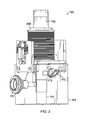
- FIG. 2 is a schematic perspective view of a bellows leakage tester and a bellows under test in a static mode test in accordance with one embodiment of the invention.
- FIG. 3 is a schematic side cross sectional view of a bellows leakage tester and a bellows under test in the static mode test in accordance with one embodiment of the invention.
- FIG. 4 is a schematic side cross sectional view of a bellows leakage tester and a bellows under test in the static mode using a bellows cover in accordance with one embodiment of the invention.
- FIG. 5 is a flowchart illustrating a process for performing a static mode test for testing a bellows in accordance with an embodiment of the invention.
- FIG. 6 is a schematic perspective view of a bellows leakage tester and a bellows under test in a compressed mode test in accordance with one embodiment of the invention.
- FIG. 7 is a flowchart illustrating a process for performing a compress mode test for testing a bellows in accordance with one embodiment of the invention.
- FIG. 8 is a flowchart illustrating a method for testing for air leakage of a bellows in accordance with an embodiment of the invention.
- FIG. 9 is a flowchart illustrating a method for testing for air leakage of a bellows in accordance with an embodiment of the invention.
- FIG. 10 a is a schematic perspective view of a process chamber of a sputtering machine including a gate valve (GV) assembly.
- GV gate valve
- FIG. 10 b is a schematic perspective view of the GV assembly of FIG. 10 a with a bellows.
- FIG. 10 c is a schematic perspective view of the bellows of FIG. 10 b.
- Various embodiments of the present invention are directed to an apparatus and methods for testing a bellows for leakage. Therefore, the condition of a bellows can be determined before installing the bellows within a gate valve (GV) assembly of a sputtering machine and also after removing the bellows from the GV assembly.
- GV gate valve
- a bellows is considered to be in a substantially perfect working condition when no effective leakage can be detected when the bellows is in a compressed or an uncompressed position.
- a bellows leakage tester configured to determine a bellows' condition (leaking or not leaking) and identify the leakage location of the bellows if the bellows is leaking.
- the bellows leakage tester can be operated in at least two test modes including a static mode and a compressed mode. In the static test mode, the bellows is tested in an uncompressed position. In the compressed test mode, the bellows is tested in a compressed position. Examples for using the bellows leakage tester in the static test mode and the compressed test mode will be described in detail below.
- FIG. 1 is a schematic perspective view of a leakage tester 100 for a bellows and a bellows cover 100 in accordance with one embodiment of the invention.
- the leakage tester 100 has a base 101 , and a shaft (e.g., a modified actuator shaft) 102 that extends from a top side of the base 101 in a vertical direction (the axial direction of the shaft 102 ).
- a shaft e.g., a modified actuator shaft
- Two side plates 104 extend from opposite sides of the base 101 in the vertical direction.
- the side plates 104 may be secured to the base 101 by any suitable fasteners such as bolts, screws, studs, retaining pins, rivets, etc.
- the side plates 104 may be an integral part of the base 101 or welded to the base 101 .
- a top compression plate 106 is placed on the side plates 104 in a substantially horizontally position.
- the top compression plate 106 can be removably secured to the side plates 104 . Therefore, the side plates 104 extend from the top side of the base 101 to the top compression plate 106 .
- the top compression plate 106 may be secured to the side plates 104 with a hook and latch mechanism 108 .
- a retaining shaft 110 is provided for retaining the actuator shaft 102 , for example, in one of at least two selectable positions (e.g., openings) along the vertical axis of a bottom portion of the actuator shaft 102 .
- the retaining shaft 110 can be inserted through a hole of the base 101 and extended to one of the at least two selectable positions/openings on the bottom portion of the actuator shaft 102 .
- An air outlet or exhaust 112 is located on a side of the base 101 , which will be described in more detail below. It should be appreciated that the relative positions (e.g., top, bottom, left, right, front, and back, etc.) of the described features of the leakage tester 100 are not limiting in nature, but chosen for the ease of reference.
- the leakage tester 100 may be used to test a bellows for leakage in the static mode in which is the bellows is positioned in a way similar that of a GV assembly in a refracted position. In this case, the bellows is not compressed.
- FIG. 2 is a schematic perspective view of the leakage tester 100 configured for testing a bellows 200 in a static mode test in accordance with one embodiment of the invention.
- a process for testing a bellows 200 in the static mode will be described in detail below in reference to FIGS. 3 and 4 .
- the process can place the bellows 200 under test in effectively the same uncompressed position as it exists in a GV assembly when the shaft is retracted with no applied pressure.
- a technician operating the bellows leakage tester 100 will be able to determine the leakage location, if any, on the bellows 200 .
- the leakage location may be on the O-ring sealing area or on the bellows pitch of the bellows 200 .
- FIG. 3 is a schematic side cross sectional view of the leakage tester 100 for testing the bellows 200 in the static mode test in accordance with one embodiment of the invention.
- the bellows 200 has a cylindrical shape with a first opening (e.g., top opening) 204 and a second opening (e.g., bottom opening) 206 positioned at opposite ends of the bellows.
- the bellows 200 further includes a first O-ring seal (e.g., top O-ring seal) 208 proximate the first opening 204 and configured to make an airtight seal between the bellows 200 and the shaft 102 .
- a first O-ring seal e.g., top O-ring seal
- the bellows also includes a second O-ring seal (e.g., bottom O-ring seal) 214 proximate the second opening 206 and configured to make an airtight seal between the bellows 200 and a top surface of the base 101 .
- the body of the bellows 200 has a pitch area 209 that has a suitable flexibility such that the bellows 200 may be compressed or uncompressed (expand) under a vacuum pressure in at least one direction (e.g., an axial direction).
- the shaft 102 is configured to receive the bellows 200 in an axial direction (e.g., vertical direction in the figure) of the shaft 102 . More specifically, the shaft 102 passes through the first/top opening 204 and the second/bottom opening 206 .
- the shaft 102 extends upward from the top surface of the base 101 and holds the bellows 200 in a vertical position such that the shaft 102 and the bellows 200 are substantially concentrically arranged.
- the shaft 102 has a portion configured to engage the first O-ring seal 208 that is proximate or close to the first opening 204 of the bellows.
- FIG. 4 is a schematic side cross sectional view of the leakage tester 100 for testing a bellows in the static mode under a vacuum condition using a bellows cover 120 installed in accordance with an embodiment of the invention.
- the leakage tester 100 shown in FIG. 4 is substantially the same as the one shown in FIG. 3 except the addition of the bellows cover 120 .
- the bellows cover 120 functions as a shield to make sure the whole bellows body is in vacuum condition.
- the bellows cover 120 encloses, in conjunction with the top side of the base 101 , the pitch area 209 of the bellows while purposely not enclosing the O-ring seals 208 and 214 of the bellows.
- the bellows cover 120 acts as an airtight barrier for the enclosed pitch area 209 and has seals 402 located at top and bottom ends for providing airtight sealing at both ends of the bellows 200 . Therefore, the bellows pitch area 209 itself can be kept in a vacuum condition to facilitate the detection of a leak in any of the O-ring seals 208 and 214 . In this configuration, any leakage, if detected, will have been caused by a leaky O-ring seal. As shown in FIG. 4 , the bellows cover 120 , the bellows 200 , and the shaft 102 are concentrically arranged with the shaft positioned substantially at the center of the bellows.
- a bellows leakage test in the static mode can be performed in using a bellows leakage tester (e.g., such as those depicted in FIGS. 1 to 4 ) and the testing processes as described below.
- a bellows leakage tester e.g., such as those depicted in FIGS. 1 to 4
- the testing processes as described below.
- FIG. 5 is a flowchart illustrating a static mode test for testing a bellows in accordance with an embodiment of the present invention.
- the position of the shaft 102 of the leakage tester 100 is adjusted vertically (axial direction), if needed, and secured at a higher position relative to the base 101 of the tester.
- the base 101 has an opening 114 on the top side for receiving an end portion of the shaft 102 in the axial direction.
- the higher position allows the bellows 200 to be tested in a static mode (uncompressed).
- This position can be fixed by inserting the retaining shaft 110 (see FIG. 2 ) through a hole 113 (see FIG. 2 ) of the base 101 and then into a lower hole 310 (see FIG. 3 ) of two or more holes in the end portion of shaft 102 .
- the bellows 200 is placed over the middle portion of the shaft 102 in the axial direction and fastened to the top side of the base 101 using, for example, one or more screws 312 (e.g., four cap M6 type screws).
- the screws 312 go into respective holes located at the corners of the bellows 200 .
- other types of fasteners may be used.
- the O-ring seal 208 e.g., a vacuum seal gland
- positioned near the bellows' top end/opening 204 should be seated properly (e.g., perfectly fit) onto the shaft 102 (see FIG. 3 ).
- the O-ring seal 208 can provide an airtight seal between the top opening 204 of the bellows and the shaft 102 , provided that the seal is not defective.
- the top side of the base 101 engages a second O-ring seal 214 that is proximate or close to the bottom opening 206 of the bellows.
- the second O-ring seal 214 facilitates an airtight seal between a bottom surface of the bellows 200 and the top side of the base 101 such that an airtight space 216 is formed inside the bellows 200 between the top (first) O-ring seal 208 and the bottom (second) O-ring seal 214 .
- a volume of the airtight space 216 may be changed by moving the shaft 102 in the axial direction. For example, moving the shaft 102 up will increase the volume of the airtight space 216 , but moving the shaft 102 down will decrease the volume.
- the air exhaust 112 of the bellows tester 100 is coupled to a suitable air leakage detector 130 (see FIG. 3 ) that can apply a suitable vacuum pressure (e.g., constant vacuum pressure) to the airtight space 216 .
- the air leakage detector 130 can be any air leakage detector or the like, including those that are well known in the industry.
- An air conduit 113 extends from the air exhaust 112 through the base 101 and to the airtight space 216 , and effectively forms a part of an airtight connection between the airtight space 216 and the air leakage detector 130 .
- an identifiable gas such as helium (He) may be sprayed in the area proximate the bellows (e.g., particularly near the O-ring seal areas) when the air leakage detector 130 applies a vacuum pressure to the airtight space 216 via the air conduit 113 .
- the identifiable gas is used as a marker to assist in leakage detection.
- suitable identifiable gases other than He may be used as the marker.
- the bellows cover 120 functions as a shield to make sure the whole bellows body is in vacuum condition.
- the bellows cover 120 encloses, in conjunction with the top side of the base 101 , the pitch area 209 of the bellows while not enclosing the O-ring seals 208 and 214 .
- the bellows cover 120 acts as an airtight barrier for the enclosed pitch area and has seals 402 located at top and bottom ends for providing airtight sealing at both ends of the bellows 200 . Therefore, the bellows pitch 209 itself can be kept in a vacuum condition to facilitate the detection of a leak in any of the O-ring seals 208 and 214 .
- any leakage, if detected, will have been caused by a leaky O-ring seal.
- the bellows cover 120 , the bellows 200 , and the shaft 102 are concentrically arranged with the shaft positioned substantially at the center of the bellows.
- the air leakage detector is operated to apply a vacuum pressure to the bellows 200 through the air exhaust 112 , while an identifiable gas (e.g., helium) is sprayed near the O-ring sealing area. If no air leakage is detected by the air leakage detector, it can be concluded that the previously detected air leakage (without using the bellows cover 120 ) is caused by a leak on the bellows pitch 209 . As such, the defective bellows can be scrapped and replaced with a new bellows. However, if a leak is detected, it indicates that the air leakage has occurred at one of the O-ring sealing areas.
- an identifiable gas e.g., helium
- new O-ring seals may be installed to replace the old O-ring seals 208 and 214 . Then, the testing procedures of blocks A 1 to A 3 are repeated. If no air leakage is detected in the static mode test, the bellows 200 will be tested for air leakage in a compress mode test to be described in detail below.
- FIG. 6 is a schematic perspective view of the leakage tester 100 configured for testing the bellows 200 in a compressed mode test in accordance with one embodiment of the invention.
- FIG. 7 is a flowchart illustrating a compress mode test for testing a bellows in accordance with one embodiment of the invention.
- the bellows 200 is already installed on the leakage tester 100 as illustrated in FIG. 3 .
- the retaining shaft 110 is inserted into an upper hole 511 (see FIG. 6 ) on the shaft 102 through a hole of the base 101 .
- the retaining shaft 110 may be relocated to the upper hole 311 from the lower hole 310 , which was used in the static mode test described above. By performing this procedure, the height of the shaft 102 is decreased (lowered) relative to that of the static mode test.
- the upper hole 311 is aligned with the hole 113 of the base 101 such that the holes are substantially aligned (e.g., concentric) with each other. Then, the retaining shaft 110 can be inserted into both holes to secure the axial position (e.g., vertical position) of the shaft 102 . At this time, the bellows 200 can be pressed down (compressed) as well to its compressed position.
- a top compression plate 106 is installed on the bellows 200 to apply a compressive force to the bellows 200 in the axial direction.
- the compression plate 106 and the top side of the base 101 are respectively in contact with the opposite ends of the bellows 200 , and retain the bellows in the compressed position by applying compressive forces to the bellows in the axial direction (vertical direction in FIG. 6 ).
- the top compression plate 106 has a hole suitably sized such that the shaft 102 can extend therethrough until the bottom of the top compression plate 106 touches or contacts the bellows' top surface.
- the top compression plate 106 may be removably secured to the side plates 104 with any suitable fasteners such as a hook and latch mechanism 108 shown in the figures. Respective parts of the hook and latch mechanism 108 may be attached to the side plate 104 and top compression plate 106 by any suitable methods. In some embodiments, the hook and latch mechanism 108 may be secured by fasteners such as bolts, screws, studs, retaining pins, rivets, etc. In other embodiments, the hook and latch mechanism 108 may be secured by welding or adhesive.
- the bellows 200 is secured in the compressed position by fastening the top compression plate 106 to the side plates 104 extending from the base 101 .
- the latch mechanism 108 may include spring latches (or other suitable fasteners such as quick release fasteners) installed on the respective side plates 104 , and the spring latches are configured to engage respective hooks positioned on opposite edges of the top compression plate 106 . Once the hooks and latches are in a locked position, the bellows 200 is secured in the compressed position.
- an air leakage test similar to the test described in blocks A 1 through A 3 of FIG. 5 is performed to check for air leakage on the bellows 200 . If no leakage is found, then the bellows 200 is in satisfactory working condition for general use and may be installed in the GV assembly in block B 5 . However, if an air leakage is detected, then the bellows 200 is defective and will be scrapped in block B 6 . In such case, an operator can replace the defective bellows with a new bellows and repeat the static mode test and compress mode test as described above to test the new bellows.
- the above described embodiments of the offline leakage tester 100 can test a bellows offline to determine its condition before the bellows is installed in a GV assembly. Therefore, the offline leakage tester and testing methods of the present invention can save valuable time currently spent on determining the condition of the bellows after it has already been installed in a GV assembly. More specifically, the offline bellows tester 100 can identify the leaky location (e.g., pitch area or O-ring seal) on the bellows.
- the leaky location e.g., pitch area or O-ring seal
- FIG. 8 is a flowchart illustrating a method for testing air leakage of a bellows in accordance with an embodiment.
- the method may be performed using the leakage tester 100 to test a bellows 200 .
- the method of FIG. 8 can incorporate elements of both the static mode test and the compress mode test.
- the bellows 200 is retained in the bellows leakage tester 100 in an uncompressed position (e.g., FIGS. 3 and 4 ) and a compressed position (e.g., FIG. 6 ).
- the bellows includes a first opening and a second opening. The first and second openings are located at opposite ends of the bellows.
- the bellows further includes a first O-ring seal 208 proximate the first opening and a second O-ring seal 214 proximate the second opening.
- an airtight space 216 is formed inside the bellows between the first O-ring seal and the second O-ring seal of the bellows.
- a vacuum pressure is applied to the airtight space via the bellows leakage tester.
- the bellows is tested for any air leakage in the compressed position and the uncompressed position.
- the testing procedures illustrated in FIG. 5 may be used to test the bellows in the uncompressed position, and the testing procedures illustrated in FIG. 7 may be used to test the bellows in the compressed position.
- FIG. 9 is a flowchart illustrating a method for testing air leakage of a bellows in accordance with an embodiment.
- the method may be performed using the bellows leakage tester 100 to test a bellows 200 .
- the method of FIG. 9 is slightly more focused on elements of the static mode test (e.g., the uncompressed position).
- the method of FIG. 9 can incorporate elements of both the static mode test and the compress mode test.
- the bellows 200 is secured in the bellows leakage tester 100 .
- the bellows includes a first opening and a second opening.
- the first and second openings are positioned at opposite ends of the bellows.
- the bellows further includes a first O-ring seal 208 proximate the first opening and a second O-ring seal 214 proximate the second opening.
- an airtight space is formed inside the bellows between the first O-ring seal and the second O-ring seal of the bellows.
- the bellows 200 is tested for air leakage with the bellows in an uncompressed position (e.g., FIGS. 3 and 4 ). With the bellows in the uncompressed position, in block D 4 , a first leakage test is performed for detecting air leakage of the bellows through a pitch area, the first O-ring seal, or the second O-ring seal.
- the first leakage test may be performed according to the testing procedures described in blocks A 1 , A 2 , A 3 , and A 4 of FIG. 5 . If air leakage is detected in the first leakage test, a second leakage test is performed for detecting air leakage of the bellows through the first O-ring seal or the second O-ring seal, excluding the pitch area. In one embodiment, the second leakage test may be performed according to the testing procedures described in blocks A 1 , A 2 , A 3 and A 4 of FIG. 5 . In some embodiments, if no air leakage of the bellows is detected with the first and second leakage tests, the bellows can be compressed and a third leakage test is performed for testing for air leakage of the bellows. In such case, the third leakage test can be performed according to the testing procedures described in FIG. 7 .
- the processes of FIGS. 5, 7, 8, and 9 can perform the sequence of actions in a different order. In another embodiment, the processes can skip one or more of the actions. In other embodiments, one or more of the actions are performed simultaneously. In some embodiments, additional actions can be performed.
- FIG. 10 a is a schematic perspective view of a process chamber 1000 of a sputtering machine including a GV assembly 1002 .
- FIG. 10 b is a schematic perspective view of the GV assembly 1002 including a bellows 1004 .
- FIG. 10 c is a schematic perspective view of the bellows 1004 illustrated in more detail.
- the bellows 1004 may be the same as the bellows 200 and may be tested for leakage using the leakage tester 100 .
- the bellows 1004 may be an elastic metallic vessel that can be compressed when a compressive force (pressure) is applied in the axial direction of the bellows, or extended under a vacuum pressure. When the pressure is released, the bellows will return to its original shape.
- pressure compressive force
Landscapes
- Physics & Mathematics (AREA)
- General Physics & Mathematics (AREA)
- Examining Or Testing Airtightness (AREA)
Abstract
Description
Claims (8)
Priority Applications (1)
| Application Number | Priority Date | Filing Date | Title |
|---|---|---|---|
| US14/145,200 US9459174B1 (en) | 2013-09-18 | 2013-12-31 | Bellows leakage tester and methods for testing bellows |
Applications Claiming Priority (2)
| Application Number | Priority Date | Filing Date | Title |
|---|---|---|---|
| US201361879235P | 2013-09-18 | 2013-09-18 | |
| US14/145,200 US9459174B1 (en) | 2013-09-18 | 2013-12-31 | Bellows leakage tester and methods for testing bellows |
Publications (1)
| Publication Number | Publication Date |
|---|---|
| US9459174B1 true US9459174B1 (en) | 2016-10-04 |
Family
ID=56995266
Family Applications (1)
| Application Number | Title | Priority Date | Filing Date |
|---|---|---|---|
| US14/145,200 Expired - Fee Related US9459174B1 (en) | 2013-09-18 | 2013-12-31 | Bellows leakage tester and methods for testing bellows |
Country Status (1)
| Country | Link |
|---|---|
| US (1) | US9459174B1 (en) |
Cited By (5)
| Publication number | Priority date | Publication date | Assignee | Title |
|---|---|---|---|---|
| CN107014713A (en) * | 2017-05-23 | 2017-08-04 | 沈阳亨通光通信有限公司 | Sheath monitoring device and cable production system |
| CN107192514A (en) * | 2017-05-23 | 2017-09-22 | 沈阳亨通光通信有限公司 | Sheath defect inspection method |
| DE102019113559A1 (en) * | 2019-05-21 | 2020-11-26 | Samson Ag | Apparatus and method for testing bellows |
| US10914652B2 (en) * | 2018-05-31 | 2021-02-09 | Wcr, Inc. | Leak detection for heat exchanger plate |
| CN115655600A (en) * | 2022-11-08 | 2023-01-31 | 湖北文理学院 | Quick detection device and detection method for air tightness of corrugated pipe |
Citations (10)
| Publication number | Priority date | Publication date | Assignee | Title |
|---|---|---|---|---|
| US2691773A (en) * | 1951-07-23 | 1954-10-12 | Harold V Lichtenberger | Valve leak detector |
| US2693822A (en) * | 1950-07-21 | 1954-11-09 | Cons Vacuum Corp | Piston operated valve with leak detection means |
| US3583239A (en) * | 1969-10-10 | 1971-06-08 | Nasa | Tube sealing device |
| US4379743A (en) | 1980-07-30 | 1983-04-12 | Anelva Corporation | Sputtering apparatus comprising control means for preventing impurity gases from entering a sputtering chamber |
| US4522697A (en) | 1983-12-22 | 1985-06-11 | Sputtered Films, Inc. | Wafer processing machine |
| US4523985A (en) | 1983-12-22 | 1985-06-18 | Sputtered Films, Inc. | Wafer processing machine |
| US4911810A (en) | 1988-06-21 | 1990-03-27 | Brown University | Modular sputtering apparatus |
| US4911815A (en) | 1987-12-17 | 1990-03-27 | Hitachi, Ltd. | Sputtering apparatus for production of thin films of magnetic materials |
| US4961273A (en) * | 1987-03-30 | 1990-10-09 | Hull Corporation | Method and means for assuring freeze dryer chamber sterility |
| US5251471A (en) * | 1992-04-09 | 1993-10-12 | Minten Joseph C | Device to test the bellows of a stern drive motor for leakage |
-
2013
- 2013-12-31 US US14/145,200 patent/US9459174B1/en not_active Expired - Fee Related
Patent Citations (10)
| Publication number | Priority date | Publication date | Assignee | Title |
|---|---|---|---|---|
| US2693822A (en) * | 1950-07-21 | 1954-11-09 | Cons Vacuum Corp | Piston operated valve with leak detection means |
| US2691773A (en) * | 1951-07-23 | 1954-10-12 | Harold V Lichtenberger | Valve leak detector |
| US3583239A (en) * | 1969-10-10 | 1971-06-08 | Nasa | Tube sealing device |
| US4379743A (en) | 1980-07-30 | 1983-04-12 | Anelva Corporation | Sputtering apparatus comprising control means for preventing impurity gases from entering a sputtering chamber |
| US4522697A (en) | 1983-12-22 | 1985-06-11 | Sputtered Films, Inc. | Wafer processing machine |
| US4523985A (en) | 1983-12-22 | 1985-06-18 | Sputtered Films, Inc. | Wafer processing machine |
| US4961273A (en) * | 1987-03-30 | 1990-10-09 | Hull Corporation | Method and means for assuring freeze dryer chamber sterility |
| US4911815A (en) | 1987-12-17 | 1990-03-27 | Hitachi, Ltd. | Sputtering apparatus for production of thin films of magnetic materials |
| US4911810A (en) | 1988-06-21 | 1990-03-27 | Brown University | Modular sputtering apparatus |
| US5251471A (en) * | 1992-04-09 | 1993-10-12 | Minten Joseph C | Device to test the bellows of a stern drive motor for leakage |
Cited By (6)
| Publication number | Priority date | Publication date | Assignee | Title |
|---|---|---|---|---|
| CN107014713A (en) * | 2017-05-23 | 2017-08-04 | 沈阳亨通光通信有限公司 | Sheath monitoring device and cable production system |
| CN107192514A (en) * | 2017-05-23 | 2017-09-22 | 沈阳亨通光通信有限公司 | Sheath defect inspection method |
| US10914652B2 (en) * | 2018-05-31 | 2021-02-09 | Wcr, Inc. | Leak detection for heat exchanger plate |
| DE102019113559A1 (en) * | 2019-05-21 | 2020-11-26 | Samson Ag | Apparatus and method for testing bellows |
| DE102019113559B4 (en) * | 2019-05-21 | 2021-04-29 | Samson Ag | Apparatus and method for testing bellows |
| CN115655600A (en) * | 2022-11-08 | 2023-01-31 | 湖北文理学院 | Quick detection device and detection method for air tightness of corrugated pipe |
Similar Documents
| Publication | Publication Date | Title |
|---|---|---|
| US9459174B1 (en) | Bellows leakage tester and methods for testing bellows | |
| KR101961229B1 (en) | Leak inspection apparatus and leak inspection method | |
| US10295453B2 (en) | Gas-phase hydrogen permeation test device and method of protecting gas-phase hydrogen permeation test device | |
| US10914652B2 (en) | Leak detection for heat exchanger plate | |
| CA3030245C (en) | Automated hepa filter integrity testing | |
| JPS61283843A (en) | Method and device for detecting leakage from fluid vessel | |
| EP4168767B1 (en) | Apparatus and method for automatic leak detection | |
| US20180224356A1 (en) | Interface designed with differential pumping and built-in figure of merit method to monitor chambers where environmentally sensitive samples are prepared and transferred for analysis | |
| JP6895272B2 (en) | Seal inspection device and seal inspection method | |
| US20020152801A1 (en) | Leak test fixture | |
| WO2019004087A1 (en) | Method for detecting sealed state of cylinder device, and device for detecting sealed state | |
| JPH02504675A (en) | leak detection system | |
| CN112859546B (en) | Isobaric partition adsorption workbench | |
| CN109459189A (en) | The graphite-seal ring of metal hard-sealing ball valve installs testing tool | |
| US20080307905A1 (en) | Thin-Film Sample Holder | |
| CN105651469B (en) | The automatic leak testing method of proportioning valve | |
| JP2000074778A (en) | Leakage tester | |
| US20200064220A1 (en) | Retaining internal pressure in a data storage device in a vacuum | |
| CN115336421B (en) | Helium mass spectrometer leak detection device for single-component thruster | |
| US4783988A (en) | Apparatus and method for detecting leaks in welded heat exchanger plates | |
| KR20160089895A (en) | Sample holder and associated permeation device | |
| KR101060654B1 (en) | Substrate adsorption device and substrate adsorption method | |
| JP7518790B2 (en) | Seal inspection device and seal inspection method | |
| CN104848995A (en) | Clamp positioning surface sealing performance detection method | |
| US12085481B2 (en) | Seal inspection device and seal inspection method |
Legal Events
| Date | Code | Title | Description |
|---|---|---|---|
| AS | Assignment |
Owner name: WD MEDIA, LLC, CALIFORNIA Free format text: ASSIGNMENT OF ASSIGNORS INTEREST;ASSIGNORS:PURUSHOTHMAN, GANESEN;IDRIS, FADZLI B.;REEL/FRAME:032040/0063 Effective date: 20140113 |
|
| AS | Assignment |
Owner name: JPMORGAN CHASE BANK, N.A., AS COLLATERAL AGENT, ILLINOIS Free format text: SECURITY AGREEMENT;ASSIGNOR:WD MEDIA, LLC;REEL/FRAME:038709/0879 Effective date: 20160512 Owner name: U.S. BANK NATIONAL ASSOCIATION, AS COLLATERAL AGENT, CALIFORNIA Free format text: SECURITY AGREEMENT;ASSIGNOR:WD MEDIA, LLC;REEL/FRAME:038709/0931 Effective date: 20160512 Owner name: JPMORGAN CHASE BANK, N.A., AS COLLATERAL AGENT, ILLINOIS Free format text: SECURITY AGREEMENT;ASSIGNOR:WD MEDIA, LLC;REEL/FRAME:038710/0383 Effective date: 20160512 Owner name: JPMORGAN CHASE BANK, N.A., AS COLLATERAL AGENT, IL Free format text: SECURITY AGREEMENT;ASSIGNOR:WD MEDIA, LLC;REEL/FRAME:038709/0879 Effective date: 20160512 Owner name: U.S. BANK NATIONAL ASSOCIATION, AS COLLATERAL AGEN Free format text: SECURITY AGREEMENT;ASSIGNOR:WD MEDIA, LLC;REEL/FRAME:038709/0931 Effective date: 20160512 Owner name: JPMORGAN CHASE BANK, N.A., AS COLLATERAL AGENT, IL Free format text: SECURITY AGREEMENT;ASSIGNOR:WD MEDIA, LLC;REEL/FRAME:038710/0383 Effective date: 20160512 |
|
| STCF | Information on status: patent grant |
Free format text: PATENTED CASE |
|
| AS | Assignment |
Owner name: WD MEDIA, LLC, CALIFORNIA Free format text: RELEASE BY SECURED PARTY;ASSIGNOR:U.S. BANK NATIONAL ASSOCIATION, AS COLLATERAL AGENT;REEL/FRAME:045501/0672 Effective date: 20180227 |
|
| AS | Assignment |
Owner name: WESTERN DIGITAL TECHNOLOGIES, INC., CALIFORNIA Free format text: ASSIGNMENT OF ASSIGNORS INTEREST;ASSIGNOR:WD MEDIA, LLC;REEL/FRAME:049084/0826 Effective date: 20190423 |
|
| MAFP | Maintenance fee payment |
Free format text: PAYMENT OF MAINTENANCE FEE, 4TH YEAR, LARGE ENTITY (ORIGINAL EVENT CODE: M1551); ENTITY STATUS OF PATENT OWNER: LARGE ENTITY Year of fee payment: 4 |
|
| AS | Assignment |
Owner name: WESTERN DIGITAL TECHNOLOGIES, INC., CALIFORNIA Free format text: RELEASE OF SECURITY INTEREST AT REEL 038710 FRAME 0383;ASSIGNOR:JPMORGAN CHASE BANK, N.A.;REEL/FRAME:058965/0410 Effective date: 20220203 Owner name: WD MEDIA, LLC, CALIFORNIA Free format text: RELEASE OF SECURITY INTEREST AT REEL 038710 FRAME 0383;ASSIGNOR:JPMORGAN CHASE BANK, N.A.;REEL/FRAME:058965/0410 Effective date: 20220203 |
|
| AS | Assignment |
Owner name: JPMORGAN CHASE BANK, N.A., ILLINOIS Free format text: PATENT COLLATERAL AGREEMENT - A&R LOAN AGREEMENT;ASSIGNOR:WESTERN DIGITAL TECHNOLOGIES, INC.;REEL/FRAME:064715/0001 Effective date: 20230818 Owner name: JPMORGAN CHASE BANK, N.A., ILLINOIS Free format text: PATENT COLLATERAL AGREEMENT - DDTL LOAN AGREEMENT;ASSIGNOR:WESTERN DIGITAL TECHNOLOGIES, INC.;REEL/FRAME:067045/0156 Effective date: 20230818 |
|
| FEPP | Fee payment procedure |
Free format text: MAINTENANCE FEE REMINDER MAILED (ORIGINAL EVENT CODE: REM.); ENTITY STATUS OF PATENT OWNER: LARGE ENTITY |
|
| LAPS | Lapse for failure to pay maintenance fees |
Free format text: PATENT EXPIRED FOR FAILURE TO PAY MAINTENANCE FEES (ORIGINAL EVENT CODE: EXP.); ENTITY STATUS OF PATENT OWNER: LARGE ENTITY |
|
| STCH | Information on status: patent discontinuation |
Free format text: PATENT EXPIRED DUE TO NONPAYMENT OF MAINTENANCE FEES UNDER 37 CFR 1.362 |
|
| FP | Lapsed due to failure to pay maintenance fee |
Effective date: 20241004 |