US9458745B2 - Exhaust purification system of internal combustion engine - Google Patents
Exhaust purification system of internal combustion engine Download PDFInfo
- Publication number
- US9458745B2 US9458745B2 US13/934,080 US201313934080A US9458745B2 US 9458745 B2 US9458745 B2 US 9458745B2 US 201313934080 A US201313934080 A US 201313934080A US 9458745 B2 US9458745 B2 US 9458745B2
- Authority
- US
- United States
- Prior art keywords
- purification
- catalyst
- exhaust
- exhaust gas
- purification method
- Prior art date
- Legal status (The legal status is an assumption and is not a legal conclusion. Google has not performed a legal analysis and makes no representation as to the accuracy of the status listed.)
- Active, expires
Links
Images


Classifications
-
- F—MECHANICAL ENGINEERING; LIGHTING; HEATING; WEAPONS; BLASTING
- F01—MACHINES OR ENGINES IN GENERAL; ENGINE PLANTS IN GENERAL; STEAM ENGINES
- F01N—GAS-FLOW SILENCERS OR EXHAUST APPARATUS FOR MACHINES OR ENGINES IN GENERAL; GAS-FLOW SILENCERS OR EXHAUST APPARATUS FOR INTERNAL-COMBUSTION ENGINES
- F01N3/00—Exhaust or silencing apparatus having means for purifying, rendering innocuous, or otherwise treating exhaust
- F01N3/08—Exhaust or silencing apparatus having means for purifying, rendering innocuous, or otherwise treating exhaust for rendering innocuous
- F01N3/10—Exhaust or silencing apparatus having means for purifying, rendering innocuous, or otherwise treating exhaust for rendering innocuous by thermal or catalytic conversion of noxious components of exhaust
-
- F—MECHANICAL ENGINEERING; LIGHTING; HEATING; WEAPONS; BLASTING
- F01—MACHINES OR ENGINES IN GENERAL; ENGINE PLANTS IN GENERAL; STEAM ENGINES
- F01N—GAS-FLOW SILENCERS OR EXHAUST APPARATUS FOR MACHINES OR ENGINES IN GENERAL; GAS-FLOW SILENCERS OR EXHAUST APPARATUS FOR INTERNAL-COMBUSTION ENGINES
- F01N3/00—Exhaust or silencing apparatus having means for purifying, rendering innocuous, or otherwise treating exhaust
- F01N3/08—Exhaust or silencing apparatus having means for purifying, rendering innocuous, or otherwise treating exhaust for rendering innocuous
-
- B—PERFORMING OPERATIONS; TRANSPORTING
- B01—PHYSICAL OR CHEMICAL PROCESSES OR APPARATUS IN GENERAL
- B01D—SEPARATION
- B01D53/00—Separation of gases or vapours; Recovering vapours of volatile solvents from gases; Chemical or biological purification of waste gases, e.g. engine exhaust gases, smoke, fumes, flue gases, aerosols
- B01D53/34—Chemical or biological purification of waste gases
- B01D53/92—Chemical or biological purification of waste gases of engine exhaust gases
- B01D53/94—Chemical or biological purification of waste gases of engine exhaust gases by catalytic processes
- B01D53/9404—Removing only nitrogen compounds
- B01D53/9409—Nitrogen oxides
- B01D53/9413—Processes characterised by a specific catalyst
- B01D53/9422—Processes characterised by a specific catalyst for removing nitrogen oxides by NOx storage or reduction by cyclic switching between lean and rich exhaust gases (LNT, NSC, NSR)
-
- F—MECHANICAL ENGINEERING; LIGHTING; HEATING; WEAPONS; BLASTING
- F01—MACHINES OR ENGINES IN GENERAL; ENGINE PLANTS IN GENERAL; STEAM ENGINES
- F01N—GAS-FLOW SILENCERS OR EXHAUST APPARATUS FOR MACHINES OR ENGINES IN GENERAL; GAS-FLOW SILENCERS OR EXHAUST APPARATUS FOR INTERNAL-COMBUSTION ENGINES
- F01N13/00—Exhaust or silencing apparatus characterised by constructional features
- F01N13/009—Exhaust or silencing apparatus characterised by constructional features having two or more separate purifying devices arranged in series
-
- F—MECHANICAL ENGINEERING; LIGHTING; HEATING; WEAPONS; BLASTING
- F01—MACHINES OR ENGINES IN GENERAL; ENGINE PLANTS IN GENERAL; STEAM ENGINES
- F01N—GAS-FLOW SILENCERS OR EXHAUST APPARATUS FOR MACHINES OR ENGINES IN GENERAL; GAS-FLOW SILENCERS OR EXHAUST APPARATUS FOR INTERNAL-COMBUSTION ENGINES
- F01N3/00—Exhaust or silencing apparatus having means for purifying, rendering innocuous, or otherwise treating exhaust
- F01N3/08—Exhaust or silencing apparatus having means for purifying, rendering innocuous, or otherwise treating exhaust for rendering innocuous
- F01N3/0807—Exhaust or silencing apparatus having means for purifying, rendering innocuous, or otherwise treating exhaust for rendering innocuous by using absorbents or adsorbents
- F01N3/0814—Exhaust or silencing apparatus having means for purifying, rendering innocuous, or otherwise treating exhaust for rendering innocuous by using absorbents or adsorbents combined with catalytic converters, e.g. NOx absorption/storage reduction catalysts
-
- F—MECHANICAL ENGINEERING; LIGHTING; HEATING; WEAPONS; BLASTING
- F01—MACHINES OR ENGINES IN GENERAL; ENGINE PLANTS IN GENERAL; STEAM ENGINES
- F01N—GAS-FLOW SILENCERS OR EXHAUST APPARATUS FOR MACHINES OR ENGINES IN GENERAL; GAS-FLOW SILENCERS OR EXHAUST APPARATUS FOR INTERNAL-COMBUSTION ENGINES
- F01N3/00—Exhaust or silencing apparatus having means for purifying, rendering innocuous, or otherwise treating exhaust
- F01N3/08—Exhaust or silencing apparatus having means for purifying, rendering innocuous, or otherwise treating exhaust for rendering innocuous
- F01N3/0807—Exhaust or silencing apparatus having means for purifying, rendering innocuous, or otherwise treating exhaust for rendering innocuous by using absorbents or adsorbents
- F01N3/0828—Exhaust or silencing apparatus having means for purifying, rendering innocuous, or otherwise treating exhaust for rendering innocuous by using absorbents or adsorbents characterised by the absorbed or adsorbed substances
- F01N3/0842—Nitrogen oxides
-
- F—MECHANICAL ENGINEERING; LIGHTING; HEATING; WEAPONS; BLASTING
- F01—MACHINES OR ENGINES IN GENERAL; ENGINE PLANTS IN GENERAL; STEAM ENGINES
- F01N—GAS-FLOW SILENCERS OR EXHAUST APPARATUS FOR MACHINES OR ENGINES IN GENERAL; GAS-FLOW SILENCERS OR EXHAUST APPARATUS FOR INTERNAL-COMBUSTION ENGINES
- F01N3/00—Exhaust or silencing apparatus having means for purifying, rendering innocuous, or otherwise treating exhaust
- F01N3/08—Exhaust or silencing apparatus having means for purifying, rendering innocuous, or otherwise treating exhaust for rendering innocuous
- F01N3/10—Exhaust or silencing apparatus having means for purifying, rendering innocuous, or otherwise treating exhaust for rendering innocuous by thermal or catalytic conversion of noxious components of exhaust
- F01N3/18—Exhaust or silencing apparatus having means for purifying, rendering innocuous, or otherwise treating exhaust for rendering innocuous by thermal or catalytic conversion of noxious components of exhaust characterised by methods of operation; Control
- F01N3/20—Exhaust or silencing apparatus having means for purifying, rendering innocuous, or otherwise treating exhaust for rendering innocuous by thermal or catalytic conversion of noxious components of exhaust characterised by methods of operation; Control specially adapted for catalytic conversion
- F01N3/206—Adding periodically or continuously substances to exhaust gases for promoting purification, e.g. catalytic material in liquid form, NOx reducing agents
- F01N3/208—Control of selective catalytic reduction [SCR], e.g. by adjusting the dosing of reducing agent
-
- F—MECHANICAL ENGINEERING; LIGHTING; HEATING; WEAPONS; BLASTING
- F01—MACHINES OR ENGINES IN GENERAL; ENGINE PLANTS IN GENERAL; STEAM ENGINES
- F01N—GAS-FLOW SILENCERS OR EXHAUST APPARATUS FOR MACHINES OR ENGINES IN GENERAL; GAS-FLOW SILENCERS OR EXHAUST APPARATUS FOR INTERNAL-COMBUSTION ENGINES
- F01N3/00—Exhaust or silencing apparatus having means for purifying, rendering innocuous, or otherwise treating exhaust
- F01N3/08—Exhaust or silencing apparatus having means for purifying, rendering innocuous, or otherwise treating exhaust for rendering innocuous
- F01N3/10—Exhaust or silencing apparatus having means for purifying, rendering innocuous, or otherwise treating exhaust for rendering innocuous by thermal or catalytic conversion of noxious components of exhaust
- F01N3/24—Exhaust or silencing apparatus having means for purifying, rendering innocuous, or otherwise treating exhaust for rendering innocuous by thermal or catalytic conversion of noxious components of exhaust characterised by constructional aspects of converting apparatus
- F01N3/28—Construction of catalytic reactors
-
- F—MECHANICAL ENGINEERING; LIGHTING; HEATING; WEAPONS; BLASTING
- F02—COMBUSTION ENGINES; HOT-GAS OR COMBUSTION-PRODUCT ENGINE PLANTS
- F02D—CONTROLLING COMBUSTION ENGINES
- F02D41/00—Electrical control of supply of combustible mixture or its constituents
- F02D41/02—Circuit arrangements for generating control signals
- F02D41/021—Introducing corrections for particular conditions exterior to the engine
- F02D41/0235—Introducing corrections for particular conditions exterior to the engine in relation with the state of the exhaust gas treating apparatus
- F02D41/027—Introducing corrections for particular conditions exterior to the engine in relation with the state of the exhaust gas treating apparatus to purge or regenerate the exhaust gas treating apparatus
- F02D41/0275—Introducing corrections for particular conditions exterior to the engine in relation with the state of the exhaust gas treating apparatus to purge or regenerate the exhaust gas treating apparatus the exhaust gas treating apparatus being a NOx trap or adsorbent
-
- F—MECHANICAL ENGINEERING; LIGHTING; HEATING; WEAPONS; BLASTING
- F02—COMBUSTION ENGINES; HOT-GAS OR COMBUSTION-PRODUCT ENGINE PLANTS
- F02D—CONTROLLING COMBUSTION ENGINES
- F02D41/00—Electrical control of supply of combustible mixture or its constituents
- F02D41/02—Circuit arrangements for generating control signals
- F02D41/14—Introducing closed-loop corrections
- F02D41/1438—Introducing closed-loop corrections using means for determining characteristics of the combustion gases; Sensors therefor
- F02D41/1444—Introducing closed-loop corrections using means for determining characteristics of the combustion gases; Sensors therefor characterised by the characteristics of the combustion gases
- F02D41/1446—Introducing closed-loop corrections using means for determining characteristics of the combustion gases; Sensors therefor characterised by the characteristics of the combustion gases the characteristics being exhaust temperatures
-
- B—PERFORMING OPERATIONS; TRANSPORTING
- B01—PHYSICAL OR CHEMICAL PROCESSES OR APPARATUS IN GENERAL
- B01D—SEPARATION
- B01D2251/00—Reactants
- B01D2251/20—Reductants
- B01D2251/208—Hydrocarbons
-
- B—PERFORMING OPERATIONS; TRANSPORTING
- B01—PHYSICAL OR CHEMICAL PROCESSES OR APPARATUS IN GENERAL
- B01D—SEPARATION
- B01D2255/00—Catalysts
- B01D2255/10—Noble metals or compounds thereof
- B01D2255/102—Platinum group metals
- B01D2255/1021—Platinum
-
- B—PERFORMING OPERATIONS; TRANSPORTING
- B01—PHYSICAL OR CHEMICAL PROCESSES OR APPARATUS IN GENERAL
- B01D—SEPARATION
- B01D2255/00—Catalysts
- B01D2255/10—Noble metals or compounds thereof
- B01D2255/102—Platinum group metals
- B01D2255/1023—Palladium
-
- B—PERFORMING OPERATIONS; TRANSPORTING
- B01—PHYSICAL OR CHEMICAL PROCESSES OR APPARATUS IN GENERAL
- B01D—SEPARATION
- B01D2255/00—Catalysts
- B01D2255/10—Noble metals or compounds thereof
- B01D2255/102—Platinum group metals
- B01D2255/1025—Rhodium
-
- B—PERFORMING OPERATIONS; TRANSPORTING
- B01—PHYSICAL OR CHEMICAL PROCESSES OR APPARATUS IN GENERAL
- B01D—SEPARATION
- B01D2255/00—Catalysts
- B01D2255/10—Noble metals or compounds thereof
- B01D2255/102—Platinum group metals
- B01D2255/1028—Iridium
-
- B—PERFORMING OPERATIONS; TRANSPORTING
- B01—PHYSICAL OR CHEMICAL PROCESSES OR APPARATUS IN GENERAL
- B01D—SEPARATION
- B01D2255/00—Catalysts
- B01D2255/10—Noble metals or compounds thereof
- B01D2255/104—Silver
-
- B—PERFORMING OPERATIONS; TRANSPORTING
- B01—PHYSICAL OR CHEMICAL PROCESSES OR APPARATUS IN GENERAL
- B01D—SEPARATION
- B01D2255/00—Catalysts
- B01D2255/20—Metals or compounds thereof
- B01D2255/202—Alkali metals
- B01D2255/2022—Potassium
-
- B—PERFORMING OPERATIONS; TRANSPORTING
- B01—PHYSICAL OR CHEMICAL PROCESSES OR APPARATUS IN GENERAL
- B01D—SEPARATION
- B01D2255/00—Catalysts
- B01D2255/20—Metals or compounds thereof
- B01D2255/202—Alkali metals
- B01D2255/2027—Sodium
-
- B—PERFORMING OPERATIONS; TRANSPORTING
- B01—PHYSICAL OR CHEMICAL PROCESSES OR APPARATUS IN GENERAL
- B01D—SEPARATION
- B01D2255/00—Catalysts
- B01D2255/20—Metals or compounds thereof
- B01D2255/204—Alkaline earth metals
- B01D2255/2042—Barium
-
- B—PERFORMING OPERATIONS; TRANSPORTING
- B01—PHYSICAL OR CHEMICAL PROCESSES OR APPARATUS IN GENERAL
- B01D—SEPARATION
- B01D2255/00—Catalysts
- B01D2255/20—Metals or compounds thereof
- B01D2255/204—Alkaline earth metals
- B01D2255/2045—Calcium
-
- B—PERFORMING OPERATIONS; TRANSPORTING
- B01—PHYSICAL OR CHEMICAL PROCESSES OR APPARATUS IN GENERAL
- B01D—SEPARATION
- B01D2255/00—Catalysts
- B01D2255/20—Metals or compounds thereof
- B01D2255/206—Rare earth metals
- B01D2255/2063—Lanthanum
-
- B—PERFORMING OPERATIONS; TRANSPORTING
- B01—PHYSICAL OR CHEMICAL PROCESSES OR APPARATUS IN GENERAL
- B01D—SEPARATION
- B01D2255/00—Catalysts
- B01D2255/20—Metals or compounds thereof
- B01D2255/207—Transition metals
- B01D2255/20738—Iron
-
- B—PERFORMING OPERATIONS; TRANSPORTING
- B01—PHYSICAL OR CHEMICAL PROCESSES OR APPARATUS IN GENERAL
- B01D—SEPARATION
- B01D2255/00—Catalysts
- B01D2255/20—Metals or compounds thereof
- B01D2255/207—Transition metals
- B01D2255/20761—Copper
-
- B—PERFORMING OPERATIONS; TRANSPORTING
- B01—PHYSICAL OR CHEMICAL PROCESSES OR APPARATUS IN GENERAL
- B01D—SEPARATION
- B01D2255/00—Catalysts
- B01D2255/90—Physical characteristics of catalysts
- B01D2255/902—Multilayered catalyst
- B01D2255/9025—Three layers
-
- B—PERFORMING OPERATIONS; TRANSPORTING
- B01—PHYSICAL OR CHEMICAL PROCESSES OR APPARATUS IN GENERAL
- B01D—SEPARATION
- B01D53/00—Separation of gases or vapours; Recovering vapours of volatile solvents from gases; Chemical or biological purification of waste gases, e.g. engine exhaust gases, smoke, fumes, flue gases, aerosols
- B01D53/34—Chemical or biological purification of waste gases
- B01D53/92—Chemical or biological purification of waste gases of engine exhaust gases
- B01D53/94—Chemical or biological purification of waste gases of engine exhaust gases by catalytic processes
- B01D53/944—Simultaneously removing carbon monoxide, hydrocarbons or carbon making use of oxidation catalysts
-
- B—PERFORMING OPERATIONS; TRANSPORTING
- B01—PHYSICAL OR CHEMICAL PROCESSES OR APPARATUS IN GENERAL
- B01D—SEPARATION
- B01D53/00—Separation of gases or vapours; Recovering vapours of volatile solvents from gases; Chemical or biological purification of waste gases, e.g. engine exhaust gases, smoke, fumes, flue gases, aerosols
- B01D53/34—Chemical or biological purification of waste gases
- B01D53/92—Chemical or biological purification of waste gases of engine exhaust gases
- B01D53/94—Chemical or biological purification of waste gases of engine exhaust gases by catalytic processes
- B01D53/9459—Removing one or more of nitrogen oxides, carbon monoxide, or hydrocarbons by multiple successive catalytic functions; systems with more than one different function, e.g. zone coated catalysts
- B01D53/9477—Removing one or more of nitrogen oxides, carbon monoxide, or hydrocarbons by multiple successive catalytic functions; systems with more than one different function, e.g. zone coated catalysts with catalysts positioned on separate bricks, e.g. exhaust systems
-
- F—MECHANICAL ENGINEERING; LIGHTING; HEATING; WEAPONS; BLASTING
- F01—MACHINES OR ENGINES IN GENERAL; ENGINE PLANTS IN GENERAL; STEAM ENGINES
- F01N—GAS-FLOW SILENCERS OR EXHAUST APPARATUS FOR MACHINES OR ENGINES IN GENERAL; GAS-FLOW SILENCERS OR EXHAUST APPARATUS FOR INTERNAL-COMBUSTION ENGINES
- F01N2430/00—Influencing exhaust purification, e.g. starting of catalytic reaction, filter regeneration, or the like, by controlling engine operating characteristics
- F01N2430/06—Influencing exhaust purification, e.g. starting of catalytic reaction, filter regeneration, or the like, by controlling engine operating characteristics by varying fuel-air ratio, e.g. by enriching fuel-air mixture
-
- F—MECHANICAL ENGINEERING; LIGHTING; HEATING; WEAPONS; BLASTING
- F01—MACHINES OR ENGINES IN GENERAL; ENGINE PLANTS IN GENERAL; STEAM ENGINES
- F01N—GAS-FLOW SILENCERS OR EXHAUST APPARATUS FOR MACHINES OR ENGINES IN GENERAL; GAS-FLOW SILENCERS OR EXHAUST APPARATUS FOR INTERNAL-COMBUSTION ENGINES
- F01N2430/00—Influencing exhaust purification, e.g. starting of catalytic reaction, filter regeneration, or the like, by controlling engine operating characteristics
- F01N2430/08—Influencing exhaust purification, e.g. starting of catalytic reaction, filter regeneration, or the like, by controlling engine operating characteristics by modifying ignition or injection timing
- F01N2430/085—Influencing exhaust purification, e.g. starting of catalytic reaction, filter regeneration, or the like, by controlling engine operating characteristics by modifying ignition or injection timing at least a part of the injection taking place during expansion or exhaust stroke
-
- F—MECHANICAL ENGINEERING; LIGHTING; HEATING; WEAPONS; BLASTING
- F01—MACHINES OR ENGINES IN GENERAL; ENGINE PLANTS IN GENERAL; STEAM ENGINES
- F01N—GAS-FLOW SILENCERS OR EXHAUST APPARATUS FOR MACHINES OR ENGINES IN GENERAL; GAS-FLOW SILENCERS OR EXHAUST APPARATUS FOR INTERNAL-COMBUSTION ENGINES
- F01N2510/00—Surface coverings
- F01N2510/06—Surface coverings for exhaust purification, e.g. catalytic reaction
- F01N2510/068—Surface coverings for exhaust purification, e.g. catalytic reaction characterised by the distribution of the catalytic coatings
- F01N2510/0684—Surface coverings for exhaust purification, e.g. catalytic reaction characterised by the distribution of the catalytic coatings having more than one coating layer, e.g. multi-layered coatings
-
- F—MECHANICAL ENGINEERING; LIGHTING; HEATING; WEAPONS; BLASTING
- F01—MACHINES OR ENGINES IN GENERAL; ENGINE PLANTS IN GENERAL; STEAM ENGINES
- F01N—GAS-FLOW SILENCERS OR EXHAUST APPARATUS FOR MACHINES OR ENGINES IN GENERAL; GAS-FLOW SILENCERS OR EXHAUST APPARATUS FOR INTERNAL-COMBUSTION ENGINES
- F01N2560/00—Exhaust systems with means for detecting or measuring exhaust gas components or characteristics
- F01N2560/06—Exhaust systems with means for detecting or measuring exhaust gas components or characteristics the means being a temperature sensor
-
- F—MECHANICAL ENGINEERING; LIGHTING; HEATING; WEAPONS; BLASTING
- F01—MACHINES OR ENGINES IN GENERAL; ENGINE PLANTS IN GENERAL; STEAM ENGINES
- F01N—GAS-FLOW SILENCERS OR EXHAUST APPARATUS FOR MACHINES OR ENGINES IN GENERAL; GAS-FLOW SILENCERS OR EXHAUST APPARATUS FOR INTERNAL-COMBUSTION ENGINES
- F01N2570/00—Exhaust treating apparatus eliminating, absorbing or adsorbing specific elements or compounds
- F01N2570/14—Nitrogen oxides
-
- F—MECHANICAL ENGINEERING; LIGHTING; HEATING; WEAPONS; BLASTING
- F01—MACHINES OR ENGINES IN GENERAL; ENGINE PLANTS IN GENERAL; STEAM ENGINES
- F01N—GAS-FLOW SILENCERS OR EXHAUST APPARATUS FOR MACHINES OR ENGINES IN GENERAL; GAS-FLOW SILENCERS OR EXHAUST APPARATUS FOR INTERNAL-COMBUSTION ENGINES
- F01N2610/00—Adding substances to exhaust gases
- F01N2610/03—Adding substances to exhaust gases the substance being hydrocarbons, e.g. engine fuel
-
- F—MECHANICAL ENGINEERING; LIGHTING; HEATING; WEAPONS; BLASTING
- F01—MACHINES OR ENGINES IN GENERAL; ENGINE PLANTS IN GENERAL; STEAM ENGINES
- F01N—GAS-FLOW SILENCERS OR EXHAUST APPARATUS FOR MACHINES OR ENGINES IN GENERAL; GAS-FLOW SILENCERS OR EXHAUST APPARATUS FOR INTERNAL-COMBUSTION ENGINES
- F01N2900/00—Details of electrical control or of the monitoring of the exhaust gas treating apparatus
- F01N2900/06—Parameters used for exhaust control or diagnosing
- F01N2900/16—Parameters used for exhaust control or diagnosing said parameters being related to the exhaust apparatus, e.g. particulate filter or catalyst
- F01N2900/1602—Temperature of exhaust gas apparatus
-
- F—MECHANICAL ENGINEERING; LIGHTING; HEATING; WEAPONS; BLASTING
- F01—MACHINES OR ENGINES IN GENERAL; ENGINE PLANTS IN GENERAL; STEAM ENGINES
- F01N—GAS-FLOW SILENCERS OR EXHAUST APPARATUS FOR MACHINES OR ENGINES IN GENERAL; GAS-FLOW SILENCERS OR EXHAUST APPARATUS FOR INTERNAL-COMBUSTION ENGINES
- F01N2900/00—Details of electrical control or of the monitoring of the exhaust gas treating apparatus
- F01N2900/06—Parameters used for exhaust control or diagnosing
- F01N2900/16—Parameters used for exhaust control or diagnosing said parameters being related to the exhaust apparatus, e.g. particulate filter or catalyst
- F01N2900/1612—SOx amount trapped in catalyst
-
- F—MECHANICAL ENGINEERING; LIGHTING; HEATING; WEAPONS; BLASTING
- F01—MACHINES OR ENGINES IN GENERAL; ENGINE PLANTS IN GENERAL; STEAM ENGINES
- F01N—GAS-FLOW SILENCERS OR EXHAUST APPARATUS FOR MACHINES OR ENGINES IN GENERAL; GAS-FLOW SILENCERS OR EXHAUST APPARATUS FOR INTERNAL-COMBUSTION ENGINES
- F01N2900/00—Details of electrical control or of the monitoring of the exhaust gas treating apparatus
- F01N2900/06—Parameters used for exhaust control or diagnosing
- F01N2900/16—Parameters used for exhaust control or diagnosing said parameters being related to the exhaust apparatus, e.g. particulate filter or catalyst
- F01N2900/1626—Catalyst activation temperature
-
- F—MECHANICAL ENGINEERING; LIGHTING; HEATING; WEAPONS; BLASTING
- F01—MACHINES OR ENGINES IN GENERAL; ENGINE PLANTS IN GENERAL; STEAM ENGINES
- F01N—GAS-FLOW SILENCERS OR EXHAUST APPARATUS FOR MACHINES OR ENGINES IN GENERAL; GAS-FLOW SILENCERS OR EXHAUST APPARATUS FOR INTERNAL-COMBUSTION ENGINES
- F01N3/00—Exhaust or silencing apparatus having means for purifying, rendering innocuous, or otherwise treating exhaust
- F01N3/08—Exhaust or silencing apparatus having means for purifying, rendering innocuous, or otherwise treating exhaust for rendering innocuous
- F01N3/10—Exhaust or silencing apparatus having means for purifying, rendering innocuous, or otherwise treating exhaust for rendering innocuous by thermal or catalytic conversion of noxious components of exhaust
- F01N3/105—General auxiliary catalysts, e.g. upstream or downstream of the main catalyst
- F01N3/106—Auxiliary oxidation catalysts
-
- F—MECHANICAL ENGINEERING; LIGHTING; HEATING; WEAPONS; BLASTING
- F02—COMBUSTION ENGINES; HOT-GAS OR COMBUSTION-PRODUCT ENGINE PLANTS
- F02B—INTERNAL-COMBUSTION PISTON ENGINES; COMBUSTION ENGINES IN GENERAL
- F02B37/00—Engines characterised by provision of pumps driven at least for part of the time by exhaust
-
- F—MECHANICAL ENGINEERING; LIGHTING; HEATING; WEAPONS; BLASTING
- F02—COMBUSTION ENGINES; HOT-GAS OR COMBUSTION-PRODUCT ENGINE PLANTS
- F02D—CONTROLLING COMBUSTION ENGINES
- F02D2200/00—Input parameters for engine control
- F02D2200/02—Input parameters for engine control the parameters being related to the engine
- F02D2200/08—Exhaust gas treatment apparatus parameters
- F02D2200/0802—Temperature of the exhaust gas treatment apparatus
-
- F—MECHANICAL ENGINEERING; LIGHTING; HEATING; WEAPONS; BLASTING
- F02—COMBUSTION ENGINES; HOT-GAS OR COMBUSTION-PRODUCT ENGINE PLANTS
- F02D—CONTROLLING COMBUSTION ENGINES
- F02D41/00—Electrical control of supply of combustible mixture or its constituents
- F02D41/02—Circuit arrangements for generating control signals
- F02D41/021—Introducing corrections for particular conditions exterior to the engine
- F02D41/0235—Introducing corrections for particular conditions exterior to the engine in relation with the state of the exhaust gas treating apparatus
- F02D41/024—Introducing corrections for particular conditions exterior to the engine in relation with the state of the exhaust gas treating apparatus to increase temperature of the exhaust gas treating apparatus
- F02D41/0245—Introducing corrections for particular conditions exterior to the engine in relation with the state of the exhaust gas treating apparatus to increase temperature of the exhaust gas treating apparatus by increasing temperature of the exhaust gas leaving the engine
-
- F—MECHANICAL ENGINEERING; LIGHTING; HEATING; WEAPONS; BLASTING
- F02—COMBUSTION ENGINES; HOT-GAS OR COMBUSTION-PRODUCT ENGINE PLANTS
- F02D—CONTROLLING COMBUSTION ENGINES
- F02D41/00—Electrical control of supply of combustible mixture or its constituents
- F02D41/30—Controlling fuel injection
- F02D41/38—Controlling fuel injection of the high pressure type
- F02D41/40—Controlling fuel injection of the high pressure type with means for controlling injection timing or duration
- F02D41/402—Multiple injections
- F02D41/405—Multiple injections with post injections
-
- Y—GENERAL TAGGING OF NEW TECHNOLOGICAL DEVELOPMENTS; GENERAL TAGGING OF CROSS-SECTIONAL TECHNOLOGIES SPANNING OVER SEVERAL SECTIONS OF THE IPC; TECHNICAL SUBJECTS COVERED BY FORMER USPC CROSS-REFERENCE ART COLLECTIONS [XRACs] AND DIGESTS
- Y02—TECHNOLOGIES OR APPLICATIONS FOR MITIGATION OR ADAPTATION AGAINST CLIMATE CHANGE
- Y02A—TECHNOLOGIES FOR ADAPTATION TO CLIMATE CHANGE
- Y02A50/00—TECHNOLOGIES FOR ADAPTATION TO CLIMATE CHANGE in human health protection, e.g. against extreme weather
- Y02A50/20—Air quality improvement or preservation, e.g. vehicle emission control or emission reduction by using catalytic converters
-
- Y—GENERAL TAGGING OF NEW TECHNOLOGICAL DEVELOPMENTS; GENERAL TAGGING OF CROSS-SECTIONAL TECHNOLOGIES SPANNING OVER SEVERAL SECTIONS OF THE IPC; TECHNICAL SUBJECTS COVERED BY FORMER USPC CROSS-REFERENCE ART COLLECTIONS [XRACs] AND DIGESTS
- Y02—TECHNOLOGIES OR APPLICATIONS FOR MITIGATION OR ADAPTATION AGAINST CLIMATE CHANGE
- Y02T—CLIMATE CHANGE MITIGATION TECHNOLOGIES RELATED TO TRANSPORTATION
- Y02T10/00—Road transport of goods or passengers
- Y02T10/10—Internal combustion engine [ICE] based vehicles
- Y02T10/12—Improving ICE efficiencies
-
- Y02T10/24—
Definitions
- the present invention relates to an exhaust purification system of an internal combustion engine.
- an internal combustion engine which arranges, in an engine exhaust passage, an NO x storage catalyst which stores NO x which is contained in exhaust gas when the air-fuel ratio of the inflowing exhaust gas is lean and which releases the stored NO x , when the air-fuel ratio of the inflowing exhaust gas becomes rich, which arranges, in the engine exhaust passage upstream of the NO x storage catalyst, an oxidation catalyst which has an adsorption function, and which feeds hydrocarbons into the engine exhaust passage upstream of the oxidation catalyst to make the air-fuel ratio of the exhaust gas flowing into the NO x storage catalyst rich when releasing NO x from the NO x storage catalyst (for example, see Patent Literature 1).
- the hydrocarbons which are fed when releasing NO x from the NO x storage catalyst are made gaseous hydrocarbons at the oxidation catalyst, and the gaseous hydrocarbons are fed to the NO x storage catalyst.
- the NO x which is released from the NO x storage catalyst is reduced well.
- An object of the present invention is to provide an exhaust purification system of an internal combustion engine which can obtain a high NO x purification rate even if the temperature of the exhaust purification catalyst becomes a high temperature.
- an exhaust purification system of an internal combustion engine wherein a hydrocarbon feed valve for feeding hydrocarbons is arranged inside an engine exhaust passage, an exhaust purification catalyst for reacting NO x contained in exhaust gas and hydrocarbons which are injected from the hydrocarbon feed valve and are partially oxidized is arranged in the engine exhaust passage downstream of the hydrocarbon feed valve, a precious metal catalyst is carried on the exhaust purification catalyst and a basic layer is formed on the exhaust purification catalyst, the exhaust purification catalyst has a property of reducing the NO X which is contained in the exhaust gas when hydrocarbons are injected from the hydrocarbon feed valve at predetermined feed intervals while maintaining an air-fuel ratio of an exhaust gas flowing into the exhaust purification catalyst lean and has a property of being increased in storage amount of NO X which is contained in the exhaust gas when the feed intervals of the hydrocarbons are longer than the predetermined feed intervals, and, at the time of engine operation, a first NO X purification method which injects hydrocarbons from the hydrocarbon feed valve at the
- FIG. 1 is an overall view of a compression ignition type internal combustion engine.
- FIG. 2 is a view schematically showing a surface part of a catalyst carrier.
- FIG. 3 is a view for explaining an oxidation reaction in an oxidation catalyst.
- FIG. 4 is a view showing a change of an air-fuel ratio of exhaust gas flowing into an exhaust purification catalyst.
- FIG. 5 is a view showing an NO x purification rate.
- FIG. 6 is view for explaining an oxidation reduction reaction in an exhaust purification catalyst.
- FIG. 7 is a view for explaining an oxidation reduction reaction in an exhaust purification catalyst.
- FIG. 8 is a view showing a change of an air-fuel ratio of exhaust gas flowing into an exhaust purification catalyst etc.
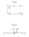
- FIG. 9 is a view showing a map of an exhausted NO X amount NOXA.
- FIG. 10 is a view showing a fuel injection timing.
- FIG. 11 is a view showing an NO X purification rate.
- FIG. 12 is a view showing a map of a hydrocarbon injection amount.
- FIG. 13 is a view showing an NO X discharge rate etc.
- FIG. 14 is a view showing a change in an air-fuel ratio of exhaust gas (A/F) in etc. when switching from a second NO X purification method to a first NO X purification method.
- FIG. 15 is a flow chart for NO X purification control.
- FIG. 16 is a view showing a flow chart etc. showing another embodiment of an NO X purification method determining part A shown in FIG. 15 .
- FIG. 17 is a view showing a flow chart etc. showing still another embodiment of an NO X purification method determining part A shown in FIG. 15 .
- FIG. 18 is a view showing a flow chart etc. showing another embodiment of an NO X purification method determining part A shown in FIG. 15 .
- FIG. 19 is a timing chart showing a change in an air-fuel ratio of exhaust gas (A/F) in etc. when switching from a second NO X purification method to a first NO X purification method.
- FIG. 20 is a timing chart showing a change in an air-fuel ratio of exhaust gas (A/F) in etc. when switching from a second NO X purification method to a first NO X purification method.
- FIG. 21 is a view showing an increase coefficient.
- FIG. 22 is a partial enlarged cross-sectional view of another catalyst for removing NO X .
- FIG. 1 is an overall view of a compression ignition type internal combustion engine.
- 1 indicates an engine body, 2 a combustion chamber of each cylinder, 3 an electronically controlled fuel injector for injecting fuel into each combustion chamber 2 , 4 an intake manifold, and 5 an exhaust manifold.
- the intake manifold 4 is connected through an intake duct 6 to an outlet of a compressor 7 a of an exhaust turbocharger 7 , while an inlet of the compressor 7 a is connected through an intake air amount detector 8 to an air cleaner 9 .
- a throttle valve 10 driven by a step motor is arranged inside the intake duct 6 .
- a cooling device 11 is arranged for cooling the intake air which flows through the inside of the intake duct 6 .
- the engine cooling water is guided to the inside of the cooling device 11 where the engine cooling water is used to cool the intake air.
- the exhaust manifold 5 is connected to an inlet of the exhaust turbine 7 b of the exhaust turbocharger 7 , while the outlet of the exhaust turbine 7 b is connected through an exhaust pipe 12 to an inlet of a hydrocarbon partial oxidation catalyst 13 able to partially oxidize the hydrocarbons HC.
- this hydrocarbon partial oxidation catalyst 13 is comprised of an oxidation catalyst.
- An outlet of the hydrocarbon partial oxidation catalyst, that is, the oxidation catalyst 13 is connected to an inlet of an exhaust purification catalyst 14 , while an outlet of the exhaust purification catalyst 14 is connected to a particulate filter 15 for trapping particulate which is contained in the exhaust gas.
- a hydrocarbon feed valve 16 is arranged for feeding hydrocarbons comprised of diesel oil or other fuel used as fuel of a compression ignition type internal combustion engine.
- diesel oil is used as the hydrocarbons which are fed from the hydrocarbon feed valve 16 .
- the present invention can also be applied to a spark ignition type internal combustion engine which burns fuel under a lean air-fuel ratio. In this case, hydrocarbons comprised of gasoline or other fuel which is used as fuel of a spark ignition type internal combustion engine are fed from the hydrocarbon feed valve 16 .
- the exhaust manifold 5 and the intake manifold 4 are connected with each other through an exhaust gas recirculation (hereinafter referred to as an “EGR”) passage 17 .
- EGR exhaust gas recirculation
- a electronically controlled EGR control valve 18 is arranged inside the EGR passage 17 .
- a cooling device 19 is arranged for cooling EGR gas flowing through the inside of the EGR passage 17 .
- the engine cooling water is guided to the inside of the cooling device 19 where the engine cooling water is used to cool the EGR gas.
- each fuel injector 3 is connected through a fuel feed tube 20 to a common rail 21 .
- This common rail 21 is connected through an electronically controlled variable discharge fuel pump 22 to a fuel tank 23 .
- the fuel which is stored inside of the fuel tank 23 is fed by the fuel pump 22 to the inside of the common rail 21 .
- the fuel which is fed to the inside of the common rail 21 is fed through each fuel feed tube 20 to the fuel injector 3 .
- An electronic control unit 30 is comprised of a digital computer provided with a ROM (read only memory) 32 , a RAM (random access memory) 33 , a CPU (microprocessor) 34 , an input port 35 , and an output port 36 , which are connected with each other by a bidirectional bus 31 .
- a temperature sensor 24 is attached for detecting the temperature of the oxidation catalyst 13 .
- a temperature sensor 25 is attached for detecting the temperature of the exhaust purification catalyst 14 .
- the output signals of these temperature sensors 24 and 25 and intake air amount detector 8 are input through corresponding AD converters 37 to the input port 35 .
- the accelerator pedal 40 has a load sensor 41 connected to it which generates an output voltage proportional to the amount of depression L of the accelerator pedal 40 .
- the output voltage of the load sensor 41 is input through a corresponding AD converter 37 to the input port 35 .
- a crank angle sensor 42 is connected which generates an output pulse every time a crankshaft rotates by, for example, 15°.
- the output port 36 is connected through corresponding drive circuits 38 to each fuel injector 3 , a step motor for driving the throttle valve 10 , the hydrocarbon feed valve 16 , the EGR control valve 18 , and the fuel pump 22 .
- FIG. 2(A) schematically shows a surface part of a catalyst carrier carried on a substrate of an oxidation catalyst 13 .
- a catalyst 51 comprised of platinum Pt or another such precious metal or silver Ag or copper Cu or other such transition metal is carried on a catalyst carrier 50 comprised of alumina.
- FIG. 2(B) schematically shows a surface part of a catalyst carrier which is carried on a substrate of the exhaust purification catalyst 14 .
- a catalyst carrier 52 made of alumina on which precious metal catalysts 53 and 54 are carried.
- a basic layer 55 is formed which includes at least one element selected from potassium K, sodium Na, cesium Cs, or another such alkali metal, barium Ba, calcium Ca, or another such alkali earth metal, a lanthanoid or another such rare earth and silver Ag, copper Cu, iron Fe, iridium Ir, or another metal able to donate electrons to NO x .
- the exhaust gas flows along the top of the catalyst carrier 53 , so the precious metal catalysts 53 and 54 can be said to be carried on the exhaust gas flow surface of the exhaust purification catalyst 14 .
- the surface of the basic layer 55 exhibits basicity, so the surface of the basic layer 55 is called the basic exhaust gas flow surface part 56 .
- the precious metal catalyst 53 is comprised of platinum Pt
- the precious metal catalyst 54 is comprised of rhodium Rh. That is, the precious metal catalysts 53 and 54 which are carried on the catalyst carrier 52 are comprised of platinum Pt and rhodium Rh.
- palladium Pd may be further carried or, instead of rhodium Rh, palladium Pd may be carried. That is, the precious metal catalysts 53 and 54 which are carried on the catalyst carrier 52 are comprised of platinum Pt and at least one of rhodium Rh and palladium Pd.
- the hydrocarbons When hydrocarbons are injected from the hydrocarbon feed valve 16 into the exhaust gas, the hydrocarbons are oxidized on the oxidation catalyst 13 .
- the hydrocarbons are partially oxidized at the oxidation catalyst 13 and the partially oxidized hydrocarbons are used to remove the NO X at the exhaust purification catalyst 14 .
- the hydrocarbons if making the oxidizing strength of the oxidation catalyst 13 too strong, the hydrocarbons end up being oxidized without being partially oxidized at the oxidation catalyst 13 .
- FIG. 3 schematically shows an oxidation reaction which is performed in the oxidation catalyst 13 .
- the hydrocarbons HC which are injected from the hydrocarbon feed valve 16 become radical hydrocarbons HC with a small carbon number due to the catalyst 51 .
- part of the hydrocarbons HC bond with the NO to become nitroso compounds such as shown in FIG. 3
- These radical hydrocarbons etc. produced at the oxidation catalyst 13 are sent to the exhaust purification catalyst 14 .
- FIG. 4 shows the change in the air-fuel ratio (A/F) in of the exhaust gas flowing into the exhaust purification catalyst 14
- FIG. 5 shows the NO X purification rate by the exhaust purification catalyst 14 with respect to the catalyst temperatures TC of the exhaust purification catalyst 14 when changing the air-fuel ratio (A/F) in of the exhaust gas flowing to the exhaust purification catalyst 14 as shown in FIG. 4 .
- FIGS. 6 (A) and 6 (B) schematically show the surface part of the catalyst carrier 52 of the exhaust purification catalyst 14 .
- FIGS. 6(A) and 6(B) show the reaction which is presumed to occur when the air-fuel ratio (A/F) in of the exhaust gas flowing into the exhaust purification catalyst 14 is intermittently reduced within the range of a lean air-fuel ratio as shown in FIG. 4 .
- the air-fuel ratio of the exhaust gas flowing into the exhaust purification catalyst 14 is maintained lean, so the exhaust gas which flows into the exhaust purification catalyst 14 becomes a state of oxygen excess. Therefore, the NO which is contained in the exhaust gas, as shown in FIG. 6(A) , is oxidized on the platinum 53 and becomes NO 2 . Next, this NO 2 is further oxidized and becomes stable nitrate ions NO 3 ⁇ .
- nitrates NO 3 ⁇ when nitrates NO 3 ⁇ are produced, the nitrates NO 3 ⁇ are pulled back in a direction of reduction by the hydrocarbons HC which are sent on to the surface of the basic layer 55 , have the oxygen disassociated, and becomes unstable NO 2 *.
- This unstable NO 2 * is strong in activity.
- this unstable NO 2 ⁇ is called the active NO 2 *.
- This active NO 2 * reacts with the mainly radical hydrocarbons HC which are adhered on the surface of the basic layer 55 or on the rhodium Rh 54 or with the mainly radical hydrocarbons HC contained in the exhaust gas on the rhodium Rh 54 , whereby a reducing intermediate is produced.
- This reducing intermediate is adhered or adsorbed on the surface of the basic layer 55 .
- the first produced reducing intermediate is believed to be a nitro compound R—NO 2 . If this nitro compound R—NO 2 is produced, the result becomes a nitrile compound R—CN, but this nitrile compound R—CN can only survive for an instant in this state, so immediately becomes an isocyanate compound R—NCO.
- This isocyanate compound R—NCO when hydrolyzed, becomes an amine compound R—NH 2 . However, in this case, what is hydrolyzed is considered to be part of the isocyanate compound R—NCO. Therefore, as shown in FIG. 6(A) , the majority of the reducing intermediate which is held or adsorbed on the surface of the basic layer 55 is believed to be the isocyanate compound R—NCO and amine compound R—NH 2 .
- the active NO 2 * reacts with the reducing intermediate R—NCO or R—NH 2 on the rhodium Rh 54 to form N 2 , CO 2 , and H 2 O and consequently the NO x is removed. That is, if no reducing intermediate R—NCO or R—NH 2 is held or adsorbed on the basic layer 55 , the NO X is not removed.
- the air-fuel ratio (A/F) in of the exhaust gas must be lean. It is necessary to hold a sufficient amount of the reducing intermediate R—NCO or R—NH 2 for making the produced active NO 2 * N 2 , CO 2 , and H 2 O on the surface of the basic layer 55 , that is, it is necessary to provide the basic exhaust gas flow surface part 26 for holding the reducing intermediate R—NCO or R—NH 2 .
- precious metal catalysts 53 and 54 are carried on the exhaust gas flow surface of the exhaust purification catalyst 14 , a basic exhaust gas flow surface part 26 is formed around the precious metal catalysts 53 and 54 to hold the produced reducing intermediate R—NCO or R—NH 2 in the exhaust purification catalyst 14 , and the NO X is reduced by the reducing action of the reducing intermediate R—NCO or R—NH 2 held on the basic exhaust gas flow surface part 26 .
- hydrocarbons HC are intermittently fed from the hydrocarbon feed valve 16 by predetermined feed intervals while maintaining the air-fuel ratio of the exhaust gas flowing into the exhaust purification catalyst 14 lean.
- the predetermined feed intervals of the hydrocarbons HC are made the feed interval required for continuing to ensure the presence of the reducing intermediate R—NCO or R—NH 2 on the basic exhaust gas flow surface part 56 .
- the injection interval is made 3 seconds.
- the second NO X purification method will be explained.
- the hydrocarbons HC and the reducing intermediate R—NCO or R—NH 2 disappear from the surface of the basic layer 55 .
- no pullback force in a direction which reduces nitrate ions NO 3 ⁇ , acts on the nitrate ions NO 3 ⁇ produced on the platinum Pt 53. Therefore, at this time, the nitrate ions NO 3 ⁇ diffuse in the basic layer 55 and becomes nitrates as shown in FIG. 7(A) . That is, at this time, the NO X in the exhaust gas is absorbed in the form of nitrates inside the basic layer 55 .
- FIG. 7(B) shows the case where the air-fuel ratio of the exhaust gas which flows into the exhaust purification catalyst 14 is made the stoichiometric air-fuel ratio or rich when the NO x is absorbed in the form of nitrates inside of the basic layer 55 .
- the oxygen concentration in the exhaust gas falls, so the reaction proceeds in the opposite direction (NO 3 ⁇ ⁇ NO 2 ) and consequently the nitrates absorbed in the basic layer 55 become nitrate ions NO 3 ⁇ one by one and, as shown in FIG. 7(B) , are released from the basic layer 55 in the form of NO 2 .
- the released NO 2 is reduced by the hydrocarbons HC and CO contained in the exhaust gas.
- FIG. 8 shows a second NO X purification method utilizing the adsorption and release action of NO X . That is, in this second NO X purification method, as shown in FIG. 8 , when the stored NO X amount ⁇ NOX which is stored in the basic layer 55 exceeds a predetermined allowable amount MAX, the air-fuel ratio (A/F) in of the exhaust gas which flows into the exhaust purification catalyst 14 is temporarily made rich. If the air-fuel ratio (A/F) in of the exhaust gas is made rich, the NO X which was absorbed at the basic layer 55 when the air-fuel ratio (A/F) in of the exhaust gas was lean, is released all at once from the basic layer 55 and reduced. Due to this, the NO X is removed.
- the stored NO X amount ⁇ NOX is, for example, calculated from the NO X amount which is exhausted from the engine.
- the exhausted NO X amount NOXA which is exhausted from the engine per unit time is stored as a function of the engine load L and engine speed N in the form of a map such as shown in FIG. 9 in advance in the ROM 32 .
- the stored NO X amount ⁇ NOX is calculated from this exhausted NO X amount NOXA.
- the period by which the air-fuel ratio (A/F) in of the exhaust gas is made rich is far longer than the period by which the air-fuel ratio (A/F) in of the exhaust gas is lowered, as shown in FIG. 4 , and the period by which the air-fuel ratio (A/F) in of the exhaust gas is made rich is usually 1 minute or more.
- the basic layer 55 performs the role of an absorbent for temporarily absorbing NO X .
- the basic layer 55 temporarily adsorbs the NO x . Therefore, if using term of storage as a term including both absorption and adsorption, at this time, the basic layer 55 performs the role of an NO x storage agent for temporarily storing the NO x .
- the exhaust purification catalyst 14 functions as an NO x storage catalyst which stores the NO x when the air-fuel ratio of the exhaust gas is lean and releases the stored NO x when the oxygen concentration in the exhaust gas falls.
- this second NO X purification method in addition to the combustion use fuel M from the fuel injector 3 , additional fuel W is injected into the combustion chamber 2 whereby the air-fuel ratio (A/F) in of the exhaust gas flowing into the exhaust purification catalyst 14 is made rich.
- the abscissa of FIG. 10 shows the crank angle.
- This additional fuel W is injected at a timing where it is burned, but does not appear as engine output, that is, slightly before ATDC90° after compression top dead center.
- FIG. 11 shows the NO x purification rate when making the exhaust purification catalyst 14 function as an NO x storage catalyst.
- the abscissa of the FIG. 11 shows the catalyst temperature TC of the exhaust purification catalyst 14 .
- the catalyst temperature TC is 300° C. to 400° C.
- an extremely high NO x purification rate is obtained, but when the catalyst temperature TC becomes a 400° C. or higher high temperature, the NO x purification rate falls.
- the NO x purification rate falls because if the catalyst temperature TC becomes 400° C. or more, the nitrates break down by heat and are released in the form of NO 2 from the exhaust purification catalyst 14 . That is, so long as storing NO x in the form of nitrates, when the catalyst temperature TC is high, it is difficult to obtain a high NO x purification rate.
- the first NO x purification method shown from FIG. 4 to FIGS. 6(A) and 6(B) as will be understood from FIGS. 6(A) and 6(B) , nitrates are not formed or even if formed are extremely fine in amount, consequently, as shown in FIG. 5 , even when the catalyst temperature TC is high, a high NO x purification rate is obtained.
- the first NO x purification method shown from FIG. 4 to FIGS. 6(A) and 6(B) can be said to be a new NO x purification method which removes NO X without formation of almost any nitrates when using an exhaust purification catalyst which carries a precious metal catalyst and forms a basic layer which can absorb NO X .
- the nitrates which are detected from the basic layer 53 become much smaller in amount compared with the case of using the second NO X purification method.
- the first NO X purification method to remove NO X , it is necessary to feed a certain amount or more of hydrocarbons by a short period even when the NO X concentration in the exhaust gas is low. Therefore, when the NO X concentration of the exhaust gas is low, the NO X purification efficiency deteriorates.
- the second NO X purification method when the NO X concentration in the exhaust gas is low, the time until the stored NO X amount ⁇ NOX reaches the allowable value MAX becomes longer, and thus the period for making the air-fuel ratio (A/F) in of the exhaust gas rich become longer. Accordingly, the NO X purification efficiency does not become poor. Therefore, when the NO X concentration in the exhaust gas is low, it can be said to be preferable to use the second NO X purification method rather than the first NO X purification method.
- the exhaust purification catalyst 14 on the exhaust purification catalyst 14 , precious metal catalysts 53 and 54 are carried and a basic layer 55 is formed, and the exhaust purification catalyst 14 has the property of reducing the NO x which is contained in the exhaust gas when hydrocarbons are injected from the hydrocarbon feed valve 16 at predetermined feed intervals while maintaining the air-fuel ratio of the exhaust gas flowing into the exhaust purification catalyst 14 is maintained lean and has the property of being increased in the storage amount of NO X which is contained in exhaust gas when the feed intervals of the hydrocarbons are made longer than the predetermined feed intervals.
- a first NO X purification method which injects hydrocarbons from the hydrocarbon feed valve 16 at the predetermined feed intervals while maintaining the air-fuel ratio of the exhaust gas flowing into the exhaust purification catalyst 14 lean so as to remove the NO X contained in the exhaust gas and a second NO X purification method which switches the air-fuel ratio of the exhaust gas which flows to the exhaust purification catalyst 14 from lean to rich by intervals longer than the predetermined feed intervals so as to remove the NO X are selectively used in accordance with the operating state of the engine.
- FIG. 12 to FIG. 15 a representative embodiment according to the present invention will be explained.
- FIG. 12(A) shows the hydrocarbon feed amount QE from the hydrocarbon feed valve 16
- FIG. 12(B) shows the additional fuel amount W which is fed into a combustion chamber 2
- the hydrocarbon feed amount QE is stored as a function of the engine load QE and engine speed N in the form of a map such as shown in FIG. 12(A) in advance in the ROM 32
- the additional fuel amount W is also stored as a function of the engine load QE and engine speed N in the form of a map such as shown in FIG. 12(B) in advance in the ROM 32 .
- FIG. 13(A) shows a discharge rate NOXD of stored NO X which is discharged from the exhaust purification catalyst 14 when the air-fuel ratio (A/F) in of the exhaust gas is lean.
- the NO X which is stored in the form of nitrates is broken down by heat and discharged if the temperature TC of the exhaust purification catalyst 14 rises.
- the NO X discharge rate NOXD that is, the NO X amount NOXD which is discharged per unit time, rapidly rises when the temperature TC of the exhaust purification catalyst 14 exceeds the heat breakdown start temperature of about 450° C.
- FIG. 13(B) shows the storage rate SX of the NO X which is stored in the exhaust purification catalyst 14 when the first NO X purification method is used to perform the purification action of NO X .
- NO X is not stored in the exhaust purification catalyst 14 .
- the flow rate of the exhaust gas becomes faster, that is, if the intake air amount GA increases, the reaction time becomes shorter and the reaction can no longer be sufficiently performed, so active NO 2 * is not formed and the NO X which is absorbed at the basic layer 55 increases. Therefore, as shown in FIG. 13(B) , when the intake air amount GA becomes larger than a certain value, the NO X storage rate SX starts to increase.
- the amount of NO X stored per unit time becomes the value SX ⁇ NOXA of the NO X storage rate SX multiplied with the NO X amount NOXA exhausted per unit time.
- SX ⁇ NOXA is cumulatively added to calculate the stored NO X amount which is stored when the first NO x purification method is used to perform the NO X purification action.
- the stored NO X amount which is calculated at the time of the first NO X purification method is used as the basis to start to calculate the stored NO X amount.
- the NO X storage amount which was calculated when the first NO X purification method is used and the NO X storage amount which was calculated after switching to the second NO X purification method are totaled up.
- this total value ⁇ NOX exceeds a predetermined allowable value MAX, the air-fuel ratio of the exhaust gas flowing into the exhaust purification catalyst 14 is made temporarily rich.
- the timing at which the air-fuel ratio (A/F) in of the exhaust gas is made rich when switched to the second NO X purification method becomes slower and consequently part of the NO X is exhausted into the atmosphere without being stored.
- the NO X storage amount of the time when the first NO X purification method is used is taken into consideration. Therefore, the above such problem does not arise.
- the air-fuel ratio (A/F) in of the exhaust gas rich, it is possible to reduce the stored NO X which remained in the exhaust purification catalyst 14 and consequently possible to block the NO X from being exhausted into the atmosphere. Therefore, in an embodiment of the present invention, as shown in FIG. 14 , when switched from the second NO X purification method to the first NO X purification method, the air-fuel ratio of the exhaust gas which flows into the exhaust purification catalyst 14 is temporarily made rich to release and reduce the NO X which was stored in the exhaust purification catalyst 14 .
- FIG. 14 shows the change of the air-fuel ratio (A/F) in of the exhaust gas which flows into the exhaust purification catalyst 14 and the stored NO X amount ⁇ NOX which is stored in the exhaust purification catalyst 14 .
- A/F air-fuel ratio
- the NO X purification action by the first NO X purification method is not performed so long as the oxidation catalyst 13 is not activated. Therefore, in an embodiment of the present invention, the first NO X purification method is used only when the temperature TB of the oxidation catalyst 13 becomes the activation temperature TB 0 or more. When the temperature TB of the oxidation catalyst 13 is lower than the activation temperature TB 0 , use of the first NO X purification method is prohibited. At this time, that is, when the temperature TB of the oxidation catalyst 13 is lower than the activation temperature TB 0 , the second NO X purification method is used.
- the first NO X purification method when the temperature TB of the oxidation catalyst 13 is the activation temperature TB 0 or more, either of the first NO X purification method or the second NO X purification method is used.
- the first NO X purification method when using the first NO X purification method would result in a higher NO X purification efficiency compared with using the second NO X purification method, the first NO X purification method is used, while when using the second NO X purification method would result in a higher NO X purification efficiency compared with using the first NO X purification method, the second NO X purification method is used.
- FIG. 15 shows the NO X purification control routine for executing the representative embodiment of the present invention. This routine is executed by interruption every predetermined time interval.
- the routine proceeds to an NO X purification method determining part A for determining whether to use the first NO X purification method or use the second NO X purification method.
- this NO X purification method determination part A first, at step 61 , it is judged if the temperature TB of the oxidation catalyst 13 is the activation temperature TB 0 or more. When TB ⁇ TB 0 , it is judged that the second NO X purification method should be used. At this time, the routine proceeds to step 64 .
- the routine proceeds to step 62 where the NO X purification efficiency F 1 when using the first NO X purification method and the NO X purification efficiency F 2 when using the second NO X purification method are calculated.
- the NO X purification efficiencies F 1 and F 2 express the amounts of consumption of fuel or hydrocarbons per unit time required for obtaining a unit NO X purification rate.
- the NO X purification efficiency F 1 is calculated from the hydrocarbon feed amount QE and hydrocarbon injection interval shown in FIG. 12A and the NO X purification rate shown in FIG. 5
- the NO X purification efficiency F 2 is calculated from the additional fuel amount W shown in FIG. 12B , the interval between timings where the rich air-fuel ratio is set in FIG. 8 , and the NO X purification rate shown in FIG. 11 .
- step 63 it is judged if the NO X purification efficiency F 1 is higher than the NO X purification efficiency F 2 .
- F 1 ⁇ F 2 it is judged that the first NO X purification method should be used.
- the routine proceeds to step 68 .
- F 1 ⁇ F 2 it is judged that the second NO X purification method should be used, and the routine proceeds to step 64 .
- step 64 the exhausted NO X amount NOXA shown in FIG. 9 is added to ⁇ NOX to calculate the stored NO X amount ⁇ NOX.
- step 65 it is judged if the stored NO X amount ⁇ NOX exceeds the allowable value MAX.
- the routine proceeds to step 66 where the additional fuel amount W is calculated from the map shown in FIG. 12B , then the additional fuel injection action is performed.
- step 67 ⁇ NOX is cleared.
- step 68 it is judged if stored NO X processing is being performed for processing the stored NO X remaining inside the exhaust purification catalyst 14 .
- the routine proceeds to step 69 where it is judged if a decision to switch from the second NO X purification method to the first NO X purification method has now been made. If a decision to switch from the second NO X purification method to the first NO X purification method has now been made, the routine proceeds to step 70 where it is judged if the stored NO X amount ⁇ NOX is smaller than a predetermined small value MIN.
- step 71 stored NO X processing is performed.
- the air-fuel ratio (A/F) in of the exhaust gas is temporarily made rich.
- step 72 ⁇ NOX is cleared. Note that, when the stored NO X processing has started, the routine jumps from step 68 to step 71 until the stored NO X processing is completed.
- step 73 the routine proceeds to step 73 .
- step 70 the hydrocarbon feed amount QE is calculated from the map such as shown in FIG. 12(A) , so hydrocarbon injection processing is performed.
- step 74 the following formula is used as the basis to calculate the NO X amount ⁇ NOX which is stored in the exhaust purification catalyst 14 during an NO X purification action by the first NO X purification method. ⁇ NOX ⁇ NOX+SX ⁇ NOX A ⁇ NOX D
- SX ⁇ NOXA is the NO X amount which is stored per unit time and NOXD is the discharge rate shown in FIG. 13A .
- NOXA is added to the ⁇ NOX calculated at step 74 .
- FIG. 16 shows another embodiment.
- the engine operating region where the NO X purification efficiency F 2 becomes higher than the NO X purification efficiency F 1 is set in advance as shown by the hatching in FIG. 16(A) , for example, as a function of the engine load L and engine speed N.
- the NO X purification method is determined in accordance with FIG. 16(A) .
- FIG. 16(B) shows another embodiment of the NO X purification method determining part A of FIG. 15 .
- the routine proceeds to step 64 of FIG. 15 .
- the routine proceeds to step 61 a where it is judged if the operating state of the engine is a region shown by the hatching in FIG. 16(A) where the second NO X purification method should be used.
- the routine proceeds to step 64 of FIG. 15 .
- the routine proceeds to step 68 of FIG. 15 .
- FIG. 17 shows still another embodiment of the NO X purification method determining part A of FIG. 15 . That is, the NO X purification rate when using the first NO X purification method, as shown in FIG. 5 , is rapidly lowered when the temperature TC of the exhaust purification catalyst 14 becomes the limit temperature TC 0 or less. As opposed to this, as shown in FIG. 11 , the NO X purification rate when using the second NO X purification method falls relatively slowly when the temperature TC of the exhaust purification catalyst 14 falls.
- the first NO X purification method when the temperature TC of the exhaust purification catalyst 14 is higher than the limit temperature TC 0 , the first NO X purification method is used, while when the temperature TC of the exhaust purification catalyst 14 is lower than the limit temperature TC 0 , the second NO X purification method is used.
- step 61 when the temperature TB of the oxidation catalyst 13 is lower than the activation temperature TB 0 , it is judged that the second NO X purification method should be used then the routine proceeds to step 64 of FIG. 15 .
- the routine proceeds to step 61 a where it is judged if the temperature TC of the exhaust purification catalyst 14 is higher than the limit temperature TC 0 .
- the routine proceeds to step 64 of FIG. 15 .
- TC ⁇ T 0 it is judged that the first NO X purification method should be used then the routine proceeds to step 68 of FIG. 15 .
- FIG. 18 shows still another embodiment of the NO X purification method determining part A of FIG. 15 . That is, the first NO X purification method can give a high NO X purification rate as compared with the second NO X purification method when the NO X amount to be reduced is large, that is, when the NO X concentration in the exhaust gas is high. Therefore, in this embodiment, it is judged whether to use the first NO X purification method or to use the second NO X purification method by whether the NO X concentration D in the exhaust gas exceeds a set value D 0 .
- step 61 when the temperature TB of the oxidation catalyst 13 is lower than the activation temperature TB 0 , it is judged that the second NO X purification method should be used, then the routine proceeds to step 64 of FIG. 15 .
- the routine proceeds to step 61 a where it is judged if the temperature TC of the exhaust purification catalyst 14 is higher than the limit temperature TC 0 .
- the routine proceeds to step 64 of FIG. 15 .
- step 61 b it is judged if the NO X concentration D in the exhaust gas which is detected by for example, the NO X concentration sensor is higher than the set value D 0 .
- D ⁇ D 0 the routine proceeds to step 64 of FIG. 15 .
- D ⁇ D 0 it is judged that the first NO X purification method should be used, then the routine proceeds to step 68 of FIG. 15 .
- FIG. 19 shows another embodiment of the stored NO X processing which is performed at step 71 of FIG. 15 .
- the air-fuel ratio (A/F) in of the exhaust gas flowing into the exhaust purification catalyst 14 is made rich.
- the amount of hydrocarbons which is fed from the hydrocarbon feed valve 16 is increased so that the air-fuel ratio (A/F) in of the exhaust gas is made rich.
- the air-fuel ratio (A/F) in of the exhaust gas is made rich by stopping the injection of the additional fuel and increasing the feed amount of hydrocarbons.
- FIG. 20 shows still another embodiment of the stored NO X processing which is performed at step 71 of FIG. 15 .
- the NO X purification action is started by the first NO X purification method, then the air-fuel ratio (A/F) in of the exhaust gas flowing into the exhaust purification catalyst 14 is made rich.
- this discharged NO X is reduced by feeding additional fuel to the combustion chamber 2 or increasing the feed amount of hydrocarbons to make the air-fuel ratio (A/F) in of the exhaust gas rich.
- the sulfur which is contained in the exhaust gas sticks to the surface of the precious metal, that is, if the precious metal is poisoned by sulfur, active NO 2 * becomes harder to produce. Therefore, it is preferable to increase the feed amount of hydrocarbons QE as the sulfur poisoning amount of the precious metal is increased so that the amount of production of active NO 2 * does not fall even if the precious metal is poisoned by sulfur.
- the increase coefficient for the hydrocarbon feed amount QE is increased along with the increase in the sulfur poisoning amount so that the amount of production of active NO 2 * does not fall even if the sulfur poisoning amount is increased.
- FIG. 22 shows the case of forming the hydrocarbon partial oxidation catalyst 13 and the exhaust purification catalyst 14 shown in FIG. 1 by a single catalyst.
- This catalyst is for example provided with a large number of exhaust gas channels extending in the direction of flow of the exhaust gas.
- FIG. 22 shows an enlarged cross-sectional view of the surface part of the inner circumferential wall 80 of an exhaust gas channel of the catalyst.
- a bottom coat layer 81 is formed on the surface of the inner circumferential wall 80 of the exhaust gas channel.
- a top coat layer 82 is formed on this bottom coat layer 81 .
- both the coat layers 81 and 82 are comprised of powder aggregates.
- FIG. 22 shows enlarged views of the powder forming the coat layers 81 and 82 . From the enlarged views of the powder, it is learned that the top coat layer 82 is comprised of the hydrocarbon partial oxidation catalyst shown in FIG. 2(A) , for example, an oxidation catalyst, while the bottom coat layer 81 is comprised of the exhaust purification catalyst shown in FIG. 2(B) .
- the top coat layer 82 is comprised of the hydrocarbon partial oxidation catalyst shown in FIG. 2(A) , for example, an oxidation catalyst
- the bottom coat layer 81 is comprised of the exhaust purification catalyst shown in FIG. 2(B) .
- the hydrocarbons HC which are contained in the exhaust gas diffuse inside the top coat layer 82 and are partially oxidized.
- the partially oxidized hydrocarbons diffuse inside the bottom coat layer 81 . That is, in the example shown in FIG. 22 as well, in the same way as the example shown in FIG. 1 , the hydrocarbon partial oxidation catalyst and the exhaust purification catalyst are arranged so that the hydrocarbons which were partially oxidized at the hydrocarbon partial oxidation catalyst flow to the exhaust purification catalyst.
- the NO X which is contained in the exhaust gas diffuses to the inside of the bottom coat layer 81 and becomes active NO 2 *.
- the reducing intermediate R—NCO or R—NH 2 is produced from the active NO 2 * and the partially oxidized hydrocarbons.
- the active NO 2 * reacts with the reducing intermediate R—HCO or R—NH 2 to become N 2 , CO 2 , and H 2 O.
- the hydrocarbons which are injected from the hydrocarbon feed valve 16 are partially oxidized inside of the exhaust purification catalyst 14 . Furthermore, inside of the exhaust purification catalyst 14 , active NO 2 * is produced from the NO X which is contained in the exhaust gas. Inside of the exhaust purification catalyst 14 , the reducing intermediate R—NCO and R—NH 2 is produced from these active NO 2 * and partially oxidized hydrocarbons. Furthermore, the active NO 2 * reacts with the reducing intermediate R—NCO or R—NH 2 to become N 2 , CO 2 , and H 2 O. That is, in this embodiment, the exhaust purification catalyst 14 for reacting the hydrocarbons injected from the hydrocarbon feed valve 16 and partially oxidized and the NO X contained in the exhaust gas is arranged inside of the engine exhaust passage downstream of the hydrocarbon feed valve 16 .
Landscapes
- Engineering & Computer Science (AREA)
- Chemical & Material Sciences (AREA)
- Combustion & Propulsion (AREA)
- General Engineering & Computer Science (AREA)
- Mechanical Engineering (AREA)
- Chemical Kinetics & Catalysis (AREA)
- Health & Medical Sciences (AREA)
- Toxicology (AREA)
- General Chemical & Material Sciences (AREA)
- Oil, Petroleum & Natural Gas (AREA)
- Analytical Chemistry (AREA)
- Environmental & Geological Engineering (AREA)
- Biomedical Technology (AREA)
- Exhaust Gas After Treatment (AREA)
- Exhaust Gas Treatment By Means Of Catalyst (AREA)
Abstract
A method of purifying NOX contained in exhaust gas, the method including a first NOX purification method and a second NOX purification method, wherein the first NOX purification method and the second NOX purification method include injecting hydrocarbons into an exhaust gas passage at predetermined feed intervals, wherein in the first method, the injected hydrocarbons are partially oxidized and an air-fuel ratio flowing into an exhaust purification catalyst is lean, and in the second method, the injection of the hydrocarbons occurs at intervals longer than the predetermined feed intervals in the first method, and an air-fuel ratio is switched from lean to rich.
Description
This is a Continuation of application Ser. No. 13/202,733 filed Sep. 30, 2011, which in turn is a National Stage Application of PCT/JP2010/054740 filed Mar. 15, 2010. The disclosure of the prior applications is hereby incorporated by reference herein in its entirety.
The present invention relates to an exhaust purification system of an internal combustion engine.
Known in the art is an internal combustion engine which arranges, in an engine exhaust passage, an NOx storage catalyst which stores NOx which is contained in exhaust gas when the air-fuel ratio of the inflowing exhaust gas is lean and which releases the stored NOx, when the air-fuel ratio of the inflowing exhaust gas becomes rich, which arranges, in the engine exhaust passage upstream of the NOx storage catalyst, an oxidation catalyst which has an adsorption function, and which feeds hydrocarbons into the engine exhaust passage upstream of the oxidation catalyst to make the air-fuel ratio of the exhaust gas flowing into the NOx storage catalyst rich when releasing NOx from the NOx storage catalyst (for example, see Patent Literature 1).
In this internal combustion engine, the hydrocarbons which are fed when releasing NOx from the NOx storage catalyst are made gaseous hydrocarbons at the oxidation catalyst, and the gaseous hydrocarbons are fed to the NOx storage catalyst. As a result, the NOx which is released from the NOx storage catalyst is reduced well.
- Patent Literature 1: Japanese Patent No. 3969450
However, there is the problem that when the NOx storage catalyst becomes a high temperature, the NOx purification rate falls.
An object of the present invention is to provide an exhaust purification system of an internal combustion engine which can obtain a high NOx purification rate even if the temperature of the exhaust purification catalyst becomes a high temperature.
According to the present invention, there is provided an exhaust purification system of an internal combustion engine wherein a hydrocarbon feed valve for feeding hydrocarbons is arranged inside an engine exhaust passage, an exhaust purification catalyst for reacting NOx contained in exhaust gas and hydrocarbons which are injected from the hydrocarbon feed valve and are partially oxidized is arranged in the engine exhaust passage downstream of the hydrocarbon feed valve, a precious metal catalyst is carried on the exhaust purification catalyst and a basic layer is formed on the exhaust purification catalyst, the exhaust purification catalyst has a property of reducing the NOX which is contained in the exhaust gas when hydrocarbons are injected from the hydrocarbon feed valve at predetermined feed intervals while maintaining an air-fuel ratio of an exhaust gas flowing into the exhaust purification catalyst lean and has a property of being increased in storage amount of NOX which is contained in the exhaust gas when the feed intervals of the hydrocarbons are longer than the predetermined feed intervals, and, at the time of engine operation, a first NOX purification method which injects hydrocarbons from the hydrocarbon feed valve at the predetermined feed intervals while maintaining the air-fuel ratio of the exhaust gas flowing into the exhaust purification catalyst lean so as to remove the NOX contained in the exhaust gas and a second NOX purification method which switches the air-fuel ratio of the exhaust gas which flows to the exhaust purification catalyst from lean to rich by intervals longer than the predetermined feed intervals so as to remove the NOX are selectively used in accordance with an operating state of an engine.
By selectively using the first NOX purification method and the second NOX purification method, it is possible to obtain a high NOX purification rate regardless of the operating state of the engine.
Referring to FIG. 1, 1 indicates an engine body, 2 a combustion chamber of each cylinder, 3 an electronically controlled fuel injector for injecting fuel into each combustion chamber 2, 4 an intake manifold, and 5 an exhaust manifold. The intake manifold 4 is connected through an intake duct 6 to an outlet of a compressor 7 a of an exhaust turbocharger 7, while an inlet of the compressor 7 a is connected through an intake air amount detector 8 to an air cleaner 9. Inside the intake duct 6, a throttle valve 10 driven by a step motor is arranged. Furthermore, around the intake duct 6, a cooling device 11 is arranged for cooling the intake air which flows through the inside of the intake duct 6. In the embodiment shown in FIG. 1 , the engine cooling water is guided to the inside of the cooling device 11 where the engine cooling water is used to cool the intake air.
On the other hand, the exhaust manifold 5 is connected to an inlet of the exhaust turbine 7 b of the exhaust turbocharger 7, while the outlet of the exhaust turbine 7 b is connected through an exhaust pipe 12 to an inlet of a hydrocarbon partial oxidation catalyst 13 able to partially oxidize the hydrocarbons HC. In the embodiment shown in FIG. 1 , this hydrocarbon partial oxidation catalyst 13 is comprised of an oxidation catalyst. An outlet of the hydrocarbon partial oxidation catalyst, that is, the oxidation catalyst 13, is connected to an inlet of an exhaust purification catalyst 14, while an outlet of the exhaust purification catalyst 14 is connected to a particulate filter 15 for trapping particulate which is contained in the exhaust gas. Inside of the exhaust pipe 12 upstream of the oxidation catalyst 13, a hydrocarbon feed valve 16 is arranged for feeding hydrocarbons comprised of diesel oil or other fuel used as fuel of a compression ignition type internal combustion engine. In the embodiment shown in FIG. 1 , diesel oil is used as the hydrocarbons which are fed from the hydrocarbon feed valve 16. Note that, the present invention can also be applied to a spark ignition type internal combustion engine which burns fuel under a lean air-fuel ratio. In this case, hydrocarbons comprised of gasoline or other fuel which is used as fuel of a spark ignition type internal combustion engine are fed from the hydrocarbon feed valve 16.
On the other hand, the exhaust manifold 5 and the intake manifold 4 are connected with each other through an exhaust gas recirculation (hereinafter referred to as an “EGR”) passage 17. Inside the EGR passage 17, a electronically controlled EGR control valve 18 is arranged. Further, around the EGR passage 17, a cooling device 19 is arranged for cooling EGR gas flowing through the inside of the EGR passage 17. In the embodiment shown in FIG. 1 , the engine cooling water is guided to the inside of the cooling device 19 where the engine cooling water is used to cool the EGR gas. On the other hand, each fuel injector 3 is connected through a fuel feed tube 20 to a common rail 21. This common rail 21 is connected through an electronically controlled variable discharge fuel pump 22 to a fuel tank 23. The fuel which is stored inside of the fuel tank 23 is fed by the fuel pump 22 to the inside of the common rail 21. The fuel which is fed to the inside of the common rail 21 is fed through each fuel feed tube 20 to the fuel injector 3.
An electronic control unit 30 is comprised of a digital computer provided with a ROM (read only memory) 32, a RAM (random access memory) 33, a CPU (microprocessor) 34, an input port 35, and an output port 36, which are connected with each other by a bidirectional bus 31. At the oxidation catalyst 13, a temperature sensor 24 is attached for detecting the temperature of the oxidation catalyst 13. At the exhaust purification catalyst 14, a temperature sensor 25 is attached for detecting the temperature of the exhaust purification catalyst 14. The output signals of these temperature sensors 24 and 25 and intake air amount detector 8 are input through corresponding AD converters 37 to the input port 35. Further, the accelerator pedal 40 has a load sensor 41 connected to it which generates an output voltage proportional to the amount of depression L of the accelerator pedal 40. The output voltage of the load sensor 41 is input through a corresponding AD converter 37 to the input port 35. Furthermore, at the input port 35, a crank angle sensor 42 is connected which generates an output pulse every time a crankshaft rotates by, for example, 15°. On the other hand, the output port 36 is connected through corresponding drive circuits 38 to each fuel injector 3, a step motor for driving the throttle valve 10, the hydrocarbon feed valve 16, the EGR control valve 18, and the fuel pump 22.
On the other hand, FIG. 2(B) schematically shows a surface part of a catalyst carrier which is carried on a substrate of the exhaust purification catalyst 14. At this exhaust purification catalyst 14, as shown in FIG. 2(B) , for example, there is provided a catalyst carrier 52 made of alumina on which precious metal catalysts 53 and 54 are carried. Furthermore, on this catalyst carrier 52, a basic layer 55 is formed which includes at least one element selected from potassium K, sodium Na, cesium Cs, or another such alkali metal, barium Ba, calcium Ca, or another such alkali earth metal, a lanthanoid or another such rare earth and silver Ag, copper Cu, iron Fe, iridium Ir, or another metal able to donate electrons to NOx. The exhaust gas flows along the top of the catalyst carrier 53, so the precious metal catalysts 53 and 54 can be said to be carried on the exhaust gas flow surface of the exhaust purification catalyst 14. Further, the surface of the basic layer 55 exhibits basicity, so the surface of the basic layer 55 is called the basic exhaust gas flow surface part 56.
In FIG. 2(B) , the precious metal catalyst 53 is comprised of platinum Pt, while the precious metal catalyst 54 is comprised of rhodium Rh. That is, the precious metal catalysts 53 and 54 which are carried on the catalyst carrier 52 are comprised of platinum Pt and rhodium Rh. Note that, on the catalyst carrier 52 of the exhaust purification catalyst 14, in addition to platinum Pt and rhodium Rh, palladium Pd may be further carried or, instead of rhodium Rh, palladium Pd may be carried. That is, the precious metal catalysts 53 and 54 which are carried on the catalyst carrier 52 are comprised of platinum Pt and at least one of rhodium Rh and palladium Pd.
When hydrocarbons are injected from the hydrocarbon feed valve 16 into the exhaust gas, the hydrocarbons are oxidized on the oxidation catalyst 13. In the present invention, at this time, the hydrocarbons are partially oxidized at the oxidation catalyst 13 and the partially oxidized hydrocarbons are used to remove the NOX at the exhaust purification catalyst 14. In this case, if making the oxidizing strength of the oxidation catalyst 13 too strong, the hydrocarbons end up being oxidized without being partially oxidized at the oxidation catalyst 13. To make the hydrocarbons partially oxidize, it is necessary to weaken the oxidizing strength of the oxidation catalyst 13. Therefore, in an embodiment of the present invention, as an oxidation catalyst 13, a catalyst with a little carried amount of the precious metal catalyst, a catalyst carrying a base metal, or a catalyst with a small volume is used.
Next, referring to FIG. 4 to FIG. 6 , a first NOX purification method discovered by the inventors will be explained.
Note that, FIG. 4 shows the change in the air-fuel ratio (A/F) in of the exhaust gas flowing into the exhaust purification catalyst 14, while FIG. 5 shows the NOX purification rate by the exhaust purification catalyst 14 with respect to the catalyst temperatures TC of the exhaust purification catalyst 14 when changing the air-fuel ratio (A/F) in of the exhaust gas flowing to the exhaust purification catalyst 14 as shown in FIG. 4 .
Now, the inventors engaged in repeated research on NOX purification over a long period of time and, in the process of research, learned that, as shown in FIG. 4 , if intermittently lowering the air-fuel ratio (A/F) in of the exhaust gas flowing into the exhaust purification catalyst 14 by later explained certain time intervals within a range of a lean air-fuel ratio, an extremely high NOX purification rate is obtained even in a 400° C. or more high temperature region as shown in FIG. 5 . Furthermore, it was learned that, at this time, a large amount of a reducing intermediate containing nitrogen and hydrocarbons continues to be held or adsorbed on the surface of the basic layer 55, that is, on the basic exhaust gas flow surface part 56 of the exhaust purification catalyst 14, and this reducing intermediate plays a central role in obtaining a high NOX purification rate.
Next, this will be explained with reference to FIGS. 6(A) and 6(B). Note that, these FIGS. 6(A) and 6(B) schematically show the surface part of the catalyst carrier 52 of the exhaust purification catalyst 14. These FIGS. 6(A) and 6(B) show the reaction which is presumed to occur when the air-fuel ratio (A/F) in of the exhaust gas flowing into the exhaust purification catalyst 14 is intermittently reduced within the range of a lean air-fuel ratio as shown in FIG. 4 .
That is, as will be understood from FIG. 4 , the air-fuel ratio of the exhaust gas flowing into the exhaust purification catalyst 14 is maintained lean, so the exhaust gas which flows into the exhaust purification catalyst 14 becomes a state of oxygen excess. Therefore, the NO which is contained in the exhaust gas, as shown in FIG. 6(A) , is oxidized on the platinum 53 and becomes NO2. Next, this NO2 is further oxidized and becomes stable nitrate ions NO3 −.
On the other hand, when nitrates NO3 − are produced, the nitrates NO3 − are pulled back in a direction of reduction by the hydrocarbons HC which are sent on to the surface of the basic layer 55, have the oxygen disassociated, and becomes unstable NO2*. This unstable NO2* is strong in activity. Below, this unstable NO2 − is called the active NO2*. This active NO2*, as shown in FIG. 6(A) , reacts with the mainly radical hydrocarbons HC which are adhered on the surface of the basic layer 55 or on the rhodium Rh 54 or with the mainly radical hydrocarbons HC contained in the exhaust gas on the rhodium Rh 54, whereby a reducing intermediate is produced. This reducing intermediate is adhered or adsorbed on the surface of the basic layer 55.
Note that, at this time, the first produced reducing intermediate is believed to be a nitro compound R—NO2. If this nitro compound R—NO2 is produced, the result becomes a nitrile compound R—CN, but this nitrile compound R—CN can only survive for an instant in this state, so immediately becomes an isocyanate compound R—NCO. This isocyanate compound R—NCO, when hydrolyzed, becomes an amine compound R—NH2. However, in this case, what is hydrolyzed is considered to be part of the isocyanate compound R—NCO. Therefore, as shown in FIG. 6(A) , the majority of the reducing intermediate which is held or adsorbed on the surface of the basic layer 55 is believed to be the isocyanate compound R—NCO and amine compound R—NH2.
On the other hand, as shown in FIG. 6(B) , the active NO2* reacts with the reducing intermediate R—NCO or R—NH2 on the rhodium Rh 54 to form N2, CO2, and H2O and consequently the NOx is removed. That is, if no reducing intermediate R—NCO or R—NH2 is held or adsorbed on the basic layer 55, the NOX is not removed. Therefore, to obtain a high NOX purification rate, it is necessary to ensure the continuous presence of a sufficient amount of the reducing intermediate R—NCO or R—NH2 for making the active NO2* N2, CO2, and H2O on the basic layer 55, that is, the basic exhaust gas flow surface part 26, at all times.
That is, as shown in FIGS. 6(A) and 6(B) , to oxidize the NO on the platinum Pt 53, the air-fuel ratio (A/F) in of the exhaust gas must be lean. It is necessary to hold a sufficient amount of the reducing intermediate R—NCO or R—NH2 for making the produced active NO2* N2, CO2, and H2O on the surface of the basic layer 55, that is, it is necessary to provide the basic exhaust gas flow surface part 26 for holding the reducing intermediate R—NCO or R—NH2.
Therefore, as shown in FIGS. 6(A) and 6(B) , to react the NOX contained in the exhaust gas and the partially oxidized hydrocarbons and produce a reducing intermediate R—NCO or R—NH2 containing nitrogen and hydrocarbon, precious metal catalysts 53 and 54 are carried on the exhaust gas flow surface of the exhaust purification catalyst 14, a basic exhaust gas flow surface part 26 is formed around the precious metal catalysts 53 and 54 to hold the produced reducing intermediate R—NCO or R—NH2 in the exhaust purification catalyst 14, and the NOX is reduced by the reducing action of the reducing intermediate R—NCO or R—NH2 held on the basic exhaust gas flow surface part 26. Therefore, in this first NOX purification method, hydrocarbons HC are intermittently fed from the hydrocarbon feed valve 16 by predetermined feed intervals while maintaining the air-fuel ratio of the exhaust gas flowing into the exhaust purification catalyst 14 lean. The predetermined feed intervals of the hydrocarbons HC are made the feed interval required for continuing to ensure the presence of the reducing intermediate R—NCO or R—NH2 on the basic exhaust gas flow surface part 56.
In this case, if the injection amount becomes too large or the injection interval becomes too short, the amount of hydrocarbons becomes excessive and a large amount of hydrocarbons HC is exhausted from the exhaust purification catalyst 14, while if the injection amount becomes too small or the injection interval becomes too long, the reducing intermediate R—NCO or R—NH2 can no longer remain on the basic exhaust gas flow surface part 56. Therefore, in this case, what is important is setting the injection amount and injection interval of hydrocarbons so that so that no excess hydrocarbons HC are exhausted from the exhaust purification catalyst 14 and so that the reducing intermediate R—NCO or the R—NH2 continues on the basic exhaust gas flow surface part 26. Incidentally, in the example shown in FIG. 4 , the injection interval is made 3 seconds.
Next, while referring to FIG. 7 to FIG. 11 , the second NOX purification method will be explained. In the case shown in FIG. 4 , if making the feed intervals of the hydrocarbons HC longer than the above-mentioned predetermined feed intervals, the hydrocarbons HC and the reducing intermediate R—NCO or R—NH2 disappear from the surface of the basic layer 55. At this time, no pullback force in a direction, which reduces nitrate ions NO3 −, acts on the nitrate ions NO3 − produced on the platinum Pt 53. Therefore, at this time, the nitrate ions NO3 − diffuse in the basic layer 55 and becomes nitrates as shown in FIG. 7(A) . That is, at this time, the NOX in the exhaust gas is absorbed in the form of nitrates inside the basic layer 55.
On the other hand, FIG. 7(B) shows the case where the air-fuel ratio of the exhaust gas which flows into the exhaust purification catalyst 14 is made the stoichiometric air-fuel ratio or rich when the NOx is absorbed in the form of nitrates inside of the basic layer 55. In this case, the oxygen concentration in the exhaust gas falls, so the reaction proceeds in the opposite direction (NO3 −→NO2) and consequently the nitrates absorbed in the basic layer 55 become nitrate ions NO3 − one by one and, as shown in FIG. 7(B) , are released from the basic layer 55 in the form of NO2. Next, the released NO2 is reduced by the hydrocarbons HC and CO contained in the exhaust gas.
The stored NOX amount ΣNOX is, for example, calculated from the NOX amount which is exhausted from the engine. In an embodiment of the present invention, the exhausted NOX amount NOXA which is exhausted from the engine per unit time is stored as a function of the engine load L and engine speed N in the form of a map such as shown in FIG. 9 in advance in the ROM 32. The stored NOX amount ΣNOX is calculated from this exhausted NOX amount NOXA. The period by which the air-fuel ratio (A/F) in of the exhaust gas is made rich is far longer than the period by which the air-fuel ratio (A/F) in of the exhaust gas is lowered, as shown in FIG. 4 , and the period by which the air-fuel ratio (A/F) in of the exhaust gas is made rich is usually 1 minute or more.
In the second NOX purification method, when the air-fuel ratio (A/F) in of the exhaust gas is lean, the NOX which is contained in the exhaust gas is absorbed in the basic layer 55. Therefore, the basic layer 55 performs the role of an absorbent for temporarily absorbing NOX. Note that, at this time, sometimes the basic layer 55 temporarily adsorbs the NOx. Therefore, if using term of storage as a term including both absorption and adsorption, at this time, the basic layer 55 performs the role of an NOx storage agent for temporarily storing the NOx. That is, if the ratio of the air and fuel (hydrocarbons) which are fed into the engine intake passage, combustion chambers 2, and exhaust passage upstream of the exhaust purification catalyst 14 is called the air-fuel ratio of the exhaust gas, in this second NOX purification method, the exhaust purification catalyst 14 functions as an NOx storage catalyst which stores the NOx when the air-fuel ratio of the exhaust gas is lean and releases the stored NOx when the oxygen concentration in the exhaust gas falls.
Further, in this second NOX purification method, as shown in FIG. 10 , in addition to the combustion use fuel M from the fuel injector 3, additional fuel W is injected into the combustion chamber 2 whereby the air-fuel ratio (A/F) in of the exhaust gas flowing into the exhaust purification catalyst 14 is made rich. Note that, the abscissa of FIG. 10 shows the crank angle. This additional fuel W is injected at a timing where it is burned, but does not appear as engine output, that is, slightly before ATDC90° after compression top dead center. Of course, in this case, it is also possible to make the feed amount of hydrocarbons from the hydrocarbon feed valve 16 increase so as to make the air-fuel ratio (A/F) in of the exhaust gas rich.
In this way, when the catalyst temperature TC becomes 400° C. or more, the NOx purification rate falls because if the catalyst temperature TC becomes 400° C. or more, the nitrates break down by heat and are released in the form of NO2 from the exhaust purification catalyst 14. That is, so long as storing NOx in the form of nitrates, when the catalyst temperature TC is high, it is difficult to obtain a high NOx purification rate. However, in the first NOx purification method shown from FIG. 4 to FIGS. 6(A) and 6(B) , as will be understood from FIGS. 6(A) and 6(B) , nitrates are not formed or even if formed are extremely fine in amount, consequently, as shown in FIG. 5 , even when the catalyst temperature TC is high, a high NOx purification rate is obtained.
That is, the first NOx purification method shown from FIG. 4 to FIGS. 6(A) and 6(B) can be said to be a new NOx purification method which removes NOX without formation of almost any nitrates when using an exhaust purification catalyst which carries a precious metal catalyst and forms a basic layer which can absorb NOX. In actuality, when using this first NOx purification method, the nitrates which are detected from the basic layer 53 become much smaller in amount compared with the case of using the second NOX purification method.
On the other hand, to use the first NOX purification method to remove NOX, it is necessary to feed a certain amount or more of hydrocarbons by a short period even when the NOX concentration in the exhaust gas is low. Therefore, when the NOX concentration of the exhaust gas is low, the NOX purification efficiency deteriorates. As opposed to this, in the second NOX purification method, when the NOX concentration in the exhaust gas is low, the time until the stored NOX amount ΣNOX reaches the allowable value MAX becomes longer, and thus the period for making the air-fuel ratio (A/F) in of the exhaust gas rich become longer. Accordingly, the NOX purification efficiency does not become poor. Therefore, when the NOX concentration in the exhaust gas is low, it can be said to be preferable to use the second NOX purification method rather than the first NOX purification method.
That is, which of the first NOX purification method and the second NOX purification method should be used changes in the operating state of the engine. Therefore, in the present invention, on the exhaust purification catalyst 14, precious metal catalysts 53 and 54 are carried and a basic layer 55 is formed, and the exhaust purification catalyst 14 has the property of reducing the NOx which is contained in the exhaust gas when hydrocarbons are injected from the hydrocarbon feed valve 16 at predetermined feed intervals while maintaining the air-fuel ratio of the exhaust gas flowing into the exhaust purification catalyst 14 is maintained lean and has the property of being increased in the storage amount of NOX which is contained in exhaust gas when the feed intervals of the hydrocarbons are made longer than the predetermined feed intervals. At the time of engine operation, a first NOX purification method which injects hydrocarbons from the hydrocarbon feed valve 16 at the predetermined feed intervals while maintaining the air-fuel ratio of the exhaust gas flowing into the exhaust purification catalyst 14 lean so as to remove the NOX contained in the exhaust gas and a second NOX purification method which switches the air-fuel ratio of the exhaust gas which flows to the exhaust purification catalyst 14 from lean to rich by intervals longer than the predetermined feed intervals so as to remove the NOX are selectively used in accordance with the operating state of the engine.
Next, referring to FIG. 12 to FIG. 15 , a representative embodiment according to the present invention will be explained.
On the other hand, FIG. 13(B) shows the storage rate SX of the NOX which is stored in the exhaust purification catalyst 14 when the first NOX purification method is used to perform the purification action of NOX. When the first NOX purification method is used to perform the purification action of NOX, normally NOX is not stored in the exhaust purification catalyst 14. However, if the flow rate of the exhaust gas becomes faster, that is, if the intake air amount GA increases, the reaction time becomes shorter and the reaction can no longer be sufficiently performed, so active NO2* is not formed and the NOX which is absorbed at the basic layer 55 increases. Therefore, as shown in FIG. 13(B) , when the intake air amount GA becomes larger than a certain value, the NOX storage rate SX starts to increase.
In this way, even when the first NOX purification method is used to perform an NOX purification action, sometimes NOX is stored in the exhaust purification catalyst 14. At this time, the amount of NOX stored per unit time becomes the value SX·NOXA of the NOX storage rate SX multiplied with the NOX amount NOXA exhausted per unit time. In an embodiment of the present invention, SX·NOXA is cumulatively added to calculate the stored NOX amount which is stored when the first NOx purification method is used to perform the NOX purification action. When switched from the first NOX purification method to the second NOX purification method, the stored NOX amount which is calculated at the time of the first NOX purification method is used as the basis to start to calculate the stored NOX amount.
That is, in a representative example according to the present invention, when switched from the first NOX purification method to the second NOX purification method, the NOX storage amount which was calculated when the first NOX purification method is used and the NOX storage amount which was calculated after switching to the second NOX purification method are totaled up. When this total value ΣNOX exceeds a predetermined allowable value MAX, the air-fuel ratio of the exhaust gas flowing into the exhaust purification catalyst 14 is made temporarily rich. In this case, if ignoring the stored NOX amount of the time when using the first NOX purification method, the timing at which the air-fuel ratio (A/F) in of the exhaust gas is made rich when switched to the second NOX purification method becomes slower and consequently part of the NOX is exhausted into the atmosphere without being stored. However in an embodiment of the present invention, the NOX storage amount of the time when the first NOX purification method is used is taken into consideration. Therefore, the above such problem does not arise.
On the other hand, when switched from the second NOX purification method to the first NOX purification method, if stored NOX remains in the exhaust purification catalyst 14, the stored NOX is discharged from the NOX purification catalyst 14 when the temperature TC of the exhaust purification catalyst 14 is caused to rise due to the feed of hydrocarbons. When an NOX purification action is performed by the first NOX purification method, no reducing action is performed on the thus discharged NOX, consequently the NOx is exhausted into the atmosphere.
However, if making the air-fuel ratio (A/F) in of the exhaust gas rich, it is possible to reduce the stored NOX which remained in the exhaust purification catalyst 14 and consequently possible to block the NOX from being exhausted into the atmosphere. Therefore, in an embodiment of the present invention, as shown in FIG. 14 , when switched from the second NOX purification method to the first NOX purification method, the air-fuel ratio of the exhaust gas which flows into the exhaust purification catalyst 14 is temporarily made rich to release and reduce the NOX which was stored in the exhaust purification catalyst 14.
In this case, in the embodiment shown in FIG. 14 , right before being switched from the second NOX purification method to the first NOX purification method, additional fuel W is fed into the combustion chamber 2 whereby the air-fuel ratio of the exhaust gas which flows into the exhaust purification catalyst 14 is made rich. Note that, FIG. 14 shows the change of the air-fuel ratio (A/F) in of the exhaust gas which flows into the exhaust purification catalyst 14 and the stored NOX amount ΣNOX which is stored in the exhaust purification catalyst 14. As will be understood from FIG. 14 , when the first NOX purification method is started, the stored NOX amount ΣNOX becomes zero and consequently NOX is kept from being exhausted into the atmosphere.
On the other hand, the NOX purification action by the first NOX purification method is not performed so long as the oxidation catalyst 13 is not activated. Therefore, in an embodiment of the present invention, the first NOX purification method is used only when the temperature TB of the oxidation catalyst 13 becomes the activation temperature TB0 or more. When the temperature TB of the oxidation catalyst 13 is lower than the activation temperature TB0, use of the first NOX purification method is prohibited. At this time, that is, when the temperature TB of the oxidation catalyst 13 is lower than the activation temperature TB0, the second NOX purification method is used.
Note that, in a representative embodiment of the present invention, when the temperature TB of the oxidation catalyst 13 is the activation temperature TB0 or more, either of the first NOX purification method or the second NOX purification method is used. In this case, when using the first NOX purification method would result in a higher NOX purification efficiency compared with using the second NOX purification method, the first NOX purification method is used, while when using the second NOX purification method would result in a higher NOX purification efficiency compared with using the first NOX purification method, the second NOX purification method is used.
Referring to FIG. 15 , first, at step 60, the NOX amount NOXA exhaust per unit time is calculated from the map shown in FIG. 9 . Next, the routine proceeds to an NOX purification method determining part A for determining whether to use the first NOX purification method or use the second NOX purification method. With this NOX purification method determination part A, first, at step 61, it is judged if the temperature TB of the oxidation catalyst 13 is the activation temperature TB0 or more. When TB<TB0, it is judged that the second NOX purification method should be used. At this time, the routine proceeds to step 64.
As opposed to this, when TB≧TB0, the routine proceeds to step 62 where the NOX purification efficiency F1 when using the first NOX purification method and the NOX purification efficiency F2 when using the second NOX purification method are calculated. The NOX purification efficiencies F1 and F2 express the amounts of consumption of fuel or hydrocarbons per unit time required for obtaining a unit NOX purification rate. In this case, the NOX purification efficiency F1 is calculated from the hydrocarbon feed amount QE and hydrocarbon injection interval shown in FIG. 12A and the NOX purification rate shown in FIG. 5 , while the NOX purification efficiency F2 is calculated from the additional fuel amount W shown in FIG. 12B , the interval between timings where the rich air-fuel ratio is set in FIG. 8 , and the NOX purification rate shown in FIG. 11 .
Next, at step 63, it is judged if the NOX purification efficiency F1 is higher than the NOX purification efficiency F2. When F1≧F2, it is judged that the first NOX purification method should be used. At this time, the routine proceeds to step 68. As opposed to this, when F1<F2, it is judged that the second NOX purification method should be used, and the routine proceeds to step 64.
Next, the second NOX purification method which is performed from step 64 to step 67 will be explained. First, at step 64, the exhausted NOX amount NOXA shown in FIG. 9 is added to ΣNOX to calculate the stored NOX amount ΣNOX. Next, at step 65, it is judged if the stored NOX amount ΣNOX exceeds the allowable value MAX. When ΣNOX>MAX, the routine proceeds to step 66 where the additional fuel amount W is calculated from the map shown in FIG. 12B , then the additional fuel injection action is performed. Next, at step 67, ΣNOX is cleared.
Next, the first NOX purification method which is performed from step 68 to step 74 will be explained. First, at step 68, it is judged if stored NOX processing is being performed for processing the stored NOX remaining inside the exhaust purification catalyst 14. When stored NOX processing is not being performed, the routine proceeds to step 69 where it is judged if a decision to switch from the second NOX purification method to the first NOX purification method has now been made. If a decision to switch from the second NOX purification method to the first NOX purification method has now been made, the routine proceeds to step 70 where it is judged if the stored NOX amount ΣNOX is smaller than a predetermined small value MIN.
When ΣNOX>MIN, the routine proceeds to step 71 where stored NOX processing is performed. In this embodiment, as shown in FIG. 14 , right before being switched from the second NOX purification method to the first NOX purification method, the air-fuel ratio (A/F) in of the exhaust gas is temporarily made rich. Next, at step 72, ΣNOX is cleared. Note that, when the stored NOX processing has started, the routine jumps from step 68 to step 71 until the stored NOX processing is completed.
On the other hand, when it is judged at step 69 that a decision to switch from the second NOX purification method to the first NOX purification method has not now been made, the routine proceeds to step 73. Further, when it is judged at step 70 that ΣNOX<MIN, that is, even when it is judged that almost no NOX is stored, the routine proceeds to step 73. At step 73, the hydrocarbon feed amount QE is calculated from the map such as shown in FIG. 12(A) , so hydrocarbon injection processing is performed. Next, at step 74, the following formula is used as the basis to calculate the NOX amount ΣNOX which is stored in the exhaust purification catalyst 14 during an NOX purification action by the first NOX purification method.
ΣNOX←ΣNOX+SX·NOXA−NOXD
ΣNOX←ΣNOX+SX·NOXA−NOXD
where, SX·NOXA, as explained above, is the NOX amount which is stored per unit time and NOXD is the discharge rate shown in FIG. 13A . When switched from the first NOX purification method to the second NOX purification method, at step 64, NOXA is added to the ΣNOX calculated at step 74.
That is, referring to FIG. 17 , at step 61, when the temperature TB of the oxidation catalyst 13 is lower than the activation temperature TB0, it is judged that the second NOX purification method should be used then the routine proceeds to step 64 of FIG. 15 . As opposed to this, when it is judged at step 61 that TB≧TB0, the routine proceeds to step 61 a where it is judged if the temperature TC of the exhaust purification catalyst 14 is higher than the limit temperature TC0. When TC<T0, the routine proceeds to step 64 of FIG. 15 . As opposed to this, when TC≧T0, it is judged that the first NOX purification method should be used then the routine proceeds to step 68 of FIG. 15 .
That is, referring to FIG. 18 , at step 61, when the temperature TB of the oxidation catalyst 13 is lower than the activation temperature TB0, it is judged that the second NOX purification method should be used, then the routine proceeds to step 64 of FIG. 15 . As opposed to this, when it is judged at step 61 that TB≧TB0, the routine proceeds to step 61 a where it is judged if the temperature TC of the exhaust purification catalyst 14 is higher than the limit temperature TC0. When TC<T0, the routine proceeds to step 64 of FIG. 15 . As opposed to this, when TC≧T0, the routine proceeds to step 61 b where it is judged if the NOX concentration D in the exhaust gas which is detected by for example, the NOX concentration sensor is higher than the set value D0. When D<D0, the routine proceeds to step 64 of FIG. 15 . As opposed to this, when D≧D0, it is judged that the first NOX purification method should be used, then the routine proceeds to step 68 of FIG. 15 .
That is, when a decision has been made to switch from the second NOX purification method to the first NOX purification method, if the stored NOX amount ΣNOX is large, if just injecting additional fuel to the inside of the combustion chamber 2 so as to make air-fuel ratio (A/F) in of the exhaust gas rich just once, sometimes it is not possible to release the total stored NOX for reduction. In such a case, as shown in FIG. 19 , when the NOX purification action by the first NOX purification method is started, by increasing the feed amount of hydrocarbons, the air-fuel ratio (A/F) in of the exhaust gas is made rich whereby the total stored NOX is released and reduced.
On the other hand, if injecting additional fuel into the combustion chamber 2, the temperature inside the combustion chamber 2 rises. Therefore, at the time of a high load operation where the combustion temperature becomes higher, sometimes the air-fuel ratio (A/F) in of the exhaust gas cannot be made rich by injecting the additional fuel into the combustion chamber 2. In such a case, the air-fuel ratio (A/F) in of the exhaust gas is made rich by stopping the injection of the additional fuel and increasing the feed amount of hydrocarbons.
On the other hand, if the sulfur which is contained in the exhaust gas sticks to the surface of the precious metal, that is, if the precious metal is poisoned by sulfur, active NO2* becomes harder to produce. Therefore, it is preferable to increase the feed amount of hydrocarbons QE as the sulfur poisoning amount of the precious metal is increased so that the amount of production of active NO2* does not fall even if the precious metal is poisoned by sulfur. In the embodiment shown in FIG. 21 , the increase coefficient for the hydrocarbon feed amount QE is increased along with the increase in the sulfur poisoning amount so that the amount of production of active NO2* does not fall even if the sulfur poisoning amount is increased.
When the catalyst shown in FIG. 22 is used, as shown in FIG. 22 , the hydrocarbons HC which are contained in the exhaust gas diffuse inside the top coat layer 82 and are partially oxidized. The partially oxidized hydrocarbons diffuse inside the bottom coat layer 81. That is, in the example shown in FIG. 22 as well, in the same way as the example shown in FIG. 1 , the hydrocarbon partial oxidation catalyst and the exhaust purification catalyst are arranged so that the hydrocarbons which were partially oxidized at the hydrocarbon partial oxidation catalyst flow to the exhaust purification catalyst. On the other hand, in the catalyst shown in FIG. 22 , when the first NOX purification method is used, the NOX which is contained in the exhaust gas diffuses to the inside of the bottom coat layer 81 and becomes active NO2*. At this time, at the bottom coat layer 81, the reducing intermediate R—NCO or R—NH2 is produced from the active NO2* and the partially oxidized hydrocarbons. Furthermore, the active NO2* reacts with the reducing intermediate R—HCO or R—NH2 to become N2, CO2, and H2O.
On the other hand, as shown in FIG. 2(B) , on the catalyst carrier 52 of the exhaust purification catalyst 14, precious metals 53 and 54 are carried. Therefore, inside of the exhaust purification catalyst 14 as well, it is possible to reform the hydrocarbons to radical hydrocarbons HC with a small carbon number. In this case, if the hydrocarbons can be sufficiently reformed inside the exhaust purification catalyst 14, that is, if the hydrocarbons can be sufficiently partially oxidized inside of the exhaust purification catalyst 14, it is not necessary to arrange the oxidation catalyst 13 as shown in FIG. 1 upstream of the exhaust purification catalyst 14. Therefore, in an embodiment according to the present invention, no oxidation catalyst 13 is attached inside of the engine exhaust passage. Therefore, in this embodiment, the hydrocarbons which are injected from the hydrocarbon feed valve 16 are directly fed to the exhaust purification catalyst 14.
In this embodiment, the hydrocarbons which are injected from the hydrocarbon feed valve 16 are partially oxidized inside of the exhaust purification catalyst 14. Furthermore, inside of the exhaust purification catalyst 14, active NO2* is produced from the NOX which is contained in the exhaust gas. Inside of the exhaust purification catalyst 14, the reducing intermediate R—NCO and R—NH2 is produced from these active NO2* and partially oxidized hydrocarbons. Furthermore, the active NO2* reacts with the reducing intermediate R—NCO or R—NH2 to become N2, CO2, and H2O. That is, in this embodiment, the exhaust purification catalyst 14 for reacting the hydrocarbons injected from the hydrocarbon feed valve 16 and partially oxidized and the NOX contained in the exhaust gas is arranged inside of the engine exhaust passage downstream of the hydrocarbon feed valve 16.
- 4 . . . intake manifold
- 5 . . . exhaust manifold
- 7 . . . exhaust turbocharger
- 12 . . . exhaust pipe
- 13 . . . oxidation catalyst
- 14 . . . exhaust purification catalyst
- 16 . . . hydrocarbon feed valve
Claims (19)
1. A method of purifying NOX contained in exhaust gas, the method comprising a first NOX purification method and a second NOX purification method, wherein the first NOX purification method and the second NOX purification method comprise:
supplying exhaust gas containing NOX to an exhaust gas passage;
injecting hydrocarbons in the exhaust gas passage at predetermined feed intervals to form a mixture with the exhaust gas containing NOX;
feeding the exhaust gas or the mixture to an exhaust purification catalyst; and
reducing the NOX contained in the exhaust gas, wherein
a precious metal catalyst is carried on the exhaust purification catalyst,
a basic layer is formed on the exhaust purification catalyst,
a hydrocarbon feed valve injects the hydrocarbons in the exhaust gas passage, wherein
in the first method, the injected hydrocarbons are partially oxidized, and an air-fuel ratio of the exhaust gas and an air-fuel ratio of the mixture flowing into the exhaust purification catalyst is lean, thereby, the exhaust purification catalyst chemically reduces NOX contained in the exhaust gas without storing nitrates, or with storing a fine amount of nitrates, in the basic layer formed on the exhaust purification catalyst, and the first method further comprises:
reacting the NOX and the partially oxidized hydrocarbons contained in the mixture at the precious metal catalyst to produce a reducing intermediate containing nitrogen and hydrocarbons;
holding the produced reducing intermediate on the basic layer; and
chemically reducing the NOX contained in the exhaust gas by a reducing action of the reducing intermediate held on the basic layer, thereby chemically reducing the NOX contained in the exhaust gas without storing nitrates, or with storing a fine amount of nitrates, in the basic layer formed on the exhaust purification catalyst, and
in the second method, the injection of the hydrocarbons from the hydrocarbon feed valve occurs at intervals longer than the predetermined feed intervals in the first method, wherein
when the feed intervals of the hydrocarbons are longer than the predetermined feed intervals of the first method, the exhaust purification catalyst increases in a storage amount of NOX, thereby physically reducing the NOX contained in the exhaust gas, and
when the feed intervals of the hydrocarbons are longer than the predetermined feed intervals of the first method, and when an air-fuel ratio of the mixture is switched from lean to rich, NOX is chemically reduced, and
at the time of engine operation, the first NOX purification method and the second NOX purification method are selectively performed in accordance with an operating state of an engine.
2. The method of claim 1 , wherein inside of the engine exhaust passage and downstream of the hydrocarbon feed valve,
a hydrocarbon partial oxidation catalyst partially oxidizes the hydrocarbons in the mixture, and
the exhaust purification catalyst and the hydrocarbon partial oxidation catalyst are arranged so that the hydrocarbons that are partially oxidized at the hydrocarbon partial oxidation catalyst flow into the exhaust purification catalyst.
3. The method of claim 2 , wherein the hydrocarbon partial oxidation catalyst is comprised of an oxidation catalyst which is arranged inside of the engine exhaust passage upstream of the exhaust purification catalyst.
4. The method of claim 2 , wherein a top coat layer comprised of the hydrocarbon partial oxidation catalyst is formed on a bottom coat layer comprised of the exhaust purification catalyst.
5. The method of claim 2 , wherein in the first NOX purification method,
the predetermined feed intervals of the hydrocarbons are the feed intervals necessary for a continued presence of the reducing intermediate on a basic exhaust gas flow surface part.
6. The method of claim 1 , wherein in the first NOX purification method,
the predetermined feed intervals of the hydrocarbons are the feed intervals necessary for a continued presence of the reducing intermediate on a basic exhaust gas flow surface part.
7. The method of claim 1 , wherein in the second NOX purification method, when the air-fuel ratio of the exhaust gas flowing into the exhaust purification catalyst is lean, NOX in the exhaust gas is absorbed in the basic layer and, when the air-fuel ratio of the mixture flowing into the exhaust purification catalyst becomes rich, the absorbed NOX is released from the basic layer and chemically reduced.
8. The method of claim 1 , wherein the precious metal catalyst is comprised of platinum Pt and at least one of rhodium Rh and palladium Pd.
9. The method of claim 1 , wherein the basic layer includes an alkali metal, alkali earth metal, rare earth, or metal able to donate electrons to NOX.
10. The method of claim 1 , wherein the first NOX purification method is only performed when a temperature of an oxidation catalyst becomes an activation temperature or more and wherein performance of the first NOX purification method is prohibited when the temperature of the oxidation catalyst is lower than the activation temperature.
11. The method of claim 10 , wherein either the first NOX purification method or the second NOX purification method is performed when a temperature of the oxidation catalyst is the activation temperature or more.
12. The method of claim 11 , the method further comprising:
comparing a NOX purification efficiency of the first and second method, and
if performing the first NOX purification method would result in a higher NOX purification efficiency compared to performing the second NOX purification method, the first NOX purification method is performed, or
if performing the second NOX purification method would result in a higher NOX purification efficiency compared to performing the first NOX purification method, the second NOX purification method is performed.
13. The method of claim 11 , wherein when the NOX purification rate starts to be lowered when a temperature of the exhaust purification catalyst becomes a limit temperature or less, when the temperature of the exhaust purification catalyst is higher than the limit temperature, the first NOX purification method is performed, and when the temperature of the exhaust purification catalyst is lower than the limit temperature, the second NOX purification method is performed.
14. The method of claim 10 , wherein the second NOX purification method is performed when a temperature of the oxidation catalyst is lower than the activation temperature.
15. The method of claim 1 , wherein when switched from the second NOX purification method to the first NOX purification method, the air-fuel ratio of the mixture flowing into the exhaust purification catalyst is temporarily made rich to release and chemically reduce the NOX that is stored in the exhaust purification catalyst.
16. The method claim 15 , wherein directly before being switched from the second NOX purification method to the first NOX purification method, the air-fuel ratio of the mixture flowing into the exhaust purification catalyst is made rich.
17. The method of claim 16 , wherein directly after being switched from the second NOX purification method to the first NOX purification method, the air-fuel ratio of the mixture flowing into the exhaust purification catalyst is made rich.
18. The method of claim 15 , wherein after being switched from the second NOX purification method to the first NOX purification method, the NOX purification action is started by the first NOX purification method, then the air-fuel ratio of the mixture flowing into the exhaust purification catalyst is made rich.
19. The method of claim 1 , wherein the first and second method further comprise:
calculating the amount of NOX stored in the exhaust purification catalyst, wherein
when the calculated amount of NOX stored in the exhaust purification catalyst exceeds a predetermined allowable value, the air-fuel ratio of the mixture flowing into the exhaust purification catalyst is temporarily made rich, and
when switched from the first NOX purification method to the second NOX purification method, the NOX storage amount calculated when the first NOX purification method is performed and the NOX storage amount calculated after switching to the second NOX purification method are totaled up and, when a total value exceeds a predetermined allowable value, the air-fuel ratio of the mixture flowing into the exhaust purification catalyst is made temporarily rich.
Priority Applications (1)
| Application Number | Priority Date | Filing Date | Title |
|---|---|---|---|
| US13/934,080 US9458745B2 (en) | 2010-03-15 | 2013-07-02 | Exhaust purification system of internal combustion engine |
Applications Claiming Priority (3)
| Application Number | Priority Date | Filing Date | Title |
|---|---|---|---|
| PCT/JP2010/054740 WO2011114501A1 (en) | 2010-03-15 | 2010-03-15 | Exhaust purification device for internal combustion engine |
| US201113202733A | 2011-09-30 | 2011-09-30 | |
| US13/934,080 US9458745B2 (en) | 2010-03-15 | 2013-07-02 | Exhaust purification system of internal combustion engine |
Related Parent Applications (3)
| Application Number | Title | Priority Date | Filing Date |
|---|---|---|---|
| US13/202,733 Continuation US8683784B2 (en) | 2010-03-15 | 2010-03-15 | Exhaust purification system of internal combustion engine |
| PCT/JP2010/054740 Continuation WO2011114501A1 (en) | 2009-09-03 | 2010-03-15 | Exhaust purification device for internal combustion engine |
| US201113202733A Continuation | 2010-03-15 | 2011-09-30 |
Publications (2)
| Publication Number | Publication Date |
|---|---|
| US20140007557A1 US20140007557A1 (en) | 2014-01-09 |
| US9458745B2 true US9458745B2 (en) | 2016-10-04 |
Family
ID=44648629
Family Applications (2)
| Application Number | Title | Priority Date | Filing Date |
|---|---|---|---|
| US13/202,733 Active US8683784B2 (en) | 2010-03-15 | 2010-03-15 | Exhaust purification system of internal combustion engine |
| US13/934,080 Active 2031-03-06 US9458745B2 (en) | 2010-03-15 | 2013-07-02 | Exhaust purification system of internal combustion engine |
Family Applications Before (1)
| Application Number | Title | Priority Date | Filing Date |
|---|---|---|---|
| US13/202,733 Active US8683784B2 (en) | 2010-03-15 | 2010-03-15 | Exhaust purification system of internal combustion engine |
Country Status (9)
| Country | Link |
|---|---|
| US (2) | US8683784B2 (en) |
| EP (1) | EP2402572B1 (en) |
| KR (1) | KR101339523B1 (en) |
| CN (1) | CN102378854B (en) |
| BR (1) | BRPI1012611B1 (en) |
| CA (1) | CA2755977C (en) |
| ES (1) | ES2508365T3 (en) |
| RU (1) | RU2480592C1 (en) |
| WO (1) | WO2011114501A1 (en) |
Families Citing this family (41)
| Publication number | Priority date | Publication date | Assignee | Title |
|---|---|---|---|---|
| KR101383422B1 (en) | 2010-03-15 | 2014-04-08 | 도요타지도샤가부시키가이샤 | Exhaust purification system of internal combustion engine |
| ES2508365T3 (en) | 2010-03-15 | 2014-10-16 | Toyota Jidosha Kabushiki Kaisha | Method of operation of an exhaust gas purification system of an internal combustion engine |
| JP5196027B2 (en) | 2010-04-01 | 2013-05-15 | トヨタ自動車株式会社 | Exhaust gas purification device for internal combustion engine |
| WO2012014330A1 (en) | 2010-07-28 | 2012-02-02 | トヨタ自動車株式会社 | Exhaust purification apparatus for internal combustion engine |
| CN103003539B (en) | 2010-08-30 | 2015-03-18 | 丰田自动车株式会社 | Exhaust gas purification device for internal combustion engine |
| EP2460990B8 (en) | 2010-08-30 | 2016-12-07 | Toyota Jidosha Kabushiki Kaisha | Exhaust gas purification device for internal combustion engine |
| US8656706B2 (en) * | 2010-09-02 | 2014-02-25 | Toyota Jidosha Kabushiki Kaisha | Exhaust purification system of internal combustion engine |
| US9034267B2 (en) | 2010-10-04 | 2015-05-19 | Toyota Jidosha Kabushiki Kaisha | Exhaust purification system of internal combustion engine |
| EP2472078B1 (en) | 2010-10-04 | 2018-05-16 | Toyota Jidosha Kabushiki Kaisha | An exhaust purification system of an internal combustion engine |
| WO2012053117A1 (en) | 2010-10-18 | 2012-04-26 | トヨタ自動車株式会社 | Exhaust gas purification device for internal combustion engine |
| WO2012077240A1 (en) | 2010-12-06 | 2012-06-14 | トヨタ自動車株式会社 | Exhaust gas purification device for internal combustion engine |
| BRPI1010835B8 (en) | 2010-12-20 | 2021-01-12 | Toyota Motor Co Ltd | internal combustion engine exhaust purification system |
| ES2629430T3 (en) | 2010-12-24 | 2017-08-09 | Toyota Jidosha Kabushiki Kaisha | Exhaust gas purification system for internal combustion engine |
| WO2012108059A1 (en) | 2011-02-07 | 2012-08-16 | トヨタ自動車株式会社 | Exhaust-gas purifying device for internal-combustion engine |
| JP5131394B2 (en) | 2011-02-10 | 2013-01-30 | トヨタ自動車株式会社 | Exhaust gas purification device for internal combustion engine |
| JP5177302B2 (en) * | 2011-02-18 | 2013-04-03 | トヨタ自動車株式会社 | Exhaust gas purification device for internal combustion engine |
| WO2012124173A1 (en) | 2011-03-17 | 2012-09-20 | トヨタ自動車株式会社 | Internal combustion engine exhaust gas purification device |
| WO2012140784A1 (en) | 2011-04-15 | 2012-10-18 | トヨタ自動車株式会社 | Exhaust cleaner for internal combustion engine |
| CN103998731B (en) | 2011-11-07 | 2016-11-16 | 丰田自动车株式会社 | The emission-control equipment of internal combustion engine |
| US9097157B2 (en) | 2011-11-09 | 2015-08-04 | Toyota Jidosha Kabushiki Kaisha | Exhaust purification system of internal combustion engine |
| JP5273304B1 (en) | 2011-11-30 | 2013-08-28 | トヨタ自動車株式会社 | Exhaust gas purification device for internal combustion engine |
| WO2013080328A1 (en) | 2011-11-30 | 2013-06-06 | トヨタ自動車株式会社 | Exhaust purification device for internal combustion engine |
| JP5641360B2 (en) * | 2011-12-08 | 2014-12-17 | トヨタ自動車株式会社 | Exhaust gas purification catalyst and use thereof |
| ES2629482T3 (en) | 2012-02-07 | 2017-08-10 | Toyota Jidosha Kabushiki Kaisha | Exhaust gas purification device for internal combustion engine |
| JP2013181502A (en) * | 2012-03-02 | 2013-09-12 | Toyota Motor Corp | Exhaust emission control device |
| DE102012211684A1 (en) | 2012-07-05 | 2014-01-09 | Robert Bosch Gmbh | Method and device for cleaning the exhaust gas of an internal combustion engine |
| CA2879957C (en) * | 2012-07-27 | 2017-02-14 | Toyota Jidosha Kabushiki Kaisha | Exhaust gas control apparatus for internal combustion engine |
| JP2014025430A (en) * | 2012-07-27 | 2014-02-06 | Mitsubishi Motors Corp | Exhaust emission control device |
| JP6003351B2 (en) * | 2012-07-30 | 2016-10-05 | 三菱自動車工業株式会社 | Exhaust purification device |
| WO2014122728A1 (en) | 2013-02-05 | 2014-08-14 | トヨタ自動車株式会社 | Exhaust gas cleaner for internal combustion engine |
| EP2957736B1 (en) * | 2013-02-15 | 2018-11-14 | Toyota Jidosha Kabushiki Kaisha | Exhaust gas purification device for internal combustion engine |
| WO2014132365A1 (en) * | 2013-02-27 | 2014-09-04 | トヨタ自動車株式会社 | Exhaust purification device for internal combustion engine |
| CN104246157B (en) * | 2013-04-19 | 2017-03-01 | 丰田自动车株式会社 | The emission-control equipment of internal combustion engine |
| EP2993324B1 (en) * | 2013-04-30 | 2017-11-22 | Toyota Jidosha Kabushiki Kaisha | Exhaust purification device for internal combustion engine |
| JP5741643B2 (en) * | 2013-08-08 | 2015-07-01 | トヨタ自動車株式会社 | Exhaust gas purification device for internal combustion engine |
| EP3036412B1 (en) | 2013-08-21 | 2016-12-21 | Toyota Jidosha Kabushiki Kaisha | Exhaust purification system of internal combustion engine |
| JP5991285B2 (en) | 2013-08-26 | 2016-09-14 | トヨタ自動車株式会社 | Exhaust gas purification device for internal combustion engine |
| JP6003847B2 (en) | 2013-08-26 | 2016-10-05 | トヨタ自動車株式会社 | Exhaust gas purification device for internal combustion engine |
| JP6128041B2 (en) * | 2014-03-31 | 2017-05-17 | トヨタ自動車株式会社 | Internal combustion engine control system |
| JP6036764B2 (en) | 2014-08-19 | 2016-11-30 | トヨタ自動車株式会社 | Control device and control method for internal combustion engine |
| JP6547348B2 (en) * | 2015-03-18 | 2019-07-24 | いすゞ自動車株式会社 | Exhaust purification system |
Citations (124)
| Publication number | Priority date | Publication date | Assignee | Title |
|---|---|---|---|---|
| US5052178A (en) | 1989-08-08 | 1991-10-01 | Cummins Engine Company, Inc. | Unitary hybrid exhaust system and method for reducing particulate emmissions from internal combustion engines |
| US5057483A (en) | 1990-02-22 | 1991-10-15 | Engelhard Corporation | Catalyst composition containing segregated platinum and rhodium components |
| US5075274A (en) | 1989-03-15 | 1991-12-24 | Kabushiki Kaisha Riken | Exhaust gas cleaner |
| US5402641A (en) | 1992-07-24 | 1995-04-04 | Toyota Jidosha Kabushiki Kaisha | Exhaust gas purification apparatus for an internal combustion engine |
| JPH08117601A (en) | 1994-10-21 | 1996-05-14 | Toyota Central Res & Dev Lab Inc | Exhaust gas purification catalyst and exhaust gas purification method |
| US5882607A (en) | 1994-11-04 | 1999-03-16 | Agency Of Industrial Science And Technology | Exhaust gas cleaner and method for cleaning exhaust gas |
| US6109024A (en) | 1997-05-12 | 2000-08-29 | Toyota Jidosha Kabushiki Kaisha | Exhaust gas purification device for an internal combustion engine |
| EP1033479A2 (en) | 1999-03-03 | 2000-09-06 | Toyota Jidosha Kabushiki Kaisha | A method for purifying combustion exhaust gas |
| US6327851B1 (en) | 1998-04-29 | 2001-12-11 | Institut Francais Du Petrole | Process for controlled injection of hydrocarbons into an exhaust line of an internal-combustion engine |
| US20010052232A1 (en) | 2000-05-12 | 2001-12-20 | Michael Hoffmann | Method for removing nitrogen oxides and particulates from the lean exhaust gas of an internal combustion engine and exhaust and exhaust gas emission system |
| US20020029564A1 (en) | 2000-02-22 | 2002-03-14 | Engelhard Corporation | System for reducing NOx transient emission |
| US20020053202A1 (en) | 2000-09-08 | 2002-05-09 | Nissan Motor Co., Ltd | Exhaust gas purifying system and method |
| US6413483B1 (en) | 1997-06-26 | 2002-07-02 | Johnson Matthey Public Limited Company | Catalytic converter for a lean burn internal combustion engine |
| US6477834B1 (en) | 1997-05-12 | 2002-11-12 | Toyota Jidosha Kabushiki Kaisha | Exhaust emission controlling apparatus of internal combustion engine |
| EP1273337A1 (en) | 2001-06-27 | 2003-01-08 | Delphi Technologies, Inc. | NOx release index |
| US20030010020A1 (en) | 2001-06-07 | 2003-01-16 | Mazda Motor Corporation | Exhaust gas purifying apparatus for internal combustion engine |
| US20030040432A1 (en) | 2001-08-15 | 2003-02-27 | Beall Douglas M. | Material for NOx trap support |
| US20030101713A1 (en) | 2001-12-03 | 2003-06-05 | Ralph Dalla Betta | System and methods for improved emission control of internal combustion engines |
| EP1371415A1 (en) | 2001-02-19 | 2003-12-17 | Toyota Jidosha Kabushiki Kaisha | Catalyst for hydrogen generation and catalyst for purification of exhaust gas |
| US6667018B2 (en) | 1994-07-05 | 2003-12-23 | Ngk Insulators, Ltd. | Catalyst-adsorbent for purification of exhaust gases and method for purification of exhaust gases |
| US20040045285A1 (en) | 2000-01-06 | 2004-03-11 | The Regents Of The University Of California | NOx reduction using zeolite catalysts |
| US20040050037A1 (en) | 2001-12-03 | 2004-03-18 | Betta Ralph Dalla | System and methods for improved emission control of internal combustion engines using pulsed fuel flow |
| US20040055285A1 (en) | 2002-07-31 | 2004-03-25 | Friedemann Rohr | Process for regenerating a nitrogen oxides storage catalyst |
| US20040154288A1 (en) | 1999-01-21 | 2004-08-12 | Mitsubishi Jidosha Kogyo Kabushiki Kaisha | Exhaust gas purifier for use in internal combustion engine |
| US20040175305A1 (en) | 2003-03-07 | 2004-09-09 | Honda Motor Co., Ltd. | Exhaust gas purification system |
| US20040187477A1 (en) | 2003-03-31 | 2004-09-30 | Denso Corporation | Exhaust gas cleaning system of internal combustion engine |
| US6813882B2 (en) | 2001-12-18 | 2004-11-09 | Ford Global Technologies, Llc | System and method for removing NOx from an emission control device |
| US6854264B2 (en) | 2003-03-27 | 2005-02-15 | Ford Global Technologies, Llc | Computer controlled engine adjustment based on an exhaust flow |
| EP1519015A2 (en) | 2003-09-24 | 2005-03-30 | Toyota Jidosha Kabushiki Kaisha | Exhaust gas purifying system for internal combustion engine |
| US6877311B2 (en) | 2002-06-27 | 2005-04-12 | Toyota Jidosha Kabushiki Kaisha | Catalyst degradation determining apparatus and method |
| EP1544429A1 (en) | 2002-09-10 | 2005-06-22 | Toyota Jidosha Kabushiki Kaisha | Exhaust gas clarifying device for internal combustion engine |
| US20050135977A1 (en) | 2003-12-19 | 2005-06-23 | Caterpillar Inc. | Multi-part catalyst system for exhaust treatment elements |
| WO2005059324A1 (en) | 2003-12-16 | 2005-06-30 | Johnson Matthey Public Limited Company | Exhaust system for lean burn engine including particulate filter |
| US20050147541A1 (en) | 2002-02-19 | 2005-07-07 | Yasuo Ajisaka | Diesel exhaust gas purifying filter |
| US6983589B2 (en) | 2003-05-07 | 2006-01-10 | Ford Global Technologies, Llc | Diesel aftertreatment systems |
| US20060053778A1 (en) | 2003-12-01 | 2006-03-16 | Toyota Jidosha Kabushiki Kaisha | Exhaust emission purification apparatus of compression ignition type internal combustion engine |
| US20060107657A1 (en) | 2004-11-23 | 2006-05-25 | Hans Bernler | Method and apparatus for conversion of NOx |
| US7063642B1 (en) | 2005-10-07 | 2006-06-20 | Eaton Corporation | Narrow speed range diesel-powered engine system w/ aftertreatment devices |
| US7073325B2 (en) | 2002-08-06 | 2006-07-11 | Toyota Jidosha Kabushiki Kaisha | Exhaust emission control method and system |
| US20060153761A1 (en) | 2003-01-02 | 2006-07-13 | Daimlerchrysler Ag | Exhaust gas aftertreatment installation and method |
| US7111456B2 (en) | 2002-12-10 | 2006-09-26 | Toyota Jidosha Kabushiki Kaisha | Exhaust emission control apparatus for internal combustion engine |
| US7137379B2 (en) | 2004-08-20 | 2006-11-21 | Southwest Research Institute | Method for rich pulse control of diesel engines |
| US7146800B2 (en) | 2003-06-17 | 2006-12-12 | Toyota Jidosha Kabushiki Kaisha | Exhaust purification device and exhaust purification method of internal combustion engine |
| WO2006131825A1 (en) | 2005-06-09 | 2006-12-14 | Eaton Corporation | Lnt regeneration strategy over normal truck driving cycle |
| US20060286012A1 (en) | 2005-06-21 | 2006-12-21 | Socha Richard F | Method and apparatus for combination catalyst for reduction of NOx in combustion products |
| US20070016357A1 (en) | 2005-07-01 | 2007-01-18 | Hitachi, Ltd. | Engine control apparatus |
| US20070028601A1 (en) | 2003-04-05 | 2007-02-08 | Daimlerchrysler Ag | Device and method for exhaust gas aftertreatment |
| WO2007026229A1 (en) | 2005-09-02 | 2007-03-08 | Toyota Jidosha Kabushiki Kaisha | Exhaust purification device for internal combustion engine |
| US20070059223A1 (en) | 2003-08-09 | 2007-03-15 | Golunski Stanslaw E | Catalyst structure for treating nox containing exhaust gas from a lean burn engine |
| US20070089403A1 (en) | 2003-02-26 | 2007-04-26 | Umicore Ag & Co. Kg | Exhaust-gas purification system for the selective catalytic reduction of nitrogen oxides in the lean exhaust gas of internal combustion engines and method of exhaust-gas purification |
| EP1793099A1 (en) | 2004-09-03 | 2007-06-06 | Isuzu Motors Limited | Method of exhaust gas purification and exhaust gas purification system |
| US20070125073A1 (en) | 2005-12-02 | 2007-06-07 | Eaton Corporation | LNT desulfation strategy |
| US20070151232A1 (en) | 2002-11-15 | 2007-07-05 | Eaton Corporation | Devices and methods for reduction of NOx emissions from lean burn engines |
| US7299625B2 (en) | 2004-04-01 | 2007-11-27 | Toyota Jidosha Kabushiki Kaisha | Exhaust purifying apparatus and exhaust purifying method for internal combustion engine |
| WO2008007810A1 (en) | 2006-07-12 | 2008-01-17 | Toyota Jidosha Kabushiki Kaisha | Exhaust gas purification system for internal combustion engine |
| WO2008012653A2 (en) | 2006-07-27 | 2008-01-31 | Eaton Corporation | Optimal fuel profiles |
| US20080022662A1 (en) | 2006-07-26 | 2008-01-31 | Eaton Corporation | Gasification of soot trapped in a particulate filter under reducing conditions |
| US7332135B2 (en) | 2002-10-22 | 2008-02-19 | Ford Global Technologies, Llc | Catalyst system for the reduction of NOx and NH3 emissions |
| WO2007141638A3 (en) | 2006-06-06 | 2008-02-21 | Eaton Corp | System and method for diesel engine exhaust aftertreatment |
| US20080053073A1 (en) | 2005-06-21 | 2008-03-06 | Mohan Kalyanaraman | Reformer assisted lean NOx catalyst aftertreatment system and method |
| EP1911506A1 (en) | 2006-10-06 | 2008-04-16 | Umicore AG & Co. KG | Nitrogen oxide storage catalyst with reduced desulphurisation temperature |
| US20080102010A1 (en) | 2005-06-03 | 2008-05-01 | Emitec Gesellschaft Fur Emissionstechnologie Mbh | Method and Device for Treating Exhaust Gases of Internal Combustion Engines |
| US20080120963A1 (en) | 2006-11-24 | 2008-05-29 | Honda Motor Co., Ltd. | Exhaust emission control device and method for internal combustion engine, and engine control unit |
| EP1936164A1 (en) | 2006-12-22 | 2008-06-25 | Ford Global Technologies, LLC | An internal combustion engine system and a method for determining a condition of an exhaust gas treatment device in such a system |
| US20080148711A1 (en) | 2006-12-25 | 2008-06-26 | Mitsubishi Electric Corporation | Air fuel ratio control apparatus for an internal combustion engine |
| US20080154476A1 (en) | 2006-12-25 | 2008-06-26 | Mitsubishi Electric Corporation | Air fuel ratio control apparatus for an internal combustion engine |
| US20080196398A1 (en) | 2007-02-20 | 2008-08-21 | Eaton Corporation | HC mitigation to reduce NOx spike |
| EP1965048A1 (en) | 2005-12-14 | 2008-09-03 | Isuzu Motors Limited | Method of controlling exhaust gas purification system and exhaust gas purification system |
| US20080223020A1 (en) | 2005-12-05 | 2008-09-18 | Toyota Jidosha Kabushiki Kaisha | Internal Combustion Engine |
| US20080276602A1 (en) | 2007-05-09 | 2008-11-13 | Ford Global Technologies, Llc | Particulate Filter Regeneration and NOx Catalyst Re-Activation |
| US7454900B2 (en) | 2003-10-28 | 2008-11-25 | Toyota Jidosha Kabushiki Kaisha | Catalyst recovery method |
| US20090000277A1 (en) | 2006-09-06 | 2009-01-01 | Toyota Jidosha Kabushiki Kaisha | Exhaust Gas Purification Apparatus For Internal Combustion Engine |
| US7484504B2 (en) | 2006-09-20 | 2009-02-03 | Toyota Jidosha Kabushiki Kaisha | Air-fuel ratio control system and method for internal combustion engine |
| WO2009016822A2 (en) | 2007-08-01 | 2009-02-05 | Nissan Motor Co., Ltd. | Exhaust gas purifying system |
| US20090049825A1 (en) | 2006-04-27 | 2009-02-26 | Toyota Jidosha Kabushiki Kaisha | Exhaust Gas Purification Device For Internal Combustion Engine |
| US20090049826A1 (en) | 2006-05-24 | 2009-02-26 | Toyota Jidosha Kabushiki Kaisha | Exhaust Purification System of Internal Combustion Engine |
| US20090049824A1 (en) | 2007-08-21 | 2009-02-26 | Denso Corporation | ENGINE EXHAUST GAS PURIFICATION APPARATUS ENABLING ACCURATE JUDGEMENT OF APPROPRIATE TIME FOR TERMINATING NOx CATALYST REGENERATION PROCEDURE |
| US20090077948A1 (en) | 2007-09-26 | 2009-03-26 | Honda Motor Co., Ltd. | Exhaust emission purification system for internal combustion engine |
| US20090084091A1 (en) | 2007-03-19 | 2009-04-02 | Toyota Jidosha Kabushiki Kaisha | Exhaust Purification Device of an Internal Combustion Engine |
| WO2009056958A1 (en) | 2007-11-02 | 2009-05-07 | Toyota Jidosha Kabushiki Kaisha | Exhaust gas purification device for internal combustion engine |
| US20090118121A1 (en) | 2006-03-29 | 2009-05-07 | Susumu Sarai | Exhaust Emission Control Catalyst and Exhaust Emission Control System |
| US20090120072A1 (en) | 2007-11-13 | 2009-05-14 | Eaton Corporation | Pre-combustor and large channel combustor system for operation of a fuel reformer at low exhaust temperatures |
| CN101454081A (en) | 2006-05-29 | 2009-06-10 | 株式会社卡特勒 | NOx reduction catalyst, NOx reduction catalyst system, and NOx reduction method |
| US7549284B2 (en) | 2004-05-26 | 2009-06-23 | Hitachi, Ltd. | Diagnostic device and method of engine exhaust purifying system |
| WO2009082035A1 (en) | 2007-12-26 | 2009-07-02 | Toyota Jidosha Kabushiki Kaisha | Exhaust purification device for internal combustion engine |
| US20090191108A1 (en) | 2005-09-12 | 2009-07-30 | Rhodia Recherches Et Technologies | Zirconium/Praseodymium Oxide NOx Traps and Prufication of Gases Containing Nitrogen Oxides (NOx) Therewith |
| US20090229251A1 (en) | 2008-03-14 | 2009-09-17 | Denso Corporation | Exhaust purification control device and exhaust purification system |
| US20090249768A1 (en) | 2006-06-30 | 2009-10-08 | Toyota Jidosha Kabushiki Kaisha | Exhaust Purification System of Internal Combustion Engine |
| US20090266057A1 (en) | 2007-04-18 | 2009-10-29 | Toyota Jidosha Kabushiki Kaisha | Exhaust purification device of an internal combustion engine |
| US20090288393A1 (en) | 2005-11-02 | 2009-11-26 | Toyota Jidosha Kabushiki Kaisha | Exhaust gas purification apparatus of internal combustion engine |
| US20090313970A1 (en) | 2008-06-20 | 2009-12-24 | Honda Motor Co., Ltd. | Deterioration determination device and method for exhaust emission reduction device, and engine control unit |
| US20100005873A1 (en) | 2007-03-13 | 2010-01-14 | Toyota Jidosha Kabushiki Kaisha | Catalyst deterioration judgment device |
| EP2149684A1 (en) | 2007-05-17 | 2010-02-03 | Isuzu Motors Limited | Method of controlling nox purification system and nox purification system |
| US7707821B1 (en) | 1998-08-24 | 2010-05-04 | Legare Joseph E | Control methods for improved catalytic converter efficiency and diagnosis |
| US20100107613A1 (en) | 2007-04-03 | 2010-05-06 | Yanmar Co., Ltd. | Black Exhaust Purification Apparatus For Diesel Engine |
| US20100115923A1 (en) | 2007-03-20 | 2010-05-13 | Toyota Jidosha Kabushiki Kaisha | Exhaust purification device of an internal combustion engine |
| US20100126148A1 (en) | 2007-04-10 | 2010-05-27 | Toyota Jidosha Kabushiki Kaisha | Exhaust purification system for internal combustion engine |
| US20100132356A1 (en) | 2008-11-28 | 2010-06-03 | Hyundai Motor Company | Purification System for Variable Post Injection in LP EGR and Control Method for the Same |
| US20100154387A1 (en) | 2008-12-19 | 2010-06-24 | Toyota Jidosha Kabushiki Kaisha | Abnormality detection device for reductant addition valve |
| US20100236224A1 (en) | 2009-03-20 | 2010-09-23 | Basf Catalysts Llc | Emissions Treatment System With Lean NOx Trap |
| US7861516B2 (en) | 2003-06-18 | 2011-01-04 | Johnson Matthey Public Limited Company | Methods of controlling reductant addition |
| US20110041486A1 (en) | 2008-07-25 | 2011-02-24 | N.E. Chemcat Corporation | Apparatus of catalyst for purifying exhaust gas and method for purifying exhaust gas |
| US20110047988A1 (en) | 2009-08-31 | 2011-03-03 | General Electric Company | Catalyst and method of manufacture |
| US20110047984A1 (en) | 2009-08-31 | 2011-03-03 | Hyundai Motor Company | Exhaust system |
| US20110113754A1 (en) | 2008-12-03 | 2011-05-19 | Daiichi Kigenso Kagaku Kogyo Co., Ltd. | Exhaust gas purification catalyst, exhaust gas purification apparatus using the same and exhaust gas purification method |
| US20110120100A1 (en) | 2009-11-24 | 2011-05-26 | General Electric Company | Catalyst and method of manufacture |
| US20110131952A1 (en) | 2008-08-11 | 2011-06-09 | Nissan Motor Co., Ltd. | Exhaust gas purifying system and exhaust gas purifying method using the same |
| US20110173950A1 (en) | 2009-04-03 | 2011-07-21 | Basf Catalysts Llc | Emissions Treatment System with Ammonia-Generating and SCR Catalysts |
| US20110209459A1 (en) | 2010-02-26 | 2011-09-01 | Dan Hancu | System and Method for Controlling Nitrous Oxide Emissions of an Internal Combustion Engine and Regeneration of an Exhaust Treatment Device |
| WO2011114501A1 (en) | 2010-03-15 | 2011-09-22 | トヨタ自動車株式会社 | Exhaust purification device for internal combustion engine |
| WO2011114499A1 (en) | 2010-03-15 | 2011-09-22 | トヨタ自動車株式会社 | Device for cleaning exhaust gas from internal combustion engine |
| WO2011118044A1 (en) | 2010-03-23 | 2011-09-29 | トヨタ自動車株式会社 | Exhaust purification device for an internal combustion engine |
| US8099950B2 (en) | 2008-03-05 | 2012-01-24 | Denso Corporation | Exhaust gas purifying apparatus for internal combustion engine |
| US20120122660A1 (en) | 2010-02-01 | 2012-05-17 | Johnson Matthey Public Limited Company | Oxidation catalyst |
| US20120124967A1 (en) | 2010-11-23 | 2012-05-24 | Eaton Corporation | Adaptive Control Strategy |
| EP2460989A1 (en) | 2010-03-15 | 2012-06-06 | Toyota Jidosha Kabushiki Kaisha | Exhaust gas purification device for internal combustion engine |
| US8261532B2 (en) | 2004-05-24 | 2012-09-11 | Toyota Jidosha Kabushiki Kaisha | Fuel supply control method applied to exhaust gas control apparatus for internal combustion engine and exhaust gas control apparatus to which the method is applied |
| US8281569B2 (en) | 2007-12-18 | 2012-10-09 | Toyota Jidosha Kabushiki Kaisha | Exhaust gas purification device for internal combustion engine and method of controlling the exhaust gas purification device |
| US20130011302A1 (en) | 2010-04-01 | 2013-01-10 | Toyota Jidosha Kabushiki Kaisha | Exhaust purification system of internal combustion engine |
| US20130022512A1 (en) | 2010-03-15 | 2013-01-24 | Toyota Jidosha Kabushiki Kaisha | Exhaust purification system of internal combustion engine |
| US8434296B2 (en) | 2008-01-08 | 2013-05-07 | Honda Motor Co., Ltd. | Exhaust emission control device for internal combustion engine |
| US8656706B2 (en) | 2010-09-02 | 2014-02-25 | Toyota Jidosha Kabushiki Kaisha | Exhaust purification system of internal combustion engine |
| US8679410B2 (en) | 2010-08-30 | 2014-03-25 | Toyota Jidosha Kabushiki Kaisha | Exhaust purification system of internal combustion engine |
| US8689543B2 (en) | 2010-03-18 | 2014-04-08 | Toyota Jidosha Kabushiki Kaisha | Exhaust purification system of internal combustion engine |
Family Cites Families (6)
| Publication number | Priority date | Publication date | Assignee | Title |
|---|---|---|---|---|
| DE19714536A1 (en) * | 1997-04-09 | 1998-10-15 | Degussa | Car exhaust catalytic converter |
| DE19746658A1 (en) * | 1997-10-22 | 1999-04-29 | Emitec Emissionstechnologie | Temperature control of nitrogen oxides storage catalyst used with diesel- and lean burn engines |
| DE10054877A1 (en) * | 2000-11-06 | 2002-05-29 | Omg Ag & Co Kg | Exhaust gas cleaning system for the selective catalytic reduction of nitrogen oxides under lean exhaust gas conditions and methods for exhaust gas cleaning |
| JP3617450B2 (en) | 2000-12-20 | 2005-02-02 | トヨタ自動車株式会社 | Exhaust gas purification device for internal combustion engine |
| JP5115047B2 (en) | 2006-08-14 | 2013-01-09 | トヨタ自動車株式会社 | Exhaust gas purification device for internal combustion engine |
| JP2009275666A (en) | 2008-05-16 | 2009-11-26 | Toyota Motor Corp | Emission control device of internal combustion engine |
-
2010
- 2010-03-15 ES ES10845966.0T patent/ES2508365T3/en active Active
- 2010-03-15 CN CN201080015173.0A patent/CN102378854B/en not_active Expired - Fee Related
- 2010-03-15 EP EP10845966.0A patent/EP2402572B1/en not_active Not-in-force
- 2010-03-15 BR BRPI1012611-2A patent/BRPI1012611B1/en not_active IP Right Cessation
- 2010-03-15 RU RU2011139713/06A patent/RU2480592C1/en active
- 2010-03-15 US US13/202,733 patent/US8683784B2/en active Active
- 2010-03-15 CA CA2755977A patent/CA2755977C/en active Active
- 2010-03-15 KR KR1020117020151A patent/KR101339523B1/en not_active Expired - Fee Related
- 2010-03-15 WO PCT/JP2010/054740 patent/WO2011114501A1/en not_active Ceased
-
2013
- 2013-07-02 US US13/934,080 patent/US9458745B2/en active Active
Patent Citations (146)
| Publication number | Priority date | Publication date | Assignee | Title |
|---|---|---|---|---|
| US5075274A (en) | 1989-03-15 | 1991-12-24 | Kabushiki Kaisha Riken | Exhaust gas cleaner |
| US5052178A (en) | 1989-08-08 | 1991-10-01 | Cummins Engine Company, Inc. | Unitary hybrid exhaust system and method for reducing particulate emmissions from internal combustion engines |
| US5057483A (en) | 1990-02-22 | 1991-10-15 | Engelhard Corporation | Catalyst composition containing segregated platinum and rhodium components |
| US5402641A (en) | 1992-07-24 | 1995-04-04 | Toyota Jidosha Kabushiki Kaisha | Exhaust gas purification apparatus for an internal combustion engine |
| US6667018B2 (en) | 1994-07-05 | 2003-12-23 | Ngk Insulators, Ltd. | Catalyst-adsorbent for purification of exhaust gases and method for purification of exhaust gases |
| JPH08117601A (en) | 1994-10-21 | 1996-05-14 | Toyota Central Res & Dev Lab Inc | Exhaust gas purification catalyst and exhaust gas purification method |
| US5882607A (en) | 1994-11-04 | 1999-03-16 | Agency Of Industrial Science And Technology | Exhaust gas cleaner and method for cleaning exhaust gas |
| US6109024A (en) | 1997-05-12 | 2000-08-29 | Toyota Jidosha Kabushiki Kaisha | Exhaust gas purification device for an internal combustion engine |
| US6477834B1 (en) | 1997-05-12 | 2002-11-12 | Toyota Jidosha Kabushiki Kaisha | Exhaust emission controlling apparatus of internal combustion engine |
| US6413483B1 (en) | 1997-06-26 | 2002-07-02 | Johnson Matthey Public Limited Company | Catalytic converter for a lean burn internal combustion engine |
| US6327851B1 (en) | 1998-04-29 | 2001-12-11 | Institut Francais Du Petrole | Process for controlled injection of hydrocarbons into an exhaust line of an internal-combustion engine |
| US7707821B1 (en) | 1998-08-24 | 2010-05-04 | Legare Joseph E | Control methods for improved catalytic converter efficiency and diagnosis |
| US20040154288A1 (en) | 1999-01-21 | 2004-08-12 | Mitsubishi Jidosha Kogyo Kabushiki Kaisha | Exhaust gas purifier for use in internal combustion engine |
| EP1033479A2 (en) | 1999-03-03 | 2000-09-06 | Toyota Jidosha Kabushiki Kaisha | A method for purifying combustion exhaust gas |
| US20040045285A1 (en) | 2000-01-06 | 2004-03-11 | The Regents Of The University Of California | NOx reduction using zeolite catalysts |
| US20020029564A1 (en) | 2000-02-22 | 2002-03-14 | Engelhard Corporation | System for reducing NOx transient emission |
| US20010052232A1 (en) | 2000-05-12 | 2001-12-20 | Michael Hoffmann | Method for removing nitrogen oxides and particulates from the lean exhaust gas of an internal combustion engine and exhaust and exhaust gas emission system |
| US20020053202A1 (en) | 2000-09-08 | 2002-05-09 | Nissan Motor Co., Ltd | Exhaust gas purifying system and method |
| EP1371415A1 (en) | 2001-02-19 | 2003-12-17 | Toyota Jidosha Kabushiki Kaisha | Catalyst for hydrogen generation and catalyst for purification of exhaust gas |
| US20030010020A1 (en) | 2001-06-07 | 2003-01-16 | Mazda Motor Corporation | Exhaust gas purifying apparatus for internal combustion engine |
| EP1273337A1 (en) | 2001-06-27 | 2003-01-08 | Delphi Technologies, Inc. | NOx release index |
| US20030040432A1 (en) | 2001-08-15 | 2003-02-27 | Beall Douglas M. | Material for NOx trap support |
| US7165393B2 (en) | 2001-12-03 | 2007-01-23 | Catalytica Energy Systems, Inc. | System and methods for improved emission control of internal combustion engines |
| US20040050037A1 (en) | 2001-12-03 | 2004-03-18 | Betta Ralph Dalla | System and methods for improved emission control of internal combustion engines using pulsed fuel flow |
| US7082753B2 (en) | 2001-12-03 | 2006-08-01 | Catalytica Energy Systems, Inc. | System and methods for improved emission control of internal combustion engines using pulsed fuel flow |
| US20030101713A1 (en) | 2001-12-03 | 2003-06-05 | Ralph Dalla Betta | System and methods for improved emission control of internal combustion engines |
| US6813882B2 (en) | 2001-12-18 | 2004-11-09 | Ford Global Technologies, Llc | System and method for removing NOx from an emission control device |
| US20050147541A1 (en) | 2002-02-19 | 2005-07-07 | Yasuo Ajisaka | Diesel exhaust gas purifying filter |
| US6877311B2 (en) | 2002-06-27 | 2005-04-12 | Toyota Jidosha Kabushiki Kaisha | Catalyst degradation determining apparatus and method |
| US20040055285A1 (en) | 2002-07-31 | 2004-03-25 | Friedemann Rohr | Process for regenerating a nitrogen oxides storage catalyst |
| US7073325B2 (en) | 2002-08-06 | 2006-07-11 | Toyota Jidosha Kabushiki Kaisha | Exhaust emission control method and system |
| EP1544429A1 (en) | 2002-09-10 | 2005-06-22 | Toyota Jidosha Kabushiki Kaisha | Exhaust gas clarifying device for internal combustion engine |
| US7332135B2 (en) | 2002-10-22 | 2008-02-19 | Ford Global Technologies, Llc | Catalyst system for the reduction of NOx and NH3 emissions |
| US20070151232A1 (en) | 2002-11-15 | 2007-07-05 | Eaton Corporation | Devices and methods for reduction of NOx emissions from lean burn engines |
| US7111456B2 (en) | 2002-12-10 | 2006-09-26 | Toyota Jidosha Kabushiki Kaisha | Exhaust emission control apparatus for internal combustion engine |
| US20060153761A1 (en) | 2003-01-02 | 2006-07-13 | Daimlerchrysler Ag | Exhaust gas aftertreatment installation and method |
| US20070089403A1 (en) | 2003-02-26 | 2007-04-26 | Umicore Ag & Co. Kg | Exhaust-gas purification system for the selective catalytic reduction of nitrogen oxides in the lean exhaust gas of internal combustion engines and method of exhaust-gas purification |
| US20040175305A1 (en) | 2003-03-07 | 2004-09-09 | Honda Motor Co., Ltd. | Exhaust gas purification system |
| US6854264B2 (en) | 2003-03-27 | 2005-02-15 | Ford Global Technologies, Llc | Computer controlled engine adjustment based on an exhaust flow |
| US20040187477A1 (en) | 2003-03-31 | 2004-09-30 | Denso Corporation | Exhaust gas cleaning system of internal combustion engine |
| US20070028601A1 (en) | 2003-04-05 | 2007-02-08 | Daimlerchrysler Ag | Device and method for exhaust gas aftertreatment |
| US6983589B2 (en) | 2003-05-07 | 2006-01-10 | Ford Global Technologies, Llc | Diesel aftertreatment systems |
| US7146800B2 (en) | 2003-06-17 | 2006-12-12 | Toyota Jidosha Kabushiki Kaisha | Exhaust purification device and exhaust purification method of internal combustion engine |
| US7861516B2 (en) | 2003-06-18 | 2011-01-04 | Johnson Matthey Public Limited Company | Methods of controlling reductant addition |
| US20070059223A1 (en) | 2003-08-09 | 2007-03-15 | Golunski Stanslaw E | Catalyst structure for treating nox containing exhaust gas from a lean burn engine |
| EP1519015A2 (en) | 2003-09-24 | 2005-03-30 | Toyota Jidosha Kabushiki Kaisha | Exhaust gas purifying system for internal combustion engine |
| US7506502B2 (en) | 2003-09-24 | 2009-03-24 | Toyota Jidosha Kabushiki Kaisha | Exhaust gas purifying system for internal combustion engine |
| US7454900B2 (en) | 2003-10-28 | 2008-11-25 | Toyota Jidosha Kabushiki Kaisha | Catalyst recovery method |
| US7703275B2 (en) | 2003-12-01 | 2010-04-27 | Toyota Jidosha Kabushiki Kaisha | Exhaust purification device of compression ignition type internal combustion engine |
| EP1710407A1 (en) | 2003-12-01 | 2006-10-11 | Toyota Jidosha Kabushiki Kaisha | Exhaust emission purification apparatus of compression ignition internal combustion engine |
| US20060053778A1 (en) | 2003-12-01 | 2006-03-16 | Toyota Jidosha Kabushiki Kaisha | Exhaust emission purification apparatus of compression ignition type internal combustion engine |
| WO2005059324A1 (en) | 2003-12-16 | 2005-06-30 | Johnson Matthey Public Limited Company | Exhaust system for lean burn engine including particulate filter |
| US20050135977A1 (en) | 2003-12-19 | 2005-06-23 | Caterpillar Inc. | Multi-part catalyst system for exhaust treatment elements |
| US7299625B2 (en) | 2004-04-01 | 2007-11-27 | Toyota Jidosha Kabushiki Kaisha | Exhaust purifying apparatus and exhaust purifying method for internal combustion engine |
| US8261532B2 (en) | 2004-05-24 | 2012-09-11 | Toyota Jidosha Kabushiki Kaisha | Fuel supply control method applied to exhaust gas control apparatus for internal combustion engine and exhaust gas control apparatus to which the method is applied |
| US7549284B2 (en) | 2004-05-26 | 2009-06-23 | Hitachi, Ltd. | Diagnostic device and method of engine exhaust purifying system |
| US7137379B2 (en) | 2004-08-20 | 2006-11-21 | Southwest Research Institute | Method for rich pulse control of diesel engines |
| EP1793099A1 (en) | 2004-09-03 | 2007-06-06 | Isuzu Motors Limited | Method of exhaust gas purification and exhaust gas purification system |
| US20060107657A1 (en) | 2004-11-23 | 2006-05-25 | Hans Bernler | Method and apparatus for conversion of NOx |
| US20080102010A1 (en) | 2005-06-03 | 2008-05-01 | Emitec Gesellschaft Fur Emissionstechnologie Mbh | Method and Device for Treating Exhaust Gases of Internal Combustion Engines |
| WO2006131825A1 (en) | 2005-06-09 | 2006-12-14 | Eaton Corporation | Lnt regeneration strategy over normal truck driving cycle |
| US20060286012A1 (en) | 2005-06-21 | 2006-12-21 | Socha Richard F | Method and apparatus for combination catalyst for reduction of NOx in combustion products |
| US20080053073A1 (en) | 2005-06-21 | 2008-03-06 | Mohan Kalyanaraman | Reformer assisted lean NOx catalyst aftertreatment system and method |
| US20070016357A1 (en) | 2005-07-01 | 2007-01-18 | Hitachi, Ltd. | Engine control apparatus |
| US20090282809A1 (en) | 2005-09-02 | 2009-11-19 | Toyota Jidosha Kabushiki Kaisha | Exhaust purification device for internal combustion engine |
| WO2007026229A1 (en) | 2005-09-02 | 2007-03-08 | Toyota Jidosha Kabushiki Kaisha | Exhaust purification device for internal combustion engine |
| US20090191108A1 (en) | 2005-09-12 | 2009-07-30 | Rhodia Recherches Et Technologies | Zirconium/Praseodymium Oxide NOx Traps and Prufication of Gases Containing Nitrogen Oxides (NOx) Therewith |
| US7063642B1 (en) | 2005-10-07 | 2006-06-20 | Eaton Corporation | Narrow speed range diesel-powered engine system w/ aftertreatment devices |
| US20090288393A1 (en) | 2005-11-02 | 2009-11-26 | Toyota Jidosha Kabushiki Kaisha | Exhaust gas purification apparatus of internal combustion engine |
| US20070125073A1 (en) | 2005-12-02 | 2007-06-07 | Eaton Corporation | LNT desulfation strategy |
| US7412823B2 (en) | 2005-12-02 | 2008-08-19 | Eaton Corporation | LNT desulfation strategy |
| US20080223020A1 (en) | 2005-12-05 | 2008-09-18 | Toyota Jidosha Kabushiki Kaisha | Internal Combustion Engine |
| EP1965048A1 (en) | 2005-12-14 | 2008-09-03 | Isuzu Motors Limited | Method of controlling exhaust gas purification system and exhaust gas purification system |
| US20090118121A1 (en) | 2006-03-29 | 2009-05-07 | Susumu Sarai | Exhaust Emission Control Catalyst and Exhaust Emission Control System |
| US20090049825A1 (en) | 2006-04-27 | 2009-02-26 | Toyota Jidosha Kabushiki Kaisha | Exhaust Gas Purification Device For Internal Combustion Engine |
| US20090049826A1 (en) | 2006-05-24 | 2009-02-26 | Toyota Jidosha Kabushiki Kaisha | Exhaust Purification System of Internal Combustion Engine |
| US20090196811A1 (en) | 2006-05-29 | 2009-08-06 | Cataler Corporation | NOx REDUCTION CATALYST, NOx REDUCTION CATALYST SYSTEM, AND NOx REDUCTION METHOD |
| CN101454081A (en) | 2006-05-29 | 2009-06-10 | 株式会社卡特勒 | NOx reduction catalyst, NOx reduction catalyst system, and NOx reduction method |
| WO2007141638A3 (en) | 2006-06-06 | 2008-02-21 | Eaton Corp | System and method for diesel engine exhaust aftertreatment |
| US20090249768A1 (en) | 2006-06-30 | 2009-10-08 | Toyota Jidosha Kabushiki Kaisha | Exhaust Purification System of Internal Combustion Engine |
| WO2008007810A1 (en) | 2006-07-12 | 2008-01-17 | Toyota Jidosha Kabushiki Kaisha | Exhaust gas purification system for internal combustion engine |
| US20090151332A1 (en) | 2006-07-12 | 2009-06-18 | Toyota Jidosha Kabushiki Kaisha | Exhaust gas purification system for internal combustion engine |
| US20080022662A1 (en) | 2006-07-26 | 2008-01-31 | Eaton Corporation | Gasification of soot trapped in a particulate filter under reducing conditions |
| WO2008012653A2 (en) | 2006-07-27 | 2008-01-31 | Eaton Corporation | Optimal fuel profiles |
| US20090000277A1 (en) | 2006-09-06 | 2009-01-01 | Toyota Jidosha Kabushiki Kaisha | Exhaust Gas Purification Apparatus For Internal Combustion Engine |
| US7484504B2 (en) | 2006-09-20 | 2009-02-03 | Toyota Jidosha Kabushiki Kaisha | Air-fuel ratio control system and method for internal combustion engine |
| US20100233051A1 (en) | 2006-10-06 | 2010-09-16 | Umicore Ag & Co. Kg | Nitrogen oxide storage catalyst featuring a reduced desulfurization temperature |
| US20100055012A1 (en) | 2006-10-06 | 2010-03-04 | Ina Grisstede | Nitrogen oxide storage catalyst featuring a reduced desulfurization temperature |
| EP1911506A1 (en) | 2006-10-06 | 2008-04-16 | Umicore AG & Co. KG | Nitrogen oxide storage catalyst with reduced desulphurisation temperature |
| US20080120963A1 (en) | 2006-11-24 | 2008-05-29 | Honda Motor Co., Ltd. | Exhaust emission control device and method for internal combustion engine, and engine control unit |
| EP1936164A1 (en) | 2006-12-22 | 2008-06-25 | Ford Global Technologies, LLC | An internal combustion engine system and a method for determining a condition of an exhaust gas treatment device in such a system |
| US20080154476A1 (en) | 2006-12-25 | 2008-06-26 | Mitsubishi Electric Corporation | Air fuel ratio control apparatus for an internal combustion engine |
| US20080148711A1 (en) | 2006-12-25 | 2008-06-26 | Mitsubishi Electric Corporation | Air fuel ratio control apparatus for an internal combustion engine |
| US20080196398A1 (en) | 2007-02-20 | 2008-08-21 | Eaton Corporation | HC mitigation to reduce NOx spike |
| US20100005873A1 (en) | 2007-03-13 | 2010-01-14 | Toyota Jidosha Kabushiki Kaisha | Catalyst deterioration judgment device |
| EP2063078A1 (en) | 2007-03-19 | 2009-05-27 | Toyota Jidosha Kabushiki Kaisha | Exhaust cleaner for internal combustion engine |
| US20090084091A1 (en) | 2007-03-19 | 2009-04-02 | Toyota Jidosha Kabushiki Kaisha | Exhaust Purification Device of an Internal Combustion Engine |
| US8215101B2 (en) | 2007-03-19 | 2012-07-10 | Toyota Jidosha Kabushiki Kaisha | Exhaust purification device of an internal combustion engine |
| US20100115923A1 (en) | 2007-03-20 | 2010-05-13 | Toyota Jidosha Kabushiki Kaisha | Exhaust purification device of an internal combustion engine |
| US20100107613A1 (en) | 2007-04-03 | 2010-05-06 | Yanmar Co., Ltd. | Black Exhaust Purification Apparatus For Diesel Engine |
| US20100126148A1 (en) | 2007-04-10 | 2010-05-27 | Toyota Jidosha Kabushiki Kaisha | Exhaust purification system for internal combustion engine |
| CN101600860A (en) | 2007-04-18 | 2009-12-09 | 丰田自动车株式会社 | Exhaust purification device for internal combustion engines |
| US20090266057A1 (en) | 2007-04-18 | 2009-10-29 | Toyota Jidosha Kabushiki Kaisha | Exhaust purification device of an internal combustion engine |
| US20080276602A1 (en) | 2007-05-09 | 2008-11-13 | Ford Global Technologies, Llc | Particulate Filter Regeneration and NOx Catalyst Re-Activation |
| EP2149684A1 (en) | 2007-05-17 | 2010-02-03 | Isuzu Motors Limited | Method of controlling nox purification system and nox purification system |
| WO2009016822A2 (en) | 2007-08-01 | 2009-02-05 | Nissan Motor Co., Ltd. | Exhaust gas purifying system |
| US20090049824A1 (en) | 2007-08-21 | 2009-02-26 | Denso Corporation | ENGINE EXHAUST GAS PURIFICATION APPARATUS ENABLING ACCURATE JUDGEMENT OF APPROPRIATE TIME FOR TERMINATING NOx CATALYST REGENERATION PROCEDURE |
| US20090077948A1 (en) | 2007-09-26 | 2009-03-26 | Honda Motor Co., Ltd. | Exhaust emission purification system for internal combustion engine |
| WO2009056958A1 (en) | 2007-11-02 | 2009-05-07 | Toyota Jidosha Kabushiki Kaisha | Exhaust gas purification device for internal combustion engine |
| US20090120072A1 (en) | 2007-11-13 | 2009-05-14 | Eaton Corporation | Pre-combustor and large channel combustor system for operation of a fuel reformer at low exhaust temperatures |
| US8281569B2 (en) | 2007-12-18 | 2012-10-09 | Toyota Jidosha Kabushiki Kaisha | Exhaust gas purification device for internal combustion engine and method of controlling the exhaust gas purification device |
| EP2239432B1 (en) | 2007-12-26 | 2013-05-29 | Toyota Jidosha Kabushiki Kaisha | Exhaust purification device for internal combustion engine |
| US20100242459A1 (en) | 2007-12-26 | 2010-09-30 | Toyota Jidosha Kabushiki Kaisha | Exhaust purification device of internal combustion engine |
| WO2009082035A1 (en) | 2007-12-26 | 2009-07-02 | Toyota Jidosha Kabushiki Kaisha | Exhaust purification device for internal combustion engine |
| US8434296B2 (en) | 2008-01-08 | 2013-05-07 | Honda Motor Co., Ltd. | Exhaust emission control device for internal combustion engine |
| US8099950B2 (en) | 2008-03-05 | 2012-01-24 | Denso Corporation | Exhaust gas purifying apparatus for internal combustion engine |
| US20090229251A1 (en) | 2008-03-14 | 2009-09-17 | Denso Corporation | Exhaust purification control device and exhaust purification system |
| US20090313970A1 (en) | 2008-06-20 | 2009-12-24 | Honda Motor Co., Ltd. | Deterioration determination device and method for exhaust emission reduction device, and engine control unit |
| US20110041486A1 (en) | 2008-07-25 | 2011-02-24 | N.E. Chemcat Corporation | Apparatus of catalyst for purifying exhaust gas and method for purifying exhaust gas |
| US20110131952A1 (en) | 2008-08-11 | 2011-06-09 | Nissan Motor Co., Ltd. | Exhaust gas purifying system and exhaust gas purifying method using the same |
| US20100132356A1 (en) | 2008-11-28 | 2010-06-03 | Hyundai Motor Company | Purification System for Variable Post Injection in LP EGR and Control Method for the Same |
| US20110113754A1 (en) | 2008-12-03 | 2011-05-19 | Daiichi Kigenso Kagaku Kogyo Co., Ltd. | Exhaust gas purification catalyst, exhaust gas purification apparatus using the same and exhaust gas purification method |
| US20100154387A1 (en) | 2008-12-19 | 2010-06-24 | Toyota Jidosha Kabushiki Kaisha | Abnormality detection device for reductant addition valve |
| US20100236224A1 (en) | 2009-03-20 | 2010-09-23 | Basf Catalysts Llc | Emissions Treatment System With Lean NOx Trap |
| US20110173950A1 (en) | 2009-04-03 | 2011-07-21 | Basf Catalysts Llc | Emissions Treatment System with Ammonia-Generating and SCR Catalysts |
| US20110047984A1 (en) | 2009-08-31 | 2011-03-03 | Hyundai Motor Company | Exhaust system |
| US20110047988A1 (en) | 2009-08-31 | 2011-03-03 | General Electric Company | Catalyst and method of manufacture |
| US20110120100A1 (en) | 2009-11-24 | 2011-05-26 | General Electric Company | Catalyst and method of manufacture |
| US20120122660A1 (en) | 2010-02-01 | 2012-05-17 | Johnson Matthey Public Limited Company | Oxidation catalyst |
| US20110209459A1 (en) | 2010-02-26 | 2011-09-01 | Dan Hancu | System and Method for Controlling Nitrous Oxide Emissions of an Internal Combustion Engine and Regeneration of an Exhaust Treatment Device |
| US20120131908A1 (en) | 2010-03-15 | 2012-05-31 | Toyota Jidosha Kabushiki Kaisha | Exhaust purification system of internal combustion engine |
| EP2460989A1 (en) | 2010-03-15 | 2012-06-06 | Toyota Jidosha Kabushiki Kaisha | Exhaust gas purification device for internal combustion engine |
| WO2011114499A1 (en) | 2010-03-15 | 2011-09-22 | トヨタ自動車株式会社 | Device for cleaning exhaust gas from internal combustion engine |
| US8671667B2 (en) | 2010-03-15 | 2014-03-18 | Toyota Jidosha Kabushiki Kaisha | Exhaust purification system of internal combustion engine |
| US20120124971A1 (en) | 2010-03-15 | 2012-05-24 | Toyota Jidosha Kabushiki Kaisha | Exhaust purification system of internal combustion engine |
| US20130022512A1 (en) | 2010-03-15 | 2013-01-24 | Toyota Jidosha Kabushiki Kaisha | Exhaust purification system of internal combustion engine |
| WO2011114501A1 (en) | 2010-03-15 | 2011-09-22 | トヨタ自動車株式会社 | Exhaust purification device for internal combustion engine |
| US8695325B2 (en) | 2010-03-15 | 2014-04-15 | Toyota Jidosha Kabushiki Kaisha | Exhaust purification system of internal combustion engine |
| US8572950B2 (en) | 2010-03-15 | 2013-11-05 | Toyota Jidosha Kabushiki Kaisha | Exhaust purification system of internal combustion engine |
| US8689543B2 (en) | 2010-03-18 | 2014-04-08 | Toyota Jidosha Kabushiki Kaisha | Exhaust purification system of internal combustion engine |
| WO2011118044A1 (en) | 2010-03-23 | 2011-09-29 | トヨタ自動車株式会社 | Exhaust purification device for an internal combustion engine |
| US20130000284A1 (en) | 2010-03-23 | 2013-01-03 | Toyota Jidosha Kabushiki Kaisha | Exhaust purification system of internal combustion engine |
| US20130011302A1 (en) | 2010-04-01 | 2013-01-10 | Toyota Jidosha Kabushiki Kaisha | Exhaust purification system of internal combustion engine |
| US8679410B2 (en) | 2010-08-30 | 2014-03-25 | Toyota Jidosha Kabushiki Kaisha | Exhaust purification system of internal combustion engine |
| US8656706B2 (en) | 2010-09-02 | 2014-02-25 | Toyota Jidosha Kabushiki Kaisha | Exhaust purification system of internal combustion engine |
| US20120124967A1 (en) | 2010-11-23 | 2012-05-24 | Eaton Corporation | Adaptive Control Strategy |
Non-Patent Citations (95)
| Title |
|---|
| Apr. 23, 2014 Office Action issued in U.S. Appl. No. 13/260,986. |
| Apr. 3, 2014 Office Action issued in U.S. Appl. No. 13/259,574. |
| Apr. 4, 2013 Office Action issued in U.S. Appl. No. 13/255,710. |
| Aug. 13, 2013 International Preliminary Report on Patentability issued in International Patent Application No. PCT/JP2011/053429 (with translation). |
| Aug. 6, 2014 Notice of Allowance issued in U.S. Appl. No. 13/259,574. |
| Aug. 8, 2013 Office Action issued in U.S. Appl. No. 13/258,483. |
| Dec. 21, 2010 International Search Report issued in International Patent Application No. PCT/JP2010/065449. |
| Dec. 22, 2014 Office Action issued in U.S. Appl. No. 13/264,230. |
| Dec. 27, 2011 International Search Report issued in International Patent Application No. PCT/JP2011/075618. |
| Dec. 27, 2011 Written Opinion issued in International Patent Application No. PCT/JP2011/075618. |
| Dec. 27, 2013 Notice of Allowance issued in U.S. Appl. No. 13/502,210. |
| Dec. 9, 2013 Notice of Allowance issued in U.S. Appl. No. 13/262,506. |
| Feb. 6, 2014 Corrected Notice of Allowability issued in U.S. Appl. No. 13/202,694. |
| Jan. 17, 2013 Office Action issued in U.S. Appl. No. 13/202,733. |
| Jan. 18, 2011 International Search Report issued in International Patent Application No, PCT/JP2010/068785. |
| Jan. 18, 2011 International Search Report issued in International Patent Application No. PCT/JP2010/067705. |
| Jan. 18, 2011 International Search Report issued in International Patent Application No. PCT/JP2010/067707. |
| Jan. 22, 2014 Office Action issued in U.S. Appl. No. 13/499,211. |
| Jul. 1, 2014 Office Action issued in U.S. Appl. No. 13/257,789. |
| Jul. 14, 2014 Office Action issued in U.S. Appl. No. 13/262,001. |
| Jul. 14, 2014 Office Action issued in U.S. Appl. No. 13/264,884. |
| Jul. 24, 2013 Office Action issued in U.S. Appl. No. 13/202,692. |
| Jul. 9, 2013 Notice of Allowance issued in U.S. Appl. No. 13/255,774. |
| Jun. 15, 2010 International Search Report issued in International Application No. PCT/JP2010/054729. |
| Jun. 15, 2010 International Search Report issued in International Patent Application No. PCT/JP2010/054730 (with translation). |
| Jun. 15, 2010 International Search Report issued in International Patent Application No. PCT/JP2010/054731 (with translation). |
| Jun. 15, 2010 International Search Report issued in PCT/JP2010/054740 (with translation). |
| Jun. 15, 2010 Written Opinion issued in PCT/JP2010/054740 (with translation). |
| Jun. 16, 2014 Office Action issued in U.S. Appl. No. 13/581,186,. |
| Jun. 18, 2014 Office Action issued in U.S. Appl. No. 13/582,909. |
| Jun. 19, 2014 Office Action issued in U.S. Appl. No. 13/264,594. |
| Jun. 20, 2012 Search Report issued in European Patent Application No. 10845966.0. |
| Jun. 21, 2011 International Search Report issued in International Patent Application No. PCT/JP2011/059880. |
| Jun. 23, 2014 Office Action issued in U.S. Appl. No. 13/262,858. |
| Jun. 26, 2014 Office Action issued in U.S. Appl. No. 13/580,000. |
| Jun. 29, 2010 International Search Report issued in International Patent Application No. PCT/JP2010/055303. |
| Jun. 29, 2010 International Search Report issued in International Patent Application No. PCT/JP2010/056345. |
| Jun. 3, 2015 Office Action issued in U.S. Appl. No. 14/152,629. |
| Mar. 15, 2011 International Search Report issued in International Patent Application No. PCT/JP2011/053429. |
| Mar. 22, 2011 International Search Report issued in International Patent Application No. PCT/JP2010/072299. |
| Mar. 22, 2011 International Search Report issued in International Patent Application No. PCT/JP2010/073645. |
| Mar. 28, 2014 Notice of Allowance issued in U.S. Appl. No. 13/582,862. |
| Mar. 4, 2014 Notice of Allowance issued in U.S. Appl. No. 13/255,786. |
| Mar. 8, 2011 International Search Report issued in International Patent Application No. PCT/JP2011/052969 (with translation). |
| May 17, 2011 International Search Report issued in International Patent Application No. PCT/JP2011/057264. |
| May 2, 2014 Office Action issued in U.S. Appl. No. 13/263,660. |
| May 7, 2014 Office Action issued in U.S. Appl. No. 13/264,062. |
| May 8, 2014 Office Action issued in U.S. Appl. No. 13/375,674. |
| Nov. 13, 2013 Notice of Allowance issued in U.S. Appl. No. 13/202,692. |
| Nov. 22, 2010 International Search Report issued in International Patent Application No. PCT/JP2010/065186. |
| Nov. 22, 2010 International Search Report issued in International Patent Application No. PCT/JP2010/065187. |
| Nov. 22, 2010 Written Opinion issued in International Patent Application No. PCT/JP2010/065186 (with translation). |
| Nov. 26, 2012 Office Action issued in U.S. Appl. No. 13/202,694. |
| Nov. 27, 2013 Notice of Allowance issued in U.S. Appl. No. 13/258,483. |
| Oct. 17, 2013 Notice of Allowance issued in U.S. Appl. No. 13/202,694. |
| Oct. 2, 2014 Office Action issued in U.S. Appl. No. 13/582,862. |
| Oct. 23, 2013 Office Action issued in U.S. Appl. No. 13/263,272. |
| Oct. 26, 2010 International Search Report issued in International Patent Application No. PCT/JP2010/063135. |
| Oct. 26, 2012 Office Action issued in U.S. Appl. No. 13/202,692. |
| Oct. 4, 2013 Notice of Allowance issued in U.S. Appl. No. 13/259,885. |
| Office Action dated Dec. 20, 2013 issued in U.S. Appl. No. 13/264,230. |
| Office Action dated May 15, 2013 issued in U.S. Appl. No. 13/202,694. |
| Office Action dated May 27, 2014 issued in U.S. Appl. No. 13/255,710. |
| Office Action dated Oct. 24, 2013 issued in U.S. Appl. No. 13/255,710. |
| Sep. 13, 2011 International Search Report issued in International Application No. PCT/JP2011/066628 (with Translation). |
| Sep. 18, 2014 Notice of Allowance issued in U.S. Appl. No. 13/255,710. |
| U.S. Appl. No. 13/202,692, filed Sep. 20, 2011 in the name of Umemoto et al. |
| U.S. Appl. No. 13/202,694 in the name of Bisaiji et al., filed Aug. 22, 2011. |
| U.S. Appl. No. 13/202,733 in the name of Bisaiji et al., filed Sep. 30, 2011. |
| U.S. Appl. No. 13/255,710, filed Oct. 12, 2011 in the name of Bisaiji et al. |
| U.S. Appl. No. 13/255,774, filed Sep. 22, 2011 in the name of Bisaiji et al. |
| U.S. Appl. No. 13/257,789 in the name of Nishioka et al., filed Oct. 14, 2011. |
| U.S. Appl. No. 13/258,483 in the name of Numata et al., filed Sep. 22, 2011. |
| U.S. Appl. No. 13/259,574 in the name of Tsukamoto et al., filed Sep. 23, 2011. |
| U.S. Appl. No. 13/259,885 in the name of Umemoto et al., filed Sep. 23, 2011. |
| U.S. Appl. No. 13/260,986 in the name of Watanabe et al., filed Sep. 29, 2011. |
| U.S. Appl. No. 13/262,001 in the name of Inoue et al., filed Oct. 19, 2011. |
| U.S. Appl. No. 13/262,506 in the name of Bisaiji et al., filed Sep. 30, 2011. |
| U.S. Appl. No. 13/262,858, filed Oct. 4, 2011 in the name of Bisaiji et al. |
| U.S. Appl. No. 13/263,272 in the name of Bisaiji et al., filed Oct. 6, 2011. |
| U.S. Appl. No. 13/263,660 in the name of Umemoto et al., filed Oct. 7, 2011. |
| U.S. Appl. No. 13/264,062 in the name of Watanabe et al., filed Oct. 12, 2011. |
| U.S. Appl. No. 13/264,230, filed Oct. 13, 2011 in the name of Bisaiji. |
| U.S. Appl. No. 13/264,594 in the name of Inoue et al., filed Oct. 14, 2011. |
| U.S. Appl. No. 13/264,884 in the name of Bisaiji et al., filed Oct. 17, 2011. |
| U.S. Appl. No. 13/375,674 in the name of Inoue et al., filed Dec. 1, 2011. |
| U.S. Appl. No. 13/499,211 in the name of Bisaiji et al., filed Mar. 29, 2012. |
| U.S. Appl. No. 13/502,210 in the name of Bisaiji, filed Apr. 16, 2012. |
| U.S. Appl. No. 13/578,148 in the name of Umemoto et al., filed Aug. 9, 2012. |
| U.S. Appl. No. 13/580,000 in the name of Bisaiji et al., filed Aug. 20, 2012. |
| U.S. Appl. No. 13/581,186 in the name of Kazuhiro Umemoto et al., filed Aug. 24, 2012. |
| U.S. Appl. No. 13/582,862 in the name of Uenishi et al., filed Sep. 5, 2012. |
| U.S. Appl. No. 13/582,909 in the name of Kazuhiro Umemoto et al., filed Sep. 5, 2012. |
| U.S. Appl. No. 14/108,113 in the name of Bisaiji et al., filed Dec. 16, 2013. |
| U.S. Appl. No. 14/152,629 in the name of Umemoto et al., filed Jan. 10, 2014. |
Also Published As
| Publication number | Publication date |
|---|---|
| EP2402572A4 (en) | 2012-07-18 |
| KR101339523B1 (en) | 2013-12-10 |
| EP2402572B1 (en) | 2014-08-06 |
| RU2011139713A (en) | 2013-04-10 |
| US8683784B2 (en) | 2014-04-01 |
| ES2508365T3 (en) | 2014-10-16 |
| US20120124971A1 (en) | 2012-05-24 |
| RU2480592C1 (en) | 2013-04-27 |
| BRPI1012611A2 (en) | 2018-06-19 |
| KR20110136798A (en) | 2011-12-21 |
| CA2755977C (en) | 2014-01-21 |
| CN102378854A (en) | 2012-03-14 |
| CA2755977A1 (en) | 2011-09-22 |
| EP2402572A1 (en) | 2012-01-04 |
| WO2011114501A1 (en) | 2011-09-22 |
| US20140007557A1 (en) | 2014-01-09 |
| BRPI1012611B1 (en) | 2020-08-11 |
| CN102378854B (en) | 2014-06-18 |
Similar Documents
| Publication | Publication Date | Title |
|---|---|---|
| US9458745B2 (en) | Exhaust purification system of internal combustion engine | |
| US8763370B2 (en) | Exhaust purification system of internal combustion engine | |
| US8572950B2 (en) | Exhaust purification system of internal combustion engine | |
| US8689543B2 (en) | Exhaust purification system of internal combustion engine | |
| US8656706B2 (en) | Exhaust purification system of internal combustion engine | |
| US9121325B2 (en) | Exhaust purification system of internal combustion engine | |
| EP2541009B1 (en) | Exhaust purification device for internal combustion engine | |
| EP2460993B1 (en) | Exhaust gas purification device for internal combustion engine | |
| EP2617959B1 (en) | Nox purification method of an exhaust purification system of an internal combustion engine | |
| EP2740911A1 (en) | Exhaust purification device for spark ignition internal combustion engine | |
| US9856809B2 (en) | Exhaust purification device for internal combustion engine | |
| EP2511493B1 (en) | Exhaust gas purifying device for internal combustion engine | |
| EP3030763B1 (en) | Exhaust purification system of internal combustion engine | |
| US9784155B2 (en) | Exhaust purification system for internal combustion engine | |
| US9034267B2 (en) | Exhaust purification system of internal combustion engine |
Legal Events
| Date | Code | Title | Description |
|---|---|---|---|
| STCF | Information on status: patent grant |
Free format text: PATENTED CASE |
|
| MAFP | Maintenance fee payment |
Free format text: PAYMENT OF MAINTENANCE FEE, 4TH YEAR, LARGE ENTITY (ORIGINAL EVENT CODE: M1551); ENTITY STATUS OF PATENT OWNER: LARGE ENTITY Year of fee payment: 4 |
|
| MAFP | Maintenance fee payment |
Free format text: PAYMENT OF MAINTENANCE FEE, 8TH YEAR, LARGE ENTITY (ORIGINAL EVENT CODE: M1552); ENTITY STATUS OF PATENT OWNER: LARGE ENTITY Year of fee payment: 8 |