US9458560B2 - Stitchwork status checking system, stitchwork status checking apparatus, stitchwork status checking method and stitchwork status checking program - Google Patents
Stitchwork status checking system, stitchwork status checking apparatus, stitchwork status checking method and stitchwork status checking program Download PDFInfo
- Publication number
- US9458560B2 US9458560B2 US14/140,946 US201314140946A US9458560B2 US 9458560 B2 US9458560 B2 US 9458560B2 US 201314140946 A US201314140946 A US 201314140946A US 9458560 B2 US9458560 B2 US 9458560B2
- Authority
- US
- United States
- Prior art keywords
- stitchwork
- data
- status
- sewing machine
- status checking
- Prior art date
- Legal status (The legal status is an assumption and is not a legal conclusion. Google has not performed a legal analysis and makes no representation as to the accuracy of the status listed.)
- Active, expires
Links
Images


Classifications
-
- D—TEXTILES; PAPER
- D05—SEWING; EMBROIDERING; TUFTING
- D05B—SEWING
- D05B19/00—Program-controlled sewing machines
- D05B19/02—Sewing machines having electronic memory or microprocessor control unit
- D05B19/04—Sewing machines having electronic memory or microprocessor control unit characterised by memory aspects
- D05B19/08—Arrangements for inputting stitch or pattern data to memory ; Editing stitch or pattern data
-
- D—TEXTILES; PAPER
- D05—SEWING; EMBROIDERING; TUFTING
- D05B—SEWING
- D05B19/00—Program-controlled sewing machines
- D05B19/02—Sewing machines having electronic memory or microprocessor control unit
- D05B19/12—Sewing machines having electronic memory or microprocessor control unit characterised by control of operation of machine
-
- D—TEXTILES; PAPER
- D05—SEWING; EMBROIDERING; TUFTING
- D05B—SEWING
- D05B69/00—Driving-gear; Control devices
- D05B69/20—Control devices responsive to the number of stitches made
-
- H—ELECTRICITY
- H03—ELECTRONIC CIRCUITRY
- H03M—CODING; DECODING; CODE CONVERSION IN GENERAL
- H03M13/00—Coding, decoding or code conversion, for error detection or error correction; Coding theory basic assumptions; Coding bounds; Error probability evaluation methods; Channel models; Simulation or testing of codes
- H03M13/03—Error detection or forward error correction by redundancy in data representation, i.e. code words containing more digits than the source words
- H03M13/05—Error detection or forward error correction by redundancy in data representation, i.e. code words containing more digits than the source words using block codes, i.e. a predetermined number of check bits joined to a predetermined number of information bits
- H03M13/09—Error detection only, e.g. using cyclic redundancy check [CRC] codes or single parity bit
Definitions
- the subject matter of the present disclosure relates to a stitchwork status checking program, a stitchwork status checking apparatus, and a stitchwork status checking method which check the stitchwork status of a stitchwork pattern selected and stitched by a sewing machine. Moreover, the subject matter of the present disclosure also relates to a stitchwork status checking system including the stitchwork status checking apparatus.
- sewing machines that are capable of stitching have pattern data for stitchwork provided thereto, and perform stitching based on such pattern data.
- a pattern is constituted by multiple threads, a user changes the thread as needed in accordance with such a pattern.
- the stitching is automatically performed without any operation by the user until the thread is changed next.
- the pattern to be stitched is large, it takes over 30 minutes until the thread is changed next.
- the user estimates a time at which the sewing machine stops next, and returns to the sewing machine at this time.
- JP H05-64694 A discloses a method of disposing a small CCD camera near a sewing machine, and of checking the video of how the sewing machine is performing stitching through a monitor connected in a wired manner.
- a wireless communication between the sewing machine and a portable information terminal is applicable.
- the wireless communication through a normal data communication is applied, if the communication is once lost, an error is detected, and the connection is canceled. In this case, it is necessary for the user to manually establish a communication again.
- transmission of the video data often occupies the wireless communication line, which may negatively affect other wireless communications.
- the portable information terminal becomes apart from the sewing machine and the communication status becomes poor, the video becomes fuzzy, and the motion image is terminated.
- the communication status is recovered, the video is still fuzzy, and thus the visibility is poor.
- the present disclosure has been proposed in order to address the above-explained conventional technical problems, and it is an objective of the present disclosure to provide a stitchwork status checking system, a stitchwork status checking apparatus, a stitchwork status checking method, and a stitchwork status checking program which enable a real-time monitoring of the progress situation of a stitching by a sewing machine on a screen of the stitchwork status checking apparatus while letting the stitching sewing machine and the stitchwork status checking apparatus to be connected with each other via a wireless network.
- an aspect of the present disclosure provides a stitchwork status checking system that includes: a sewing machine; and a stitchwork status checking apparatus that checks a stitchwork status of a stitchwork pattern selected and currently stitched by the sewing machine.
- the sewing machine includes: a memory that stores stitchwork data currently stitched; and a first code converter unit that converts the stitchwork data into a unique code.
- the stitchwork status checking apparatus includes: a memory that stores stitchwork data; a second code converter unit that converts the stitchwork data stored in the memory of the stitchwork status checking apparatus into a unique code; and a code comparator unit that compares the code converted by the first code converter unit with the code converted by the second code converter unit.
- the stitchwork data stored in the memory of the stitchwork status checking apparatus is the stitchwork data currently stitched by the sewing machine and transferred via a wireless network.
- the first code converter unit and the second code converter unit may each convert the stitchwork data into data with a small data size.
- the first code converter unit and the second code converter unit may each convert the stitchwork data into CRC data.
- aspects of the present disclosure also provide a stitchwork status checking method, a stitchwork status checking apparatus, and a control program for the stitchwork status checking apparatus.
- FIG. 1 is a schematic view illustrating a whole configuration of a stitchwork status checking system according to a first embodiment of the present disclosure
- FIG. 2 is a block diagram illustrating a structure at a sewing-machine end in the stitchwork status checking system of the first embodiment of the present disclosure
- FIG. 3 is a block diagram illustrating a structure at a stitchwork-status-checking-apparatus end in the stitchwork status checking system of the first embodiment of the present disclosure
- FIG. 4 is a diagram illustrating an example display of the stitchwork status checking apparatus in the stitchwork status checking system of the first embodiment of the present disclosure
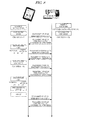
- FIG. 5 is a flowchart illustrating procedures when the sewing machine performs stitching in the stitchwork status checking system of the first embodiment of the present disclosure
- FIG. 6 is a flowchart illustrating a process when the sewing machine receives a command from the stitchwork status checking apparatus in the stitchwork status checking system of the first embodiment of the present disclosure
- FIG. 7 is a flowchart illustrating procedures of a monitoring process by the stitchwork status checking apparatus in the stitchwork status checking system of the first embodiment of the present disclosure
- FIG. 8 is a sequence diagram when the stitchwork status by the sewing machine is checked in the stitchwork status checking system of the first embodiment of the present disclosure
- FIG. 9 is a sequence diagram when the stitchwork status by the sewing machine is checked in the stitchwork status checking system of the first embodiment of the present disclosure.
- FIG. 10 is a block diagram illustrating conversion scheme of stitchwork data between the sewing machine and the stitchwork status checking apparatus in the stitchwork status checking system according to another embodiment of the present disclosure.
- FIG. 11 is a diagram illustrating an example display of the stitchwork status checking apparatus according to another embodiment of the present disclosure.
- FIGS. 1 to 4 A detailed explanation will be given of a stitchwork status checking system according to an embodiment of the present disclosure with reference to FIGS. 1 to 4 .
- the explanation for a duplicated portion with the same reference numeral in respective figures will be omitted.
- a stitchwork status checking system 1 includes a sewing machine 2 and a stitchwork status checking apparatus 3 .
- the sewing machine 2 and the stitchwork status checking apparatus 3 are connected with each other via a wireless network N.
- the sewing machine 2 and the stitchwork status checking apparatus 3 exchange following signals and data.
- the request signals or data of (1) to (4) are exchanged between the sewing machine 2 and the stitchwork status checking apparatus 3 .
- the status data of (2) and the stitchwork data of (4) are exchanged through different communication protocols. That is, the status data of (2) is transmitted through a transmission protocol that can transmit data to a transmission destination within a short time.
- the stitchwork data of (4) is transmitted through a transmission protocol that can transmit data to the transmission destination precisely. According to this embodiment, an explanation will be given of an example case in which the status data of (2) is exchanged through a UDP communication protocol, while the stitchwork data of (4) is exchanged through a TCP communication protocol.
- the sewing machine 2 is capable of stitching by performing a stitchwork based on stitchwork data input by a user, and is connected with the stitchwork status checking apparatus 3 via the wireless communication network N.
- the sewing machine 2 includes an input unit 4 , a display 5 , a stitchwork data selector unit 6 , a memory 7 , an external memory 8 , a temporal memory 9 , a CRC data converter unit 10 , a status information generator unit 11 , a stitch number counter unit 14 , a command receiver unit 15 , a command determiner unit 16 , a TCP transmitter unit 17 , and a UDP transmitter unit 18 .
- the input unit 4 is to allow the user to input, for example, an operation request to the sewing machine 2 and a setting of the stitchwork data.
- the input unit 4 includes input devices, such as a mouse, a touch screen (including one installed in the display 5 ), and a keyboard.
- the display 5 is to display screens for letting the user check, for example, the operation detail of the sewing machine 2 , and the stitchwork data.
- the display 5 can be a display device, such as an LCD or a CRT.
- the display 5 displays candidate patterns when a stitching is performed.
- the stitchwork data selector unit 6 selects stitchwork data corresponding to a pattern selected by the user and to be stitched.
- the stitchwork data selector unit 6 can refer to the contents of the memory 7 in the sewing machine 2 and the external memory 8 .
- the memory 7 is a so-called ROM, and can be used as a non-volatile memory. This memory 7 stores the stitchwork data.
- the external memory 8 is, for example, a USB having a memory area therein, and stores the stitchwork data in the memory area.
- the stitchwork data stored in the memory 7 and the external memory 8 is necessary data for the sewing machine 2 to perform stitching, and includes pieces of information on a pattern to be stitched, the size of the pattern, the number of stitches necessary to complete the pattern, the color to be applied, and a timing of the thread change.
- the stitchwork data is data with a size of substantially several hundred kilo bytes.
- the stitchwork data selector unit 6 displays on the display 5 patterns based on stitchwork data stored in the memory 7 or the external memory 8 .
- the user operates the input unit 4 , and selects a desired pattern among the patterns displayed on the display 5 .
- the stitchwork data selector unit 6 outputs the stitchwork data of the pattern selected by the user to the temporal memory 9 .
- the temporal memory 9 stores, as selected stitchwork data, the stitchwork data selected by the stitchwork data selector unit 6 .
- the temporal memory 9 is a so-called RAM, and can be used as a so-called volatile memory.
- the CRC data converter unit 10 converts the selected stitchwork data stored in the temporal memory 9 into CRC codes.
- the conversion of the CRC codes is performed by outputting the bit sequence of the selected stitchwork data as, for example, the values of 16-bit integers.
- the CRC codes always the same CRC codes are generated from the same selected stitchwork data. Hence, when even a 1 byte differs between the two selected stitchwork data, completely different codes as the CRC codes are generated.
- the converted CRC data by the CRC data converter unit 10 is stored in the temporal memory 9 as CRC data corresponding to the selected stitchwork data.
- the status information generator unit 11 generates status data containing the CRC data stored in the temporal memory 9 and the number of stitches performed by the sewing machine 2 with respect to the currently stitching pattern.
- the status data contains the selected stitchwork data and stitch number data.
- the status data is data with a size of substantially 10 bytes.
- the status information generator unit 11 includes a CRC data obtainer unit 12 and a stitch number data obtainer unit 13 .
- the CRC data obtainer unit 12 obtains the CRC data stored in the temporal memory 9 .
- the stitch number data obtainer unit 13 is connected with the stitch number counter unit 14 , and obtains, as the stitch number data, the number of stitches counted by the stitch number counter unit 14 .
- the stitch number counter unit 14 counts the number of stitches performed until the stitch number data is obtained after the sewing machine 2 starts stitching.
- the stitch number counter unit 14 is disposed so as to be connected with a motor that moves a needle up and down, and counts the number of stitches performed based on the rotation of the motor.
- the command receiver unit 15 receives a command transmitted from the stitchwork status checking apparatus 3 .
- the command transmitted from the stitchwork status checking apparatus 3 contains the status request signal and the stitchwork data request signal.
- the command receiver unit 15 always stands by in a status receivable of a command while the sewing machine 2 is in operation.
- the command determiner unit 16 determines whether the command received by the command receiver unit 15 is the “stitchwork data request signal” or the “status data request signal”. In the case of the “stitchwork data request signal”, the command determiner unit 16 transmits, to the TCP transmitter unit 17 , a transmission instruction of the “stitchwork data”. In the case of the “status data request signal”, the command determiner unit 16 transmits, to the UDP transmitter unit 18 , a transmission instruction of the “status data”.
- the TCP transmitter unit 17 performs a TCP transmission with a TCP receiver unit 29 of the stitchwork status checking apparatus 3 to be discussed later via the wireless network N.
- the TCP transmitter unit 17 reads the “selected stitchwork data” stored in the temporal memory 9 based on the transmission instruction of the “stitchwork data” from the command determiner unit 16 , and transmits the read data through a TCP communication.
- the TCP transmission is a communication protocol that establishes a connection prior to the communication and builds up a virtual communication line between the terminals performing the communication before the data transmission.
- a retransmission process is performed in this protocol, and it is guaranteed that the transmitted data is surely delivered and the pieces of the transmitted data are delivered in the transmission order. Hence, the transmission reliability is high.
- the UDP transmitter unit 18 performs a UDP transmission with a UDP receiver unit 31 of the stitchwork status checking apparatus 3 to be discussed later via the wireless network N.
- the UDP transmitter unit 18 reads the “status data” generated by the status information generator unit 11 based on the transmission instruction of the “status data” from the command determiner unit 16 , and transmits the read data through a UDP communication.
- This UDP transmission is based on a very simple protocol, the transmission is performed only once and no retransmission is performed, and thus it is not guaranteed that the transmitted data is surely delivered to the communication party. There is a possibility that the data is lost in the halfway, but it is a communication protocol applied when necessary to increase the transmission speed.
- This UDP transmission is advantageous when it is desired to transmit data in a real-time manner.
- the stitchwork status checking apparatus 3 transmits, to the sewing machine 2 , a command that is the “stitchwork data request signal” or the “status data request signal”. Moreover, the stitchwork status checking apparatus 3 receives the “stitchwork data” or the “status data” transmitted from the sewing machine 2 in response to such a command. The stitchwork status checking apparatus 3 draws the stitchwork status by the sewing machine 2 on a display 35 based on the received data.
- An example stitchwork status checking apparatus 3 is a general-purpose portable information terminal PDA (Personal Digital Assistant). As illustrated in FIG.
- the stitchwork status checking apparatus 3 includes a monitoring carry-out determiner unit 20 , a CRC data clear unit 21 , a temporal memory 22 , a command request unit 23 , a CRC data comparator unit 26 , a status information checker unit 27 , a command transmitter unit 28 , a TCP receiver unit 29 , a CRC data converter unit 30 , a UDP receiver unit 31 , a drawer unit 34 , and the display 35 .
- the temporal memory 22 stores the selected stitchwork data and the CRC data.
- the monitoring carry-out determiner unit 20 determines, by the stitchwork status checking apparatus 3 , the start of the monitoring of the stitching by the sewing machine 2 . With respect to the start of the monitoring, when the power switch of the stitchwork status checking apparatus 3 is turned ON, when a monitoring application in the stitchwork status checking apparatus 3 is activated, and when a “synchronization” button in the monitoring application is depressed, it is determined that the monitoring starts.
- the CRC data clear unit 21 erases the CRC data stored in the temporal memory 22 when the monitoring carry-out determiner unit 20 determines that the monitoring starts.
- the command request unit 23 outputs a signal of requesting the stitchwork data or the status data to the sewing machine 2 .
- the command request can be performed at an arbitrary cycle. The shorter the command request cycle is, the finer the stitching by the sewing machine 2 displayed on the stitchwork status checking apparatus 3 becomes. For example, the command request is performed for each 0.5 seconds.
- the command request unit 23 includes a status data request unit 24 and a stitchwork data request unit 25 .
- the status data request unit 24 requests the “status data” in the following conditions of (1) and (2).
- the stitchwork data request unit 25 requests the “stitchwork data” when a comparison result that the CRC data stored in the temporal memory 22 is different from the CRC data checked by the status information checker unit 27 is input from the CRC data comparator unit 26 to the command request unit 23 .
- the command transmitter unit 28 transmits, to the sewing machine 2 , the signal of the “stitchwork data request” or the “status information request” from the command request unit 23 .
- the command transmitter unit 28 transmits a command when the command request unit 23 requests a command.
- the TCP receiver unit 29 receives the “selected stitchwork data” transmitted by the TCP transmitter unit 17 of the sewing machine 2 through the TCP communication. This “selected stitchwork data” is stored in the temporal memory 22 of the stitchwork status checking apparatus 3 .
- the CRC data converter unit 30 converts the selected stitchwork data stored in the temporal memory 22 into the CRC codes like the CRC data converter unit 10 of the sewing machine 2 .
- the CRC codes converted by the CRC data converter unit 30 are stored in the temporal memory 22 as the CRC data corresponding to the selected stitchwork data.
- the UDP receiver unit 31 receives the “status data” transmitted by the UDP transmitter unit 18 of the sewing machine 2 through the UDP communication.
- the status information checker unit 27 includes a CRC data checker unit 32 that reads the “status data” received by the UDP receiver unit 31 , and extracts the “CRC data” contained in the “status data”, thereby checking the “CRC data”, and a stitch number data checker unit 33 that extracts the “stitch number data” to check the “stitch number data”.
- the CRC data comparator unit 26 compares the CRC data stored in the temporal memory 22 with the CRC data checked by the status information checker unit 27 .
- the comparison result is output to the command request unit 23 .
- the drawer unit 34 draws image data to be displayed on the display 35 based on the “selected stitchwork data” stored in the temporal memory 22 , and the “stitch number data” checked by the stitch number data checker unit 33 of the status information checker unit 27 .
- the drawer unit 34 includes a stitchwork data drawer unit 36 , a drawing part determiner unit 37 , and a drawing speed setting unit 38 .
- the stitchwork data drawer unit 36 performs drawing based on the “selected stitchwork data” and the “stitch number data”.
- FIG. 4 is a diagram illustrating example image data displayed on the display 35 .
- the stitchwork data drawer unit 36 performs following drawing based on information contained in the “selected stitchwork data”.
- stitchwork data drawer unit 36 performs following drawing based on information contained in the “stitch number data”.
- the drawing part determiner unit 37 draws which part of the selected stitchwork data the sewing machine 2 is stitching based on the current “stitch number data” and the “selected stitchwork data”.
- the drawing speed setting unit 38 sets the drawing speed based on a difference in the “stitch number data”.
- the drawing speed setting unit 38 stores the “stitch number data” received last time, and calculates a difference from the “stitch number data” newly received.
- the drawing cycle for each stitching on the stitchwork status checking apparatus 3 changes in accordance with the rotation speed of the sewing machine 2 , and thus the foregoing difference can be calculated based on the number of stitches increasing within a certain time. For example, when the number of stitches is obtained for each 0.5 seconds, if the “stitch number data” increases by five stitches from the previously obtained time, drawing is performed at 0.1 seconds per a stitching.
- This system connects the sewing machine 2 and the stitchwork status checking apparatus 3 with each other via the wireless network N. Accordingly, the progress status of the stitching by the sewing machine can be monitored at a remote location from the sewing machine 2 through the display 35 of the stitchwork status checking apparatus 3 .
- the operation of the sewing machine 2 and that of the stitchwork status checking apparatus 3 both configuring the stitchwork status checking system 1 will be explained separately.
- FIG. 5 is a flowchart when the sewing machine 2 performs stitching.
- the user selects a desired stitchwork pattern (step 101 ).
- the desired stitchwork pattern can be selected by selecting one of the candidates displayed on the display 5 of the sewing machine 2 through the input unit 4 .
- the stitchwork data corresponding to the selected stitchwork pattern is stored in the temporal memory 9 as the selected stitchwork data.
- the CRC data converter unit 10 calculates the CRC codes of the selected stitchwork data, and stores the calculated CRC codes in the temporal memory 9 as the CRC data (step 102 ).
- step 103 the user depresses a stitchwork start button of the sewing machine 2 (step 103 : YES). Accordingly, the sewing machine 2 starts stitching based on the selected stitchwork data.
- the stitch number counter unit 14 counts the number of stitches from the beginning of the stitching during the stitching operation. With respect to the number of stitches, every time the stitch number counter unit 14 counts the number of stitches, the number of stitches stored in the memory of the stitch number counter unit 14 is updated (step 104 ). The counting of the number of stitches is continued until the end of the stitching operation.
- the sewing machine 2 ends stitching after performing the stitching until the completion of the selected stitchwork data.
- step 105 NO
- the user selects again a stitchwork pattern, and the sewing machine 2 stitches such a stitchwork pattern (steps 101 to 105 ).
- step 105 YES
- the sewing machine 2 terminates the stitching operation.
- FIG. 6 is a flowchart illustrating a process when the sewing machine 2 receives a command from the stitchwork status checking apparatus 3 .
- the sewing machine 2 communicates with the stitchwork status checking apparatus 3 via the wireless network N as an interruption process.
- the command receiver unit 15 of the sewing machine 2 receives a command transmitted from the stitchwork status checking apparatus 3 (step 111 ).
- the command determiner unit 16 determines whether the received command is the command of “stitchwork data request” or the command of “status information request” (step 112 ).
- the UDP transmitter unit 18 transmits the status data generated by the status information generator unit 11 to the UDP receiver unit 31 of the stitchwork status checking apparatus 3 (step 113 ).
- This status data contains the CRC data obtained by converting the selected stitchwork data currently stitched into CRC codes, and the current number of stitches.
- the TCP transmitter unit 17 transmits the selected stitchwork data stored in the temporal memory 9 and currently stitched to the TCP receiver unit 29 of the stitchwork status checking apparatus 3 as the stitchwork data (step 114 ).
- the sewing machine 2 accepts this interruption process until the stitching completes or until the power is turned OFF.
- a new interruption process is accepted, the following steps are repeated after the step of receiving a command (step 111 ).
- FIG. 7 is a flowchart when the stitchwork status checking apparatus 3 checks the stitchwork status.
- the user checks the stitchwork status of the sewing machine 2 through the stitchwork status checking apparatus 3
- the user launches the stitchwork status checking application installed in the stitchwork status checking apparatus 3 .
- the CRC data clear unit 21 erases the CRC data stored in the temporal memory 22 (step 131 ).
- a request of the status data on the pattern currently stitched is made to the sewing machine 2 (step 132 ).
- the request of the status data is output by the status data request unit 24 of the command request unit 23 , and is output to the sewing machine 2 through the command transmitter unit 28 .
- the CRC data comparator unit 26 compares the CRC data contained in the received status data with the CRC data stored in the temporal memory 22 of the stitchwork status checking apparatus 3 (step 134 ).
- the status data request unit 24 of the command request unit 23 requests the stitchwork data currently stitched (step 135 ).
- Example cases in which the CRC data in the status data received from the sewing machine 2 is inconsistent with the CRC data stored in the temporal memory 22 are when the CRC data in the temporal memory 22 is erased at the beginning of the monitoring, and when the sewing machine 2 changes the selected stitchwork data.
- the command transmitter unit 28 transmits the stitchwork data request
- a reply with the stitchwork data from the sewing machine 2 based on the stitchwork data request is waited (step 136 ).
- the TCP receiver unit 29 stores the received stitchwork data in the temporal memory 22 .
- the CRC data converter unit 30 calculates the CRC codes of the stored and selected stitchwork data, and stores the calculated CRC codes in the temporal memory 22 as CRC data (step 137 ).
- step 134 drawing is performed based on the stitch number data in the status data received from the sewing machine 2 and the selected stitchwork data stored in the temporal memory 22 .
- the drawing speed of this drawing is set based on a difference between the stitch number data in the status data received from the sewing machine 2 and the stitch number data in the status data received last time (step 138 ).
- the stitchwork status checking apparatus 3 inquires the current number of stitches of the sewing machine 2 for each 0.5 seconds. Hence, when a difference between the last and current numbers of stitching is five stitches, drawing is performed at a 0.1 seconds cycle for each stitching.
- the drawer unit 34 performs drawing at this drawing speed (step 139 ).
- step 140 NO.
- the steps 132 , 133 , 134 , 138 , 139 , and 140 are repeated for each 0.5 seconds.
- a graphic display of the stitching synchronized with the actual stitching by the sewing machine can be expressed on the stitchwork status checking apparatus 3 .
- FIG. 8 is a sequence diagram when the stitchwork status checking apparatus 3 checks the stitchwork status of the sewing machine 2 in the stitchwork status checking system 1 .
- the user selects a pattern.
- pattern data that is “flower 001”
- the pattern data “flower 001” is stored in the temporal memory 9 as the selected pattern data.
- CRC codes “D1” calculated from the pattern data “flower 001” are stored in the temporal memory 9 as the CRC data.
- the stitchwork status checking application installed in the stitchwork status checking apparatus 3 is launched. Hence, the monitoring process is started.
- the stitchwork status checking apparatus 3 transmits a command of requesting the status data to the sewing machine 2 .
- the sewing machine 2 receives this command, and replies the current status data.
- This status data contains the CRC data “D1”.
- the stitchwork status checking apparatus 3 receives the status data containing that CRC data, and compares such CRC data with the CRC data stored in the local memory. As a result, since the CRC data at the sewing-machine end is “D1” but the CRC data at the stitchwork-status-checking-apparatus- 3 end is “0”, it is determined that the CRC data is “inconsistent”.
- the stitchwork status checking apparatus 3 transmits a command of requesting the selected stitchwork data to the sewing machine 2 based on the CRC data comparison result that is “inconsistent”.
- the sewing machine 2 receives this command, and replies the current selected stitchwork data.
- This selected stitchwork data is “flower 001”.
- the stitchwork status checking apparatus 3 receives this selected stitchwork data, and stores the received data in the temporal memory. Simultaneously, the stitchwork status checking apparatus 3 calculates the CRC codes from the pattern data “flower 001”. When the communication is carried out normally, the CRC code should be D1, and “D1” is stored as the CRC data.
- the stitchwork status checking apparatus 3 again transmits a command of requesting the status data, and the sewing machine 2 again replies the status data.
- the stitchwork status checking apparatus 3 compares the CRC data in the status data from the sewing machine 2 with the CRC data “D1” stored in the local memory. As a result, since the CRC data at the sewing-machine- 2 end is “D1” and the CRC data at the stitchwork-status-checking-apparatus- 3 end is also “D1”, it is determined that the CRC data is “consistent”.
- the stitchwork status checking apparatus 3 When it is determined that the CRC data is “consistent”, the stitchwork status checking apparatus 3 performs drawing based on the received and selected stitchwork data “flower 001” and the number of stitches contained in the status data.
- FIG. 9 is a sequence diagram when the stitchwork status checking apparatus 3 checks the stitchwork status by the sewing machine 2 when the selected pattern data is changed from “flower 001” to “ocean 020” at the sewing machine 2 in the stitchwork status checking system 1 .
- the selected pattern data “flower 001” and the CRC data “D1” thereof are stored in the sewing machine 2 .
- the stitchwork status checking apparatus 3 the selected pattern data “flower 001” and the CRC data “D1” are also stored. Transmission of the request command of the status data and reply with the status data based on the former request are performed between the sewing machine 2 and the stitchwork status checking apparatus 3 .
- the stitchwork status checking apparatus 3 performs drawing on the display 35 based on the selected pattern data “flower 001” and the “number of stitches” in the received status data.
- the sewing machine 2 When receiving a command of requesting the status data from the stitchwork status checking apparatus 3 , the sewing machine 2 replies the status data containing the CRC data “D2”.
- the stitchwork status checking apparatus 3 receives the status data containing such CRC data, and compares this CRC data with the CRC data stored in the local memory. As a result, since the CRC data at the sewing-machine- 2 end is “D2” and the CRC data at the stitchwork-status-checking-apparatus- 3 end is “D1”, it is determined that the CRC data is “inconsistent”.
- the stitchwork status checking apparatus 3 transmits a command of requesting the selected stitchwork data to the sewing machine 2 .
- the sewing machine 2 receives this command, and replies the current selected stitchwork data.
- This selected stitchwork data is “ocean 020”.
- the stitchwork status checking apparatus 3 receives this selected stitchwork data, and stores such data in the temporal memory 22 . Simultaneously, the stitchwork status checking apparatus 3 calculates the CRC codes from the pattern data “ocean 020”. When the communication is carried out normally, the CRC codes should be D2 and “D2” is stored as the CRC data.
- the stitchwork status checking apparatus 3 compares the CRC data in the status data from the sewing machine 2 with the CRC data stored in the local memory. As a result, since the CRC data at the sewing-machine- 2 end is “D2” and the CRC data at the stitchwork-status-checking-apparatus- 3 end is “D2”, it is determined that the CRC data is “consistent”.
- the stitchwork status checking apparatus 3 When it is determined that the CRC data is “consistent”, the stitchwork status checking apparatus 3 performs drawing based on the received and selected pattern data “ocean 020” and the number of stitches in the status data.
- the stitchwork status checking system 1 of the above-explained embodiment accomplishes the following advantages.
- the selected stitchwork data is stored in both of the temporal memory 9 of the sewing machine 2 and the temporal memory 22 of the stitchwork status checking apparatus 3 .
- the CRC codes calculated from the selected stitchwork data are compared with each other. This reduces the data quantity exchanged between the sewing machine 2 and the stitchwork status checking apparatus 3 .
- the stitchwork status checking apparatus 3 can recognize that the pattern is changed since the codes are inconsistent with each other.
- the stitchwork status checking apparatus 3 requests the pattern data currently stitched by the sewing machine 2 , and receives such data from the sewing machine 2 .
- the data communication in this case is carried out through the TCP protocol, and thus the stitchwork data is surely delivered to the stitchwork status checking apparatus 3 without any error.
- the TCP protocol lacks the real-time characteristics, but can correctly transfer data. Accordingly, the data in the stitchwork status checking apparatus 3 is replaced with the data in the sewing machine 2 , and thus the same pattern is displayed on the stitchwork status checking apparatus 3 .
- a communication is carried out between the sewing machine 2 and the stitchwork status checking apparatus 3 via the wireless network N, enabling the user to check the stitchwork status of the sewing machine 2 through the stitchwork status checking apparatus 3 . It is possible for the user to not only monitor the stitchwork status near the sewing machine 2 but also carry the stitchwork status checking apparatus 3 and go outside the communication range. When the communication is enabled again, the monitoring is immediately restarted, and thus a stitch drawing can be recovered correctly.
- the TCP protocol needs a relatively large data transmission (several hundred kilobytes or so), but a transmission is performed while confirming whether the data is delivered to the communication counterparty, and thus a precise transmission is enabled. Accordingly, the stitchwork data is transmitted through the TCP protocol.
- the UDP protocol enables a communication through a relatively little data transmission (several ten bytes or so). During the monitoring, a transmission of several ten bytes is performed at a cycle of several hundred milliseconds, and thus the communication data quantity can be suppressed extremely little.
- this packet is discarded, and a next data reception is awaited. That is, even if the communication is interrupted, the communication is not particularly terminated upon an error detection, a recovery to a normal communication is awaited, and when the normal communication is enabled again, a drawing process is restarted. That is, even if the communication is interrupted, it is easy to recover the communication once the normal communication is enabled again.
- the stitching is graphically drawn on the stitchwork status checking apparatus 3 at a remote location.
- the actual stitching is synchronized with the graphic drawing.
- the drawing is performed at a fast speed, and in the case of the slow stitching, the drawing is performed slowly. Accordingly, even if the user is apart from the sewing machine 2 , it is possible for the user to easily grasp how the stitching is performed.
- the communication environment may become poor due to a radio wave intensity, a communication distance, and an obstacle like a wall.
- the communication may be interrupted temporarily.
- the location is changed, or when the direction of the stitchwork status checking apparatus 3 is changed, the communication may be recovered frequently. While the communication is interrupted, the drawing by the stitchwork status checking apparatus 3 is interrupted, but when the communication is recovered, drawing is restarted up to the actual stitchwork status, and thus a synchronization between the sewing machine 2 and the stitchwork status checking apparatus 3 is established.
- the CRC codes are calculated from the selected stitchwork data stored in the temporal memory of the sewing machine 2 and the temporal memory of the stitchwork status checking apparatus 3 , and the calculated CRC codes are utilized as the CRC data.
- the pattern data may be converted in other data than the CRC data as long as such data is unique to the pattern data and has a smaller quantity than that of the pattern data.
- code converter units 41 that convert codes through the same scheme are provided for the respective temporal memories of the sewing machine 2 and the stitchwork status checking apparatus 3 .
- the code converter units 41 convert the pattern data into unique codes with a small quantity.
- the converted unique codes are stored in the respective temporal memories.
- the stitchwork data when the stitchwork data is converted into unique codes, in addition to the conversion of the whole stitchwork data, the stitchwork data may be divided based on various references, and a piece may be converted into unique codes.
- the “selected stitchwork data” and the “status data” are transmitted from the sewing machine 2 to the stitchwork status checking apparatus 3 through the TCP protocol and the UDP protocol, respectively, but the combination of the communication protocols is not limited to this example. That is, with respect to the “selected stitchwork data”, communication protocols other than the TCP protocol are applicable as long as the data can be surely transmitted to the transmission destination. In addition, with respect to the “status data”, communication protocols other than the UDP protocol are applicable as long as the data can be transmitted to the transmission destination within a short time.
- the stitchwork status checking apparatus 3 may display, in addition to the stitchwork status by the sewing machine 2 , events like a thread replacement as illustrated in FIG. 11 .
- Example other events are snaggling of threads, and a deactivation of the sewing machine due to a thread break.
Landscapes
- Engineering & Computer Science (AREA)
- Textile Engineering (AREA)
- Computer Hardware Design (AREA)
- Microelectronics & Electronic Packaging (AREA)
- Physics & Mathematics (AREA)
- Probability & Statistics with Applications (AREA)
- Theoretical Computer Science (AREA)
- Mechanical Engineering (AREA)
- Sewing Machines And Sewing (AREA)
- Automatic Embroidering For Embroidered Or Tufted Products (AREA)
Abstract
Description
Claims (6)
Applications Claiming Priority (2)
| Application Number | Priority Date | Filing Date | Title |
|---|---|---|---|
| JP2013-165556 | 2013-08-08 | ||
| JP2013165556A JP6265650B2 (en) | 2013-08-08 | 2013-08-08 | Embroidery status confirmation system, embroidery status confirmation device, embroidery status confirmation method, and embroidery status confirmation program |
Publications (2)
| Publication Number | Publication Date |
|---|---|
| US20150040810A1 US20150040810A1 (en) | 2015-02-12 |
| US9458560B2 true US9458560B2 (en) | 2016-10-04 |
Family
ID=49876505
Family Applications (1)
| Application Number | Title | Priority Date | Filing Date |
|---|---|---|---|
| US14/140,946 Active 2035-02-04 US9458560B2 (en) | 2013-08-08 | 2013-12-26 | Stitchwork status checking system, stitchwork status checking apparatus, stitchwork status checking method and stitchwork status checking program |
Country Status (4)
| Country | Link |
|---|---|
| US (1) | US9458560B2 (en) |
| EP (1) | EP2835464B1 (en) |
| JP (1) | JP6265650B2 (en) |
| CN (1) | CN104345710B (en) |
Families Citing this family (8)
| Publication number | Priority date | Publication date | Assignee | Title |
|---|---|---|---|---|
| WO2016019283A1 (en) * | 2014-08-01 | 2016-02-04 | Universal Instruments Corporation | Sewing machine, system and method |
| US10021550B2 (en) * | 2015-05-04 | 2018-07-10 | L&P Property Management Company | Wireless bedding machine control system |
| EP3325705A1 (en) * | 2015-07-21 | 2018-05-30 | Twine Solutions Ltd. | An integrated system and method for treating a thread and using thereof |
| JP2018176214A (en) * | 2017-04-11 | 2018-11-15 | 蛇の目ミシン工業株式会社 | Electric press, control method and program |
| CN110258030A (en) * | 2019-07-03 | 2019-09-20 | 珞石(北京)科技有限公司 | A Cloth Sewing Speed Synchronization Method Based on Robot Control System |
| JP7472439B2 (en) * | 2019-07-26 | 2024-04-23 | ブラザー工業株式会社 | MONITORING SYSTEM, SEWING MACHINE, AND MONITORING METHOD |
| WO2021199253A1 (en) | 2020-03-31 | 2021-10-07 | ブラザー工業株式会社 | Sewing machine and notification program |
| JP2024171843A (en) | 2023-05-30 | 2024-12-12 | ブラザー工業株式会社 | Sewing system, monitoring program, and sewing machine |
Citations (13)
| Publication number | Priority date | Publication date | Assignee | Title |
|---|---|---|---|---|
| JPH0564694A (en) | 1991-09-09 | 1993-03-19 | Brother Ind Ltd | Central control device for sewing machine |
| US5253599A (en) * | 1991-09-20 | 1993-10-19 | Aisin Seiki Kabushiki Kaisha | Embroidering system and control system therefor |
| US5921194A (en) | 1996-11-13 | 1999-07-13 | Brother Kogyo Kabushiki Kaisha | Sewing machine control device with display for displaying control information of sewing machines |
| US5978559A (en) * | 1997-10-07 | 1999-11-02 | Xerox Corporation | User interface for distributed printing system |
| US6216618B1 (en) * | 2000-04-07 | 2001-04-17 | Pulse Microsystems Ltd. | Embroidery system utilizing windows CE based GUI |
| US20010004717A1 (en) | 1999-12-16 | 2001-06-21 | Rui Zhang | Sewing apparatus management system |
| US6445970B1 (en) * | 2000-02-17 | 2002-09-03 | Melco Industries, Inc. | Computerized embroidery machine diagnostics |
| US20050060058A1 (en) | 2003-05-22 | 2005-03-17 | Marion Cameron | Embroidery network control system and method |
| US8175850B2 (en) * | 2008-11-26 | 2012-05-08 | General Electric Company | Monitoring system with dynamically configurable non-interfering signal processing |
| US8176861B2 (en) * | 2007-03-23 | 2012-05-15 | Brother Kogyo Kabushiki Kaisha | Embroidery data processor, sewing machine, and computer readable medium for embroidery data processing |
| US20120245727A1 (en) | 2011-03-23 | 2012-09-27 | Brother Kogyo Kabushiki Kaisha | Sewing machine system, sewing machine, and computer readable medium |
| US8813664B2 (en) * | 2009-11-25 | 2014-08-26 | Brother Kogyo Kabushiki Kaisha | Controller, computer readable medium storing control program, and sewing machine |
| US8972039B1 (en) * | 2013-08-08 | 2015-03-03 | Janome Sewing Machine Co., Ltd. | Stitchwork status checking system, stitchwork status checking apparatus, stitchwork status checking method and stitchwork status checking program |
Family Cites Families (5)
| Publication number | Priority date | Publication date | Assignee | Title |
|---|---|---|---|---|
| JP2000185184A (en) * | 1998-12-24 | 2000-07-04 | Brother Ind Ltd | sewing machine |
| JP2001017757A (en) * | 1999-07-05 | 2001-01-23 | Brother Ind Ltd | Embroidery sewing machine |
| JP2001170383A (en) * | 1999-12-16 | 2001-06-26 | Brother Ind Ltd | Embroidery equipment management system |
| CN201075174Y (en) * | 2007-08-28 | 2008-06-18 | 冯筠荪 | Computerized embroidering machine control apparatus |
| CN201459403U (en) * | 2009-06-26 | 2010-05-12 | 北京兴大豪科技开发有限公司 | Embroidery machine control device |
-
2013
- 2013-08-08 JP JP2013165556A patent/JP6265650B2/en active Active
- 2013-12-26 CN CN201310731511.6A patent/CN104345710B/en not_active Expired - Fee Related
- 2013-12-26 US US14/140,946 patent/US9458560B2/en active Active
- 2013-12-30 EP EP13199753.8A patent/EP2835464B1/en active Active
Patent Citations (13)
| Publication number | Priority date | Publication date | Assignee | Title |
|---|---|---|---|---|
| JPH0564694A (en) | 1991-09-09 | 1993-03-19 | Brother Ind Ltd | Central control device for sewing machine |
| US5253599A (en) * | 1991-09-20 | 1993-10-19 | Aisin Seiki Kabushiki Kaisha | Embroidering system and control system therefor |
| US5921194A (en) | 1996-11-13 | 1999-07-13 | Brother Kogyo Kabushiki Kaisha | Sewing machine control device with display for displaying control information of sewing machines |
| US5978559A (en) * | 1997-10-07 | 1999-11-02 | Xerox Corporation | User interface for distributed printing system |
| US20010004717A1 (en) | 1999-12-16 | 2001-06-21 | Rui Zhang | Sewing apparatus management system |
| US6445970B1 (en) * | 2000-02-17 | 2002-09-03 | Melco Industries, Inc. | Computerized embroidery machine diagnostics |
| US6216618B1 (en) * | 2000-04-07 | 2001-04-17 | Pulse Microsystems Ltd. | Embroidery system utilizing windows CE based GUI |
| US20050060058A1 (en) | 2003-05-22 | 2005-03-17 | Marion Cameron | Embroidery network control system and method |
| US8176861B2 (en) * | 2007-03-23 | 2012-05-15 | Brother Kogyo Kabushiki Kaisha | Embroidery data processor, sewing machine, and computer readable medium for embroidery data processing |
| US8175850B2 (en) * | 2008-11-26 | 2012-05-08 | General Electric Company | Monitoring system with dynamically configurable non-interfering signal processing |
| US8813664B2 (en) * | 2009-11-25 | 2014-08-26 | Brother Kogyo Kabushiki Kaisha | Controller, computer readable medium storing control program, and sewing machine |
| US20120245727A1 (en) | 2011-03-23 | 2012-09-27 | Brother Kogyo Kabushiki Kaisha | Sewing machine system, sewing machine, and computer readable medium |
| US8972039B1 (en) * | 2013-08-08 | 2015-03-03 | Janome Sewing Machine Co., Ltd. | Stitchwork status checking system, stitchwork status checking apparatus, stitchwork status checking method and stitchwork status checking program |
Non-Patent Citations (1)
| Title |
|---|
| European Search Report of corresponding EP21067905 application; Apr. 2, 2014; Munich, Germany. |
Also Published As
| Publication number | Publication date |
|---|---|
| JP2015033468A (en) | 2015-02-19 |
| EP2835464A1 (en) | 2015-02-11 |
| CN104345710A (en) | 2015-02-11 |
| JP6265650B2 (en) | 2018-01-24 |
| CN104345710B (en) | 2018-06-29 |
| US20150040810A1 (en) | 2015-02-12 |
| EP2835464B1 (en) | 2016-07-13 |
Similar Documents
| Publication | Publication Date | Title |
|---|---|---|
| US8972039B1 (en) | Stitchwork status checking system, stitchwork status checking apparatus, stitchwork status checking method and stitchwork status checking program | |
| US9458560B2 (en) | Stitchwork status checking system, stitchwork status checking apparatus, stitchwork status checking method and stitchwork status checking program | |
| JP6312877B2 (en) | Method, apparatus and system for intelligently controlling a device and plug and play device | |
| JP5789610B2 (en) | Communication apparatus and communication method | |
| US20220303746A1 (en) | Bluetooth connection method and apparatus, wearable device, and computer-readable storage medium | |
| US9813598B2 (en) | Light emitting system, light emission control apparatus and control method therefor, communication system and control method therefor and storage medium | |
| KR101842559B1 (en) | Terminal, server, and terminal control method | |
| CN112419693A (en) | Device control method, device, display device and computer readable storage medium | |
| CN109168145B (en) | Wireless pairing method and device for manual operator and mobile robot and manual operator | |
| CN110392412B (en) | Network distribution method, device, equipment and medium for Internet of things equipment | |
| CN105491428A (en) | Method and system for controlling smart TV | |
| US9600088B2 (en) | Method and apparatus for displaying a pointer on an external display | |
| CN113401801A (en) | System and method for remotely controlling a crane | |
| CN111866277A (en) | Electric quantity display method, device, equipment and storage medium of wireless earphone | |
| CN113849423B (en) | Data writing prompt method, electronic device, device and readable storage medium | |
| CN113225714A (en) | Screen projection method and system | |
| CN113347618A (en) | Bluetooth pairing method, device and system, Bluetooth intelligent terminal and storage medium | |
| US20240241781A1 (en) | Device control method and apparatus, electronic device and readable storage medium | |
| CN114095295B (en) | Intelligent doorbell information inheritance method, intelligent doorbell and computer readable storage medium | |
| WO2015163742A1 (en) | Device control method and apparatus in home network system | |
| CN105316874B (en) | Operation panel and sewing machine | |
| US20170220019A1 (en) | Plc maintenance support device and plc maintenance support program | |
| WO2013136702A1 (en) | Wireless communication apparatus, wireless communication method, and wireless communication control program | |
| KR20140101572A (en) | Method and apparatus for providing service quality information in an electronic device | |
| CN105163154A (en) | Method and system for controlling remote control, response method of control on remote control and terminal |
Legal Events
| Date | Code | Title | Description |
|---|---|---|---|
| AS | Assignment |
Owner name: JANOME SEWING MACHINE CO., LTD., JAPAN Free format text: ASSIGNMENT OF ASSIGNORS INTEREST;ASSIGNORS:KONGO, TAKESHI;HOSAKA, YUKIO;REEL/FRAME:031862/0611 Effective date: 20131125 |
|
| STCF | Information on status: patent grant |
Free format text: PATENTED CASE |
|
| FEPP | Fee payment procedure |
Free format text: PAYOR NUMBER ASSIGNED (ORIGINAL EVENT CODE: ASPN); ENTITY STATUS OF PATENT OWNER: LARGE ENTITY |
|
| MAFP | Maintenance fee payment |
Free format text: PAYMENT OF MAINTENANCE FEE, 4TH YEAR, LARGE ENTITY (ORIGINAL EVENT CODE: M1551); ENTITY STATUS OF PATENT OWNER: LARGE ENTITY Year of fee payment: 4 |
|
| AS | Assignment |
Owner name: JANOME CORPORATION, JAPAN Free format text: CHANGE OF NAME;ASSIGNOR:JANOME SEWING MACHINE CO., LTD.;REEL/FRAME:060613/0324 Effective date: 20211001 |
|
| MAFP | Maintenance fee payment |
Free format text: PAYMENT OF MAINTENANCE FEE, 8TH YEAR, LARGE ENTITY (ORIGINAL EVENT CODE: M1552); ENTITY STATUS OF PATENT OWNER: LARGE ENTITY Year of fee payment: 8 |