US9457828B1 - Utility cart - Google Patents
Utility cart Download PDFInfo
- Publication number
- US9457828B1 US9457828B1 US13/935,542 US201313935542A US9457828B1 US 9457828 B1 US9457828 B1 US 9457828B1 US 201313935542 A US201313935542 A US 201313935542A US 9457828 B1 US9457828 B1 US 9457828B1
- Authority
- US
- United States
- Prior art keywords
- compartment
- panel
- cart
- frame
- retainer
- Prior art date
- Legal status (The legal status is an assumption and is not a legal conclusion. Google has not performed a legal analysis and makes no representation as to the accuracy of the status listed.)
- Active
Links
- 238000000034 method Methods 0.000 description 5
- 238000012986 modification Methods 0.000 description 2
- 230000004048 modification Effects 0.000 description 2
- 230000000717 retained effect Effects 0.000 description 2
- 230000004075 alteration Effects 0.000 description 1
- 230000000712 assembly Effects 0.000 description 1
- 238000000429 assembly Methods 0.000 description 1
- 238000012423 maintenance Methods 0.000 description 1
- 238000005259 measurement Methods 0.000 description 1
- 230000007246 mechanism Effects 0.000 description 1
- 230000008439 repair process Effects 0.000 description 1
- 238000012360 testing method Methods 0.000 description 1
- 239000011800 void material Substances 0.000 description 1
Images


Classifications
-
- B—PERFORMING OPERATIONS; TRANSPORTING
- B62—LAND VEHICLES FOR TRAVELLING OTHERWISE THAN ON RAILS
- B62B—HAND-PROPELLED VEHICLES, e.g. HAND CARTS OR PERAMBULATORS; SLEDGES
- B62B5/00—Accessories or details specially adapted for hand carts
-
- B—PERFORMING OPERATIONS; TRANSPORTING
- B25—HAND TOOLS; PORTABLE POWER-DRIVEN TOOLS; MANIPULATORS
- B25H—WORKSHOP EQUIPMENT, e.g. FOR MARKING-OUT WORK; STORAGE MEANS FOR WORKSHOPS
- B25H3/00—Storage means or arrangements for workshops facilitating access to, or handling of, work tools or instruments
-
- B—PERFORMING OPERATIONS; TRANSPORTING
- B25—HAND TOOLS; PORTABLE POWER-DRIVEN TOOLS; MANIPULATORS
- B25B—TOOLS OR BENCH DEVICES NOT OTHERWISE PROVIDED FOR, FOR FASTENING, CONNECTING, DISENGAGING OR HOLDING
- B25B1/00—Vices
- B25B1/06—Arrangements for positively actuating jaws
- B25B1/10—Arrangements for positively actuating jaws using screws
- B25B1/103—Arrangements for positively actuating jaws using screws with one screw perpendicular to the jaw faces, e.g. a differential or telescopic screw
-
- B—PERFORMING OPERATIONS; TRANSPORTING
- B25—HAND TOOLS; PORTABLE POWER-DRIVEN TOOLS; MANIPULATORS
- B25B—TOOLS OR BENCH DEVICES NOT OTHERWISE PROVIDED FOR, FOR FASTENING, CONNECTING, DISENGAGING OR HOLDING
- B25B1/00—Vices
- B25B1/24—Details, e.g. jaws of special shape, slideways
- B25B1/2405—Construction of the jaws
- B25B1/241—Construction of the jaws characterised by surface features or material
-
- B—PERFORMING OPERATIONS; TRANSPORTING
- B25—HAND TOOLS; PORTABLE POWER-DRIVEN TOOLS; MANIPULATORS
- B25B—TOOLS OR BENCH DEVICES NOT OTHERWISE PROVIDED FOR, FOR FASTENING, CONNECTING, DISENGAGING OR HOLDING
- B25B5/00—Clamps
- B25B5/06—Arrangements for positively actuating jaws
- B25B5/10—Arrangements for positively actuating jaws using screws
-
- B—PERFORMING OPERATIONS; TRANSPORTING
- B25—HAND TOOLS; PORTABLE POWER-DRIVEN TOOLS; MANIPULATORS
- B25B—TOOLS OR BENCH DEVICES NOT OTHERWISE PROVIDED FOR, FOR FASTENING, CONNECTING, DISENGAGING OR HOLDING
- B25B5/00—Clamps
- B25B5/16—Details, e.g. jaws, jaw attachments
- B25B5/163—Jaws or jaw attachments
-
- B—PERFORMING OPERATIONS; TRANSPORTING
- B62—LAND VEHICLES FOR TRAVELLING OTHERWISE THAN ON RAILS
- B62B—HAND-PROPELLED VEHICLES, e.g. HAND CARTS OR PERAMBULATORS; SLEDGES
- B62B3/00—Hand carts having more than one axis carrying transport wheels; Steering devices therefor; Equipment therefor
- B62B3/002—Hand carts having more than one axis carrying transport wheels; Steering devices therefor; Equipment therefor characterised by a rectangular shape, involving sidewalls or racks
- B62B3/005—Details of storage means, e.g. drawers, bins or racks
-
- B—PERFORMING OPERATIONS; TRANSPORTING
- B62—LAND VEHICLES FOR TRAVELLING OTHERWISE THAN ON RAILS
- B62B—HAND-PROPELLED VEHICLES, e.g. HAND CARTS OR PERAMBULATORS; SLEDGES
- B62B3/00—Hand carts having more than one axis carrying transport wheels; Steering devices therefor; Equipment therefor
- B62B3/02—Hand carts having more than one axis carrying transport wheels; Steering devices therefor; Equipment therefor involving parts being adjustable, collapsible, attachable, detachable or convertible
-
- B—PERFORMING OPERATIONS; TRANSPORTING
- B62—LAND VEHICLES FOR TRAVELLING OTHERWISE THAN ON RAILS
- B62B—HAND-PROPELLED VEHICLES, e.g. HAND CARTS OR PERAMBULATORS; SLEDGES
- B62B3/00—Hand carts having more than one axis carrying transport wheels; Steering devices therefor; Equipment therefor
- B62B3/04—Hand carts having more than one axis carrying transport wheels; Steering devices therefor; Equipment therefor involving means for grappling or securing in place objects to be carried; Loading or unloading equipment
-
- B—PERFORMING OPERATIONS; TRANSPORTING
- B62—LAND VEHICLES FOR TRAVELLING OTHERWISE THAN ON RAILS
- B62B—HAND-PROPELLED VEHICLES, e.g. HAND CARTS OR PERAMBULATORS; SLEDGES
- B62B3/00—Hand carts having more than one axis carrying transport wheels; Steering devices therefor; Equipment therefor
- B62B3/10—Hand carts having more than one axis carrying transport wheels; Steering devices therefor; Equipment therefor characterised by supports specially adapted to objects of definite shape
- B62B3/106—Hand carts having more than one axis carrying transport wheels; Steering devices therefor; Equipment therefor characterised by supports specially adapted to objects of definite shape the objects being bags
Definitions
- the present application generally relates to devices and methods for storing and transporting collections of items. More specifically, the present application relates to a utility cart having certain advantageous features.
- Portable utility carts and cabinets are well known for storing and transporting a variety of items, such as audio/video equipment, tool sets and supplies for hotel service employees.
- Prior art utility carts are typically designed to carry either disparate items or an inflexible predefined set of specific items.
- a need therefore exists for a utility cart which can be reconfigured as desired to carry a defined set of items.
- an example utility cart comprising: a frame comprising a compartment base, a compartment back panel, a first compartment side panel, a compartment top retainer and a compartment side retainer; a plurality of wheels supporting the frame; and a door assembly hingedly attached to the frame.
- the door assembly comprises a compartment front panel, a compartment top panel, and a second compartment side panel.
- the compartment top panel is hingedly attached to the compartment front panel, and the compartment top panel is movable between a first position wherein the compartment top panel engages the compartment top retainer, and a second position wherein the compartment top panel does not engage the compartment top retainer.
- the door assembly is moveable between a closed position in which the second compartment side panel engages the compartment side retainer and an open position in which the second compartment side panel does not engage the compartment side retainer.
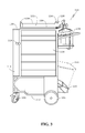
- FIG. 1 illustrates a right side view of an example utility cart.
- FIG. 2 illustrates a rear view of the example utility cart of FIG. 1 .
- FIG. 3 illustrates a left side view of the example utility cart of FIG. 1 .
- FIG. 4 illustrates the storage compartment of the example utility cart of FIG. 1 .
- FIG. 5 illustrates a left side view of the example utility cart of FIG. 1 .
- FIG. 6 illustrates a top perspective view of the example utility cart of FIG. 1 .
- FIG. 7 illustrates a top perspective view of the example utility cart of FIG. 1 .
- FIG. 8 illustrates a front left perspective view of the example utility cart of FIG. 1 .
- FIG. 9 illustrates a front left perspective view of the example utility cart of FIG. 1 .
- FIG. 10 illustrates a top left rear perspective view of the example utility cart of FIG. 1 .
- FIG. 11 illustrates a top left rear perspective view of the example utility cart of FIG. 1 .
- FIG. 12 illustrates a top right rear perspective view of the example utility cart of FIG. 1 .
- FIG. 13 illustrates a magnified perspective view of vice in closed position.
- FIG. 14 illustrates a magnified perspective view of vice in open position.
- FIGS. 1-14 illustrate various aspects of an example utility cart 100 .
- cart 100 comprises a frame 102 , at least one rear wheel 104 , at least one front wheel 106 , a handle 108 , a wastebasket retainer 110 , removable wastebasket 111 , a tool bag retainer or basket 112 , a drink holder 114 , and a removable tool bag 116 .
- FIG. 3 A left side view of cart 100 is shown in FIG. 3 .
- cart 100 further comprises a door assembly 118 which cooperates with compartment side retainer 119 and comprises compartment top panel 138 .
- Cart 100 also comprises a work surface 122 surrounded by fixed side walls 124 and hinged side wall 126 .
- hinged side wall 126 is disposed in an open or down position.
- Cart 100 comprises a vice 128 , plurality of drawers 130 , and a bi-level bottom 132 which accommodates differently sized front wheels 106 and rear wheels 104 .
- FIG. 4 further illustrates compartment base 133 which defines the bottom of a compartment that is formed when the door assembly is disposed in a closed position.
- FIG. 5 Another left side view of cart 100 is shown in FIG. 5 wherein the hinged side wall 126 is disposed in a closed or up position.
- the hinged side wall 126 When the hinged side wall 126 is in the closed position, as shown more clearly in FIG. 6 , items on work surface 122 are retained within the work surface.
- the hinged side wall 126 When the hinged side wall 126 is in the open position, as shown more clearly in FIG. 7 , items on work surface 122 are not so retained, and the hinged side wall 126 may function as an extension of the work surface 122 .
- FIG. 8 A front left perspective view of cart 100 is shown in FIG. 8 .
- cart 100 is configured such that door assembly 118 is disposed in a closed position.
- door assembly 118 cooperates with frame 102 to define the compartment.
- Door assembly 118 comprises compartment front panel 134 , a second compartment side panel 136 , and a compartment top panel 138 .
- Ladder hanger 140 is shown attached to door assembly 118 .
- FIG. 9 Another front left perspective view of cart 100 is shown in FIG. 9 .
- cart 100 is configured such that door assembly 118 is disposed in an open position.
- compartment top retainer 117 and the elements of frame 102 that define the compartment formed by door assembly 118 and frame 102 are visible.
- the elements of frame 102 that define the compartment include: the compartment base 133 , a first compartment side panel 135 , and a compartment back panel 137 .
- Removable storage panels 142 and 144 are disposed on the interior of door 118 and on cart 100 , respectively.
- Storage panels 142 and 144 may be secured to cart 100 using storage panel fasteners (not shown).
- the storage panel fasteners are hook and loop style fasteners, commonly referred to as Velcro.
- Velcro Velcro
- the storage panels 142 and 144 may be detached from the cart 100 and replaced with a substitute or alternate tool panel. This allows the cart 100 to be customized for specific applications, such as may be required by electrical contractors, hotel maintenance employees, computer repair personnel and plumbers, for example.
- Each storage panel may comprise holders, such as holder 146 , for retaining desired items within cart 100 .
- FIG. 11 provides another rear perspective view of cart 100 wherein tool bag 116 is disposed within basket 112 .
- tool bag 116 comprises a frame, a flexible covering comprising at least a portion of an outer surface of the tool bag, and a tool holder 150 .
- the tool holder 150 is hingedly attached to the frame, and the tool holder 150 is movable between a first position in which tool holder 150 may be folded downward, thereby reducing the lateral profile of the tool holder 150 (not shown), and a second position in which the lateral profile of the tool holder 150 is enlarged, as shown in FIG. 11 . In the second position, the tool holder 150 is configured to receive a handle of a tool.
- FIG. 12 provides an upper right rear perspective view of cart 100 wherein the tool bag 116 is covered by cover 148 . As illustrated, cover 148 may be locked using a standard lock 152
- Jaw 156 further comprises an indexing element 160 which mates with an indexing void defined by base 154 so as to properly orient the jaw 156 with respect to the base 154 .
- an indexing element 160 which mates with an indexing void defined by base 154 so as to properly orient the jaw 156 with respect to the base 154 .
Landscapes
- Engineering & Computer Science (AREA)
- Mechanical Engineering (AREA)
- Chemical & Material Sciences (AREA)
- Combustion & Propulsion (AREA)
- Transportation (AREA)
- Handcart (AREA)
Abstract
The utility cart of the present application comprises a frame, at least two wheels and a storage panel. In one embodiment, the storage panel is removable and capable of being replaced with an alternate storage panel.
Description
The present application generally relates to devices and methods for storing and transporting collections of items. More specifically, the present application relates to a utility cart having certain advantageous features.
Portable utility carts and cabinets are well known for storing and transporting a variety of items, such as audio/video equipment, tool sets and supplies for hotel service employees. Prior art utility carts are typically designed to carry either disparate items or an inflexible predefined set of specific items. A need therefore exists for a utility cart which can be reconfigured as desired to carry a defined set of items. Additionally, a need exists for a cart that securely carries a tool bag while providing visibility of items secured to the tool bag.
According to the present application, an example utility cart is disclosed. The example cart comprises: a frame comprising a compartment base, a compartment back panel, a first compartment side panel, a compartment top retainer and a compartment side retainer; a plurality of wheels supporting the frame; and a door assembly hingedly attached to the frame. The door assembly comprises a compartment front panel, a compartment top panel, and a second compartment side panel. The compartment top panel is hingedly attached to the compartment front panel, and the compartment top panel is movable between a first position wherein the compartment top panel engages the compartment top retainer, and a second position wherein the compartment top panel does not engage the compartment top retainer. The door assembly is moveable between a closed position in which the second compartment side panel engages the compartment side retainer and an open position in which the second compartment side panel does not engage the compartment side retainer.
The accompanying figures, which are incorporated in and constitute a part of the specification, illustrate various example apparatuses, systems, methods, and so on, and are used merely to illustrate various example embodiments. It should be noted that various components depicted in the figures may not be drawn to scale, and that the various assemblies and designs depicted in the figures are presented for purposes of illustration only, and should not be considered in any way as limiting.
The following reference characters identify the associated elements depicted in the drawings describing the present invention:
- 100 Cart
- 102 Frame
- 104 Rear Wheel
- 106 Front Wheel
- 108 Handle
- 110 Wastebasket Retainer
- 112 Basket
- 114 Drink Holder
- 116 Tool Bag
- 117 Compartment Top Retainer
- 118 Door Assembly
- 119 Compartment Side Retainer
- 122 Work Surface
- 124 Fixed Side Wall
- 126 Hinged Side Wall
- 128 Vice
- 130 Drawer
- 132 Bi-level Bottom
- 133 Compartment Base
- 134 Compartment Front Panel
- 135 First Compartment Side Panel
- 136 Second Compartment Side Panel
- 137 Compartment Back Panel
- 138 Compartment Top Panel
- 140 Ladder Hanger
- 142 Removable Storage Panel
- 144 Removable Storage Panel
- 146 Holder
- 147 Elongated Space
- 148 Cover
- 150 Tool Holder
- 152 Lock
A left side view of cart 100 is shown in FIG. 3 . As shown, cart 100 further comprises a door assembly 118 which cooperates with compartment side retainer 119 and comprises compartment top panel 138. Cart 100 also comprises a work surface 122 surrounded by fixed side walls 124 and hinged side wall 126. As shown, hinged side wall 126 is disposed in an open or down position. Cart 100 comprises a vice 128, plurality of drawers 130, and a bi-level bottom 132 which accommodates differently sized front wheels 106 and rear wheels 104.
The bi-level bottom 132 is more clearly shown in FIG. 4 . FIG. 4 further illustrates compartment base 133 which defines the bottom of a compartment that is formed when the door assembly is disposed in a closed position.
Another left side view of cart 100 is shown in FIG. 5 wherein the hinged side wall 126 is disposed in a closed or up position. When the hinged side wall 126 is in the closed position, as shown more clearly in FIG. 6 , items on work surface 122 are retained within the work surface. When the hinged side wall 126 is in the open position, as shown more clearly in FIG. 7 , items on work surface 122 are not so retained, and the hinged side wall 126 may function as an extension of the work surface 122.
A front left perspective view of cart 100 is shown in FIG. 8 . As shown, cart 100 is configured such that door assembly 118 is disposed in a closed position. When door assembly 118 is in the closed position, door assembly 118 cooperates with frame 102 to define the compartment. Door assembly 118 comprises compartment front panel 134, a second compartment side panel 136, and a compartment top panel 138. Ladder hanger 140 is shown attached to door assembly 118.
Another front left perspective view of cart 100 is shown in FIG. 9 . In FIG. 9 , cart 100 is configured such that door assembly 118 is disposed in an open position. As illustrated with door assembly 118 in the open position, compartment top retainer 117 and the elements of frame 102 that define the compartment formed by door assembly 118 and frame 102 are visible. The elements of frame 102 that define the compartment include: the compartment base 133, a first compartment side panel 135, and a compartment back panel 137. Removable storage panels 142 and 144 are disposed on the interior of door 118 and on cart 100, respectively. Storage panels 142 and 144 may be secured to cart 100 using storage panel fasteners (not shown). In the illustrated example embodiment, the storage panel fasteners are hook and loop style fasteners, commonly referred to as Velcro. Of course, one having ordinary skill in the art will recognize numerous alternate embodiments for storage panel fasteners.
The storage panels 142 and 144 may be detached from the cart 100 and replaced with a substitute or alternate tool panel. This allows the cart 100 to be customized for specific applications, such as may be required by electrical contractors, hotel maintenance employees, computer repair personnel and plumbers, for example. Each storage panel may comprise holders, such as holder 146, for retaining desired items within cart 100.
Referring now to FIG. 10 , a rear perspective view of cart 100 is presented. As shown in FIG. 10 , cart 100 is configured with hinged side wall 126 disposed in an open position such that it provides an extension for work surface 122. Further tool bag 116 has been removed from cart 100 providing a view of cover 148 and a more complete view of basket 112. Vice 128 is also illustrated in its closed configuration.
Notwithstanding that the numerical ranges and parameters setting forth the broad scope of the invention are approximations, the numerical values set forth in the specific examples are reported as precisely as possible. Any numerical value, however, inherently contains certain errors necessarily resulting from the standard deviation found in their respective testing measurements.
Furthermore, while the devices, systems, methods, and so on have been illustrated by describing examples, and while the examples have been described in considerable detail, it is not the intention of the applicant to restrict, or in any way, limit the scope of the appended claims to such detail. It is, of course, not possible to describe every conceivable combination of components or methodologies for purposes of describing the devices, systems, methods, and so on provided herein. Additional advantages and modifications will readily appear to those skilled in the art. Therefore, the invention, in its broader aspects, is not limited to the specific details and illustrative examples shown and described. Accordingly, departures may be made from such details without departing from the spirit or scope of the applicant's general inventive concept. Thus, this application is intended to embrace alterations, modifications, and variations that fall within the scope of the appended claims. The preceding description is not meant to limit the scope of the invention. Rather, the scope of the invention is to be determined by the appended claims and their equivalents.
Finally, to the extent that the term “includes” or “including” is employed in the detailed description or the claims, it is intended to be inclusive in a manner similar to the term “comprising,” as that term is interpreted when employed as a transitional word in a claim. Furthermore, to the extent that the term “or” is employed in the claims (e.g., A or B) it is intended to mean “A or B or both.” When the applicants intend to indicate “only A or B, but not both,” then the term “only A or B but not both” will be employed. Similarly, when the applicants intend to indicate “one and only one” of A, B, or C, the applicants will employ the phrase “one and only one.” Thus, use of the term “or” herein is the inclusive, and not the exclusive use. See Bryan A. Garner, A Dictionary of Modern Legal Usage 624 (2d. Ed. 1995).
Claims (10)
1. A cart comprising:
a frame, the frame comprising a compartment base, a compartment back panel, a first compartment side panel, a compartment top retainer and a compartment side retainer;
a plurality of wheels supporting the frame; and
a door assembly hingedly attached to the frame, the door assembly comprising:
a compartment front panel,
a compartment top panel, and
a second compartment side panel,
wherein the compartment top panel is hingedly attached to the compartment front panel, the compartment top panel being movable between a first position wherein the compartment top panel engages the compartment top retainer, and a second position wherein the compartment top panel does not engage the compartment top retainer; and
wherein the door assembly is moveable between a closed position in which the second compartment side panel engages the compartment side retainer and an open position in which the second compartment side panel does not engage the compartment side retainer.
2. The cart of claim 1 wherein the second compartment side panel is hingedly attached to the compartment front panel.
3. The cart of claim 1 further comprising at least one holder disposed within a compartment formed by the frame and the door assembly when the door assembly is in the closed position.
4. The cart of claim 1 wherein the frame defines an elongated vertical space for storing an item.
5. The cart of claim 1 wherein the frame comprises a bi-level base for accommodating wheels of different sizes.
6. The cart of claim 1 wherein the second compartment side panel is fixedly attached to the compartment front panel.
7. A cart comprising:
a frame, the frame comprising a compartment base, a compartment back panel, a first compartment side panel, a compartment top retainer and a compartment side retainer;
a plurality of wheels supporting the frame; and
a door assembly hingedly attached to the frame, the door assembly comprising:
a compartment front panel,
a compartment top panel hingedly attached to the compartment front panel, and
a second compartment side panel fixedly attached to the compartment front panel,
wherein the compartment top panel is movable between a first position wherein the compartment top panel engages the compartment top retainer, and a second position wherein the compartment top panel does not engage the compartment top retainer; and
wherein the door assembly is moveable between a closed position in which the second compartment side panel engages the compartment side retainer and an open position in which the second compartment side panel does not engage the compartment side retainer.
8. The cart of claim 7 further comprising at least one holder disposed within a compartment formed by the frame and the door assembly when the door assembly is in the closed position.
9. The cart of claim 7 wherein the frame defines an elongated vertical space for storing an item.
10. The cart of claim 7 wherein the frame comprises a bi-level base for accommodating wheels of different sizes.
Priority Applications (3)
| Application Number | Priority Date | Filing Date | Title |
|---|---|---|---|
| US13/935,542 US9457828B1 (en) | 2013-07-04 | 2013-07-04 | Utility cart |
| US14/824,949 US9849899B1 (en) | 2013-07-04 | 2015-08-12 | Utility cart |
| US14/824,959 US9862398B1 (en) | 2013-07-04 | 2015-08-12 | Utility cart |
Applications Claiming Priority (1)
| Application Number | Priority Date | Filing Date | Title |
|---|---|---|---|
| US13/935,542 US9457828B1 (en) | 2013-07-04 | 2013-07-04 | Utility cart |
Related Child Applications (2)
| Application Number | Title | Priority Date | Filing Date |
|---|---|---|---|
| US14/824,949 Division US9849899B1 (en) | 2013-07-04 | 2015-08-12 | Utility cart |
| US14/824,959 Division US9862398B1 (en) | 2013-07-04 | 2015-08-12 | Utility cart |
Publications (1)
| Publication Number | Publication Date |
|---|---|
| US9457828B1 true US9457828B1 (en) | 2016-10-04 |
Family
ID=56995096
Family Applications (3)
| Application Number | Title | Priority Date | Filing Date |
|---|---|---|---|
| US13/935,542 Active US9457828B1 (en) | 2013-07-04 | 2013-07-04 | Utility cart |
| US14/824,949 Active US9849899B1 (en) | 2013-07-04 | 2015-08-12 | Utility cart |
| US14/824,959 Expired - Fee Related US9862398B1 (en) | 2013-07-04 | 2015-08-12 | Utility cart |
Family Applications After (2)
| Application Number | Title | Priority Date | Filing Date |
|---|---|---|---|
| US14/824,949 Active US9849899B1 (en) | 2013-07-04 | 2015-08-12 | Utility cart |
| US14/824,959 Expired - Fee Related US9862398B1 (en) | 2013-07-04 | 2015-08-12 | Utility cart |
Country Status (1)
| Country | Link |
|---|---|
| US (3) | US9457828B1 (en) |
Cited By (14)
| Publication number | Priority date | Publication date | Assignee | Title |
|---|---|---|---|---|
| US20170080965A1 (en) * | 2003-09-19 | 2017-03-23 | Mobile-Shop Company, Llc | Tool Organizer |
| CN106553165A (en) * | 2016-10-09 | 2017-04-05 | 浙江陆虎汽车有限公司 | A kind of car door material prestowage dolly |
| CN108423054A (en) * | 2017-06-19 | 2018-08-21 | 汝州市中鼎科技有限公司 | A kind of meeting affairs trolley |
| US10239546B1 (en) * | 2016-10-03 | 2019-03-26 | Rella M. Scott | Folding utility cart |
| US10246116B2 (en) * | 2016-10-25 | 2019-04-02 | Rubbermaid Commercial Products Llc | Multipurpose utility carts |
| US20200205733A1 (en) * | 2013-09-26 | 2020-07-02 | I1 Sensortech, Inc. | Personal impact monitoring system |
| USD901175S1 (en) * | 2019-01-08 | 2020-11-10 | Edward G. Guirlinger | Tool cart |
| CN112429050A (en) * | 2020-11-27 | 2021-03-02 | 江苏盐西高新绿色产业发展有限公司 | Cleaning trolley |
| US20210347396A1 (en) * | 2020-05-05 | 2021-11-11 | Barmobile, LLC | Mobile serving device and method |
| US20220135099A1 (en) * | 2019-03-15 | 2022-05-05 | Covidien Lp | Cart for medical equipment |
| EP4249348A1 (en) | 2022-03-22 | 2023-09-27 | Österreichische Post AG | Delivery carriage |
| USD1018160S1 (en) * | 2023-07-11 | 2024-03-19 | Xi'an Dongyuemei Trading Co., Ltd. | Rotating storage caddy |
| US12077202B2 (en) | 2020-11-10 | 2024-09-03 | Milwaukee Electric Tool Corporation | Moveable storage and carrying device |
| US12466455B2 (en) | 2022-07-26 | 2025-11-11 | Milwaukee Electric Tool Corporation | Transportation device for units in modular system |
Families Citing this family (2)
| Publication number | Priority date | Publication date | Assignee | Title |
|---|---|---|---|---|
| US20190084602A1 (en) * | 2017-09-21 | 2019-03-21 | Geerpres, Inc. | Utility cart |
| US20240217569A1 (en) * | 2023-01-03 | 2024-07-04 | Claude A. Burnett, III | Horticulture Mobile Workstation |
Citations (12)
| Publication number | Priority date | Publication date | Assignee | Title |
|---|---|---|---|---|
| US2948798A (en) * | 1958-10-17 | 1960-08-09 | Nat Cornice Works | Mobile hot and cold food cart |
| US3520583A (en) * | 1967-12-14 | 1970-07-14 | John J Case | Tool cabinet |
| US20020109318A1 (en) * | 2001-02-09 | 2002-08-15 | Akro-Mils | Janitorial cart |
| US20040103598A1 (en) * | 2002-12-03 | 2004-06-03 | Marler Jon R. | Lockable wire enclosure and locking mechanism therefor |
| US6860494B1 (en) * | 2003-01-08 | 2005-03-01 | Karan L. Chisholm | Collapsible maintenance work cart system |
| US20060284391A1 (en) * | 2005-06-20 | 2006-12-21 | Sheehan Deirdre L | Trash cart |
| US20070267832A1 (en) * | 2006-05-16 | 2007-11-22 | Evgueni Denissov | Cleaning cart |
| US7338054B2 (en) * | 2005-04-18 | 2008-03-04 | Pint Eliana M | Self-contained utility cart |
| US7648149B2 (en) * | 2006-07-28 | 2010-01-19 | Chrysler Group Llc | Damped Rear Suspension Track Bar |
| US8157337B2 (en) * | 2009-06-16 | 2012-04-17 | Edwin Dizon Manalang | Tool box storage assembly |
| US20120119635A1 (en) * | 2007-09-05 | 2012-05-17 | Abel Gary V | Voter terminal storage and transport cart |
| US8419024B1 (en) * | 2009-08-14 | 2013-04-16 | Fernando Arroyo-Ferrer | Cleaning cart |
Family Cites Families (17)
| Publication number | Priority date | Publication date | Assignee | Title |
|---|---|---|---|---|
| US2615726A (en) * | 1947-02-07 | 1952-10-28 | Samuel G Brottman | Shopping cart |
| US2668977A (en) * | 1949-07-16 | 1954-02-16 | H F Woodward | Wheeled vacuum cleaner cart |
| US3494631A (en) * | 1968-01-29 | 1970-02-10 | Georgia Kreider | Cleaning equipment cart |
| US4966318A (en) * | 1989-03-10 | 1990-10-30 | Charlotte Dutka | Shopping organizer device |
| US5531366A (en) * | 1994-07-22 | 1996-07-02 | Strom; Grant C. | Carry out caddy for shopping carts |
| US6497423B1 (en) * | 1998-09-23 | 2002-12-24 | Rubbermaid Commercial Products Llc | Mobile maintenance cart having a storage compartment, a bag retention system, and a forward facing recess for supporting a container |
| US20050288571A1 (en) * | 2002-08-20 | 2005-12-29 | Welch Allyn, Inc. | Mobile medical workstation |
| AU2003243050A1 (en) * | 2003-04-21 | 2004-11-19 | Chong-Kuk Yi | Shopping bag |
| US8011484B2 (en) * | 2003-11-10 | 2011-09-06 | Mcintyre Lynne | Reconfigurable travel trunk |
| US20060097467A1 (en) * | 2004-11-08 | 2006-05-11 | Solvisions Technologies Int'l, Inc. | Shopping cart with shopping bag dispenser |
| CN101128353A (en) * | 2005-01-21 | 2008-02-20 | 勒博美商业产品有限责任公司 | maintenance car |
| US7887068B2 (en) * | 2006-10-17 | 2011-02-15 | Jeremy Ferguson | Mutually nestable shopping carts having bag hangers |
| AU2009200937A1 (en) * | 2008-03-10 | 2009-09-24 | Chermark Australia Pty Ltd | A Bag Having a Shopping Trolley Insert |
| GB0808858D0 (en) * | 2008-05-15 | 2008-06-25 | Young Ronald A | Combination of a trolley for carrying cleaning materials and bucket structure |
| WO2010065509A2 (en) * | 2008-12-01 | 2010-06-10 | Nadia Shalaby | Versatile, collapsible cart-trailer with modular components |
| US8162331B2 (en) * | 2009-02-02 | 2012-04-24 | Target Brands, Inc. | Utility cart assembly |
| US20120161408A1 (en) * | 2010-12-22 | 2012-06-28 | Guravtar Sidhu | Baby Carry On |
-
2013
- 2013-07-04 US US13/935,542 patent/US9457828B1/en active Active
-
2015
- 2015-08-12 US US14/824,949 patent/US9849899B1/en active Active
- 2015-08-12 US US14/824,959 patent/US9862398B1/en not_active Expired - Fee Related
Patent Citations (13)
| Publication number | Priority date | Publication date | Assignee | Title |
|---|---|---|---|---|
| US2948798A (en) * | 1958-10-17 | 1960-08-09 | Nat Cornice Works | Mobile hot and cold food cart |
| US3520583A (en) * | 1967-12-14 | 1970-07-14 | John J Case | Tool cabinet |
| US20020109318A1 (en) * | 2001-02-09 | 2002-08-15 | Akro-Mils | Janitorial cart |
| US20040103598A1 (en) * | 2002-12-03 | 2004-06-03 | Marler Jon R. | Lockable wire enclosure and locking mechanism therefor |
| US6860494B1 (en) * | 2003-01-08 | 2005-03-01 | Karan L. Chisholm | Collapsible maintenance work cart system |
| US7338054B2 (en) * | 2005-04-18 | 2008-03-04 | Pint Eliana M | Self-contained utility cart |
| US7232136B2 (en) * | 2005-06-20 | 2007-06-19 | Ebabe, Inc. | Trash cart |
| US20060284391A1 (en) * | 2005-06-20 | 2006-12-21 | Sheehan Deirdre L | Trash cart |
| US20070267832A1 (en) * | 2006-05-16 | 2007-11-22 | Evgueni Denissov | Cleaning cart |
| US7648149B2 (en) * | 2006-07-28 | 2010-01-19 | Chrysler Group Llc | Damped Rear Suspension Track Bar |
| US20120119635A1 (en) * | 2007-09-05 | 2012-05-17 | Abel Gary V | Voter terminal storage and transport cart |
| US8157337B2 (en) * | 2009-06-16 | 2012-04-17 | Edwin Dizon Manalang | Tool box storage assembly |
| US8419024B1 (en) * | 2009-08-14 | 2013-04-16 | Fernando Arroyo-Ferrer | Cleaning cart |
Cited By (22)
| Publication number | Priority date | Publication date | Assignee | Title |
|---|---|---|---|---|
| US10661818B2 (en) * | 2003-09-19 | 2020-05-26 | Mobile-Shop Company, Llc | Tool organizer |
| US20170080965A1 (en) * | 2003-09-19 | 2017-03-23 | Mobile-Shop Company, Llc | Tool Organizer |
| US20200205733A1 (en) * | 2013-09-26 | 2020-07-02 | I1 Sensortech, Inc. | Personal impact monitoring system |
| US11701058B2 (en) * | 2013-09-26 | 2023-07-18 | I1 Sensortech, Inc. | Personal impact monitoring system |
| US10239546B1 (en) * | 2016-10-03 | 2019-03-26 | Rella M. Scott | Folding utility cart |
| CN106553165A (en) * | 2016-10-09 | 2017-04-05 | 浙江陆虎汽车有限公司 | A kind of car door material prestowage dolly |
| CN106553165B (en) * | 2016-10-09 | 2019-05-14 | 浙江陆虎汽车有限公司 | A kind of car door material prestowage trolley |
| US10246116B2 (en) * | 2016-10-25 | 2019-04-02 | Rubbermaid Commercial Products Llc | Multipurpose utility carts |
| CN108423054A (en) * | 2017-06-19 | 2018-08-21 | 汝州市中鼎科技有限公司 | A kind of meeting affairs trolley |
| USD901175S1 (en) * | 2019-01-08 | 2020-11-10 | Edward G. Guirlinger | Tool cart |
| US11673592B2 (en) * | 2019-03-15 | 2023-06-13 | Covidien Lp | Cart for medical equipment |
| US20220135099A1 (en) * | 2019-03-15 | 2022-05-05 | Covidien Lp | Cart for medical equipment |
| US20210347396A1 (en) * | 2020-05-05 | 2021-11-11 | Barmobile, LLC | Mobile serving device and method |
| US11814094B2 (en) * | 2020-05-05 | 2023-11-14 | Barmobile, LLC | Mobile serving device and method |
| US12195070B2 (en) | 2020-05-05 | 2025-01-14 | Barmobile, LLC | Mobile serving device and method |
| US12077202B2 (en) | 2020-11-10 | 2024-09-03 | Milwaukee Electric Tool Corporation | Moveable storage and carrying device |
| CN112429050A (en) * | 2020-11-27 | 2021-03-02 | 江苏盐西高新绿色产业发展有限公司 | Cleaning trolley |
| EP4249348A1 (en) | 2022-03-22 | 2023-09-27 | Österreichische Post AG | Delivery carriage |
| AT526027A1 (en) * | 2022-03-22 | 2023-10-15 | Oesterreichische Post Ag | Delivery van |
| AT526027B1 (en) * | 2022-03-22 | 2025-04-15 | Oesterreichische Post Ag | Delivery van |
| US12466455B2 (en) | 2022-07-26 | 2025-11-11 | Milwaukee Electric Tool Corporation | Transportation device for units in modular system |
| USD1018160S1 (en) * | 2023-07-11 | 2024-03-19 | Xi'an Dongyuemei Trading Co., Ltd. | Rotating storage caddy |
Also Published As
| Publication number | Publication date |
|---|---|
| US9849899B1 (en) | 2017-12-26 |
| US9862398B1 (en) | 2018-01-09 |
Similar Documents
| Publication | Publication Date | Title |
|---|---|---|
| US9457828B1 (en) | Utility cart | |
| US11206922B2 (en) | Storage system | |
| US8668209B1 (en) | Portable modular tool cabinet systems | |
| RU2657663C2 (en) | Extended design for storage of items in the vehicle trunk | |
| US8944444B1 (en) | Vertical tool box | |
| US9943955B2 (en) | Portable workstation | |
| US9962826B1 (en) | Tool cabinet and storage assembly | |
| US20140217044A1 (en) | Mobile, modular tool cart | |
| US20110187248A1 (en) | Tool cabinet | |
| CA2970579A1 (en) | Suitcase | |
| WO2014125484A1 (en) | Toolbox | |
| US20070228903A1 (en) | Tool cabinet with a collapsible stand assembly | |
| US9156158B2 (en) | Press brake tool cabinet with drawers having rotatable front panels | |
| US20010028208A1 (en) | Storage device for tools | |
| GB2512089A (en) | A portable storage and activity device | |
| US8955930B2 (en) | Adjustable modular toolbox system | |
| US9821720B1 (en) | Slideout truck box cover and shelving assembly | |
| US20160256884A1 (en) | Painting Jig Assembly | |
| US20070210685A1 (en) | Equipment Support Cabinet with Slide-Out Top and Sliding Drawer | |
| US8051506B2 (en) | Shower storage cabinet | |
| US9549610B1 (en) | Picnic table storage system | |
| JP3873070B2 (en) | Storage furniture such as a kitchen table with hooks | |
| JP4476256B2 (en) | Storage furniture such as a kitchen table with hooks | |
| KR200455378Y1 (en) | Shelf with storage | |
| JP7399677B2 (en) | Fixture system with top plate |
Legal Events
| Date | Code | Title | Description |
|---|---|---|---|
| STCF | Information on status: patent grant |
Free format text: PATENTED CASE |
|
| MAFP | Maintenance fee payment |
Free format text: PAYMENT OF MAINTENANCE FEE, 4TH YR, SMALL ENTITY (ORIGINAL EVENT CODE: M2551); ENTITY STATUS OF PATENT OWNER: SMALL ENTITY Year of fee payment: 4 |
|
| FEPP | Fee payment procedure |
Free format text: MAINTENANCE FEE REMINDER MAILED (ORIGINAL EVENT CODE: REM.); ENTITY STATUS OF PATENT OWNER: SMALL ENTITY |