US9457755B2 - One piece instrument panel with molded upper bin - Google Patents
One piece instrument panel with molded upper bin Download PDFInfo
- Publication number
- US9457755B2 US9457755B2 US14/601,688 US201514601688A US9457755B2 US 9457755 B2 US9457755 B2 US 9457755B2 US 201514601688 A US201514601688 A US 201514601688A US 9457755 B2 US9457755 B2 US 9457755B2
- Authority
- US
- United States
- Prior art keywords
- instrument panel
- impact force
- glove box
- panel
- bracket
- Prior art date
- Legal status (The legal status is an assumption and is not a legal conclusion. Google has not performed a legal analysis and makes no representation as to the accuracy of the status listed.)
- Expired - Fee Related
Links
- 230000002787 reinforcement Effects 0.000 claims abstract description 21
- 238000010521 absorption reaction Methods 0.000 description 16
- 210000003127 knee Anatomy 0.000 description 6
- 230000000712 assembly Effects 0.000 description 2
- 238000000429 assembly Methods 0.000 description 2
- 238000009434 installation Methods 0.000 description 2
- 238000004519 manufacturing process Methods 0.000 description 2
- 238000012986 modification Methods 0.000 description 2
- 230000004048 modification Effects 0.000 description 2
- 229910000831 Steel Inorganic materials 0.000 description 1
- 210000003423 ankle Anatomy 0.000 description 1
- -1 for example Substances 0.000 description 1
- 210000002414 leg Anatomy 0.000 description 1
- 239000002184 metal Substances 0.000 description 1
- 239000010959 steel Substances 0.000 description 1
Images


Classifications
-
- B—PERFORMING OPERATIONS; TRANSPORTING
- B60—VEHICLES IN GENERAL
- B60R—VEHICLES, VEHICLE FITTINGS, OR VEHICLE PARTS, NOT OTHERWISE PROVIDED FOR
- B60R21/00—Arrangements or fittings on vehicles for protecting or preventing injuries to occupants or pedestrians in case of accidents or other traffic risks
- B60R21/02—Occupant safety arrangements or fittings, e.g. crash pads
- B60R21/04—Padded linings for the vehicle interior ; Energy absorbing structures associated with padded or non-padded linings
- B60R21/045—Padded linings for the vehicle interior ; Energy absorbing structures associated with padded or non-padded linings associated with the instrument panel or dashboard
-
- B—PERFORMING OPERATIONS; TRANSPORTING
- B60—VEHICLES IN GENERAL
- B60R—VEHICLES, VEHICLE FITTINGS, OR VEHICLE PARTS, NOT OTHERWISE PROVIDED FOR
- B60R21/00—Arrangements or fittings on vehicles for protecting or preventing injuries to occupants or pedestrians in case of accidents or other traffic risks
- B60R21/02—Occupant safety arrangements or fittings, e.g. crash pads
- B60R21/04—Padded linings for the vehicle interior ; Energy absorbing structures associated with padded or non-padded linings
-
- B—PERFORMING OPERATIONS; TRANSPORTING
- B60—VEHICLES IN GENERAL
- B60R—VEHICLES, VEHICLE FITTINGS, OR VEHICLE PARTS, NOT OTHERWISE PROVIDED FOR
- B60R7/00—Stowing or holding appliances inside vehicle primarily intended for personal property smaller than suit-cases, e.g. travelling articles, or maps
- B60R7/04—Stowing or holding appliances inside vehicle primarily intended for personal property smaller than suit-cases, e.g. travelling articles, or maps in driver or passenger space, e.g. using racks
- B60R7/06—Stowing or holding appliances inside vehicle primarily intended for personal property smaller than suit-cases, e.g. travelling articles, or maps in driver or passenger space, e.g. using racks mounted on or below dashboards
-
- B—PERFORMING OPERATIONS; TRANSPORTING
- B62—LAND VEHICLES FOR TRAVELLING OTHERWISE THAN ON RAILS
- B62D—MOTOR VEHICLES; TRAILERS
- B62D25/00—Superstructure or monocoque structure sub-units; Parts or details thereof not otherwise provided for
- B62D25/08—Front or rear portions
- B62D25/14—Dashboards as superstructure sub-units
- B62D25/145—Dashboards as superstructure sub-units having a crossbeam incorporated therein
-
- B—PERFORMING OPERATIONS; TRANSPORTING
- B60—VEHICLES IN GENERAL
- B60R—VEHICLES, VEHICLE FITTINGS, OR VEHICLE PARTS, NOT OTHERWISE PROVIDED FOR
- B60R21/00—Arrangements or fittings on vehicles for protecting or preventing injuries to occupants or pedestrians in case of accidents or other traffic risks
- B60R21/02—Occupant safety arrangements or fittings, e.g. crash pads
- B60R21/04—Padded linings for the vehicle interior ; Energy absorbing structures associated with padded or non-padded linings
- B60R2021/0414—Padded linings for the vehicle interior ; Energy absorbing structures associated with padded or non-padded linings using energy absorbing ribs
Definitions
- the invention relates to instrument panels for a vehicle and with more particularity to instrument panels that include energy absorption systems.
- Vehicles generally contain instrument panels located in front of the driver's and passenger's seats.
- the instrument panel may contain a variety of components including HVAC accessories, airbags, glove box assemblies and the like.
- the instrument panel and components may generally be attached to an instrument panel reinforcement (IPR) such that the IPR supports both the instrument panel and the various components contained in the instrument panel.
- IPR instrument panel reinforcement
- the IPR may also serve as an attachment point for various structural members.
- Prior art instrument panels are generally formed in multiple pieces and may be connected together. There is therefore a need in the art for a simplified structure that is made of one piece that is costly to manufacture and allows a simplified installation.
- Instrument panels may include various storage structures including a glove box. It is desirable to include additional storage locations on an instrument panel. There is therefore a need in the art for a one piece instrument panel that includes additional storage structures such as an open bin.
- an instrument panel and energy absorbing system for a vehicle that includes an instrument panel reinforcement extending from a passenger side to a driver side of a vehicle. At least one bracket is secured to the instrument panel reinforcement.
- a one piece instrument panel includes an open bin structure formed thereon. An opening is formed in the instrument panel and receives a glove box structure.
- a trim panel is connected to the instrument panel about the opening and open bin structure. When an impact force is applied to the glove box, the glove box travels along a path from an unengaged position to an engaged position. The glove box contacts the trim panel transferring at least a portion of the impact force to the trim panel and wherein the trim panel contacts the at least one bracket to absorb at least a portion of the impact force, when the glove box is in the engaged position.
- an instrument panel and energy absorbing system for a vehicle that includes an instrument panel reinforcement extending from a passenger side to a driver side of a vehicle. At least one bracket is secured to the instrument panel reinforcement.
- a one piece instrument panel includes an open bin structure formed thereon. An opening is formed in the instrument panel and receives a glove box structure.
- a trim panel is connected to the instrument panel about the opening and open bin structure. When an impact force is applied to the glove box, the glove box travels along a path from an unengaged position to an engaged position. When the impact force is applied to the glove box at least a portion of the impact force is transferred through the trim panel and fastener to the instrument panel and through the open bin and fastener to the bracket.
- an instrument panel and energy absorbing system for a vehicle that includes an instrument panel reinforcement extending from a passenger side to a driver side of a vehicle. At least one bracket is secured to the instrument panel reinforcement.
- a one piece instrument panel includes an open bin structure formed thereon. An opening is formed in the instrument panel and receives a glove box structure.
- a trim panel is connected to the instrument panel about the opening and open bin structure. When an impact force is applied to the glove box, the glove box travels along a path from an unengaged position to an engaged position. When the impact force is applied to the glove box at least a portion of the impact force is transferred through the at least one trim panel rib to the instrument panel and at least a portion of the impact force is transferred through the at least one instrument panel rib to the bracket.
- FIG. 1 is an exploded perspective view of an instrument panel including a glove box, IPR and a lower trim panel;
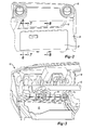
- FIG. 2 is a partial front view of an instrument panel including an open bin, glove box, IPR and a lower trim panel;
- FIG. 3 is a partial rear view of an instrument panel including a glove box, IPR and a lower trim panel;
- FIG. 4 is a partial front view of an instrument panel including an open bin, glove box, IPR and a lower trim panel;
- FIG. 5 is a partial rear view of an instrument panel including an open bin, decorative trim, glove box and a lower trim panel;
- FIG. 6 is a partial section view taken along the line A-A detailing the instrument panel, glove box, bracket, IPR and lower trim panel;
- FIG. 7 is a partial section view taken along the line B-B detailing the instrument panel, glove box, bracket, IPR and lower trim panel;
- FIG. 8 is a partial section view taken along the line C-C detailing the instrument panel, glove box, bracket, IPR and lower trim panel.
- the embodiments described herein generally relate to systems within a vehicle associated with the instrument panel for absorbing energy from a passenger coming into contact with the instrument panel in the event of a collision.
- the energy absorption systems generally include instrument panel reinforcements, trim panels, and instrument panels or instrument panel assemblies. Energy absorption systems and related components will be described in more detail herein.
- An energy absorption system 10 includes instrument panel reinforcement (IPR) 12 and at least one bracket 14 secured to the instrument panel reinforcement 12 .
- the energy absorbing system 10 also includes a one piece instrument panel 16 that has an open bin structure 18 formed thereon.
- An opening 20 is formed in the instrument panel 16 and receives a glove box structure 22 .
- a trim panel 24 is connected to the instrument panel 16 about the opening 20 and open bin structure 18 .
- the IPR 12 can extend from the passenger side of the vehicle to the driver side of the vehicle and can be formed of any metal, for example, steel.
- the IPR 12 can anchor a number of brackets 14 with two shown in the figures.
- the IPR may also anchor or connect to various components associated with the instrument panel assembly such as meters, gauges, audio and video accessories, HVAC accessories, airbags, and the like.
- the at least one bracket 14 may include a curved body 31 that absorbs energy through a controlled deformation.
- the body 31 may include a curve that extends downward to contact various structures as will be described in more detail below.
- the instrument panel 16 may be formed in one piece to reduce the complexity and weight of the component and to allow cost effective manufacture and a simplified installation.
- the instrument panel 16 includes at least one access window 26 formed therein allowing connection of components on a rear side of the instrument panel 16 .
- the open bin 18 shape may complicate the assembly of various components on a rear side of the instrument panel 16 .
- the access window 26 may be utilized to connected wire harnesses and modules 35 , as best shown in FIG. 4 .
- the instrument panel 16 may include a box structure 28 formed therein that is positioned adjacent the at least one access window 26 .
- the box structure 28 may receive an electronic control unit and provide a convenient attachment point not requiring a blind assembly.
- the instrument panel 16 may also include a decorative trim panel 30 disposed over the at least one access window 26 and the box structure 28 .
- the energy absorption system 10 may include multiple energy transfer paths that allow for the controlled dissipation of an impact force in the general direction as indicated by the direction arrow A.
- an impact force in the general direction as indicated by the direction arrow A.
- these forces are transferred and absorbed as will be discussed in more detail below.
- a first transfer and absorption path for the impact force includes the open bin structure 18 having a slot 36 formed therein receiving a fastener 38 connecting the open bin structure 18 to the bracket 14 .
- the impact force is applied to the glove box 22 at least a portion of the impact force is transferred through the open bin 18 and fastener 38 to the bracket 14 which provides a controlled absorption of the force.
- a second transfer and absorption path for the impact force includes the trim panel 24 having a slot 40 formed therein receiving a fastener 42 connecting the trim panel 24 to the instrument panel 16 .
- the impact force is applied to the glove box 22 at least a portion of the impact force is transferred through the trim panel 24 and fastener 42 to the instrument panel 16 .
- a third transfer and absorption path for the impact force includes the trim panel 24 having a slot 27 formed therein.
- the slot 27 receives a fastener 29 from the glove box 22 connecting the glove box 22 and trim panel 24 .
- the impact force is applied to the glove box 22 at least a portion of the impact force is transferred to the trim panel 24 .
- a fourth transfer and absorption path for the impact force includes the instrument panel 16 having at least one rib 46 formed thereon.
- the impact force is applied to the glove box 22 at least a portion of the impact force is transferred through the at least one instrument panel rib 46 to the bracket 14 .
- a fifth transfer and absorption path for the impact force includes the glove box 22 which travels along a path from an unengaged position to an engaged position.
- the glove box 22 contacts the trim panel 24 transferring at least a portion of the impact force to the trim panel 24 .
- the trim panel 24 includes a contact structure 48 that engages the at least one bracket 14 to absorb at least a portion of the impact force, when the glove box 22 is in the engaged position.
- a sixth transfer and absorption path for the impact force includes the trim panel 24 having at least one panel rib 44 formed thereon.
- the impact force is applied to the glove box 22 at least a portion of the impact force is transferred through the at least one trim panel rib 44 to the instrument panel 16 .
- the at least one bracket 14 may be located according to one or more lower leg intrusion points.
- the lower leg intrusion points may represent the path that the knees of a typical passenger may take during a collision. The knees may travel in an arcing-motion as the legs rotate about the ankle towards the instrument panel 16 .
- an energy absorbing bracket 14 can be securely attached to the IPR 12 at a first knee position, and a second energy absorbing bracket 14 can be securely attached to the IPR 12 at a second knee position.
- the energy absorption system 10 described above can be configured to dissipate a portion of the energy applied to the instrument panel 16 and glove box 22 upon the application of an impact force such as from the knees of a passenger resulting from a collision.
- the instrument panel 16 and glove box 22 is located in a position such that the trim panel 24 contact structure 48 is spaced at a distance d from the bracket 14 in an unengaged position.
- the glove box 22 moves in a direction corresponding to the arrow A such that the glove box 22 contacts the trim panel 24 and moves the trim panel 24 such that it traverses the distance d and is forced into an engagement position wherein it engages and contacts the bracket 14 .
- Such a traversal operates to absorb a portion of the impact energy or force and transfer the force to the brackets 14 .
- the impact force is also dissipated and absorbed by the additional travel and absorption paths as described above.
- the bracket 14 may deflect or deform such that a portion of the impact energy is absorbed in a controlled manner. Either by deflection or deformation, the impact force is transferred to the brackets 14 and IPR 12 .
Landscapes
- Engineering & Computer Science (AREA)
- Mechanical Engineering (AREA)
- Chemical & Material Sciences (AREA)
- Combustion & Propulsion (AREA)
- Transportation (AREA)
- Vehicle Step Arrangements And Article Storage (AREA)
- Instrument Panels (AREA)
Abstract
Description
Claims (17)
Priority Applications (1)
| Application Number | Priority Date | Filing Date | Title |
|---|---|---|---|
| US14/601,688 US9457755B2 (en) | 2015-01-09 | 2015-01-21 | One piece instrument panel with molded upper bin |
Applications Claiming Priority (2)
| Application Number | Priority Date | Filing Date | Title |
|---|---|---|---|
| US201562101529P | 2015-01-09 | 2015-01-09 | |
| US14/601,688 US9457755B2 (en) | 2015-01-09 | 2015-01-21 | One piece instrument panel with molded upper bin |
Publications (2)
| Publication Number | Publication Date |
|---|---|
| US20160200277A1 US20160200277A1 (en) | 2016-07-14 |
| US9457755B2 true US9457755B2 (en) | 2016-10-04 |
Family
ID=56366949
Family Applications (1)
| Application Number | Title | Priority Date | Filing Date |
|---|---|---|---|
| US14/601,688 Expired - Fee Related US9457755B2 (en) | 2015-01-09 | 2015-01-21 | One piece instrument panel with molded upper bin |
Country Status (1)
| Country | Link |
|---|---|
| US (1) | US9457755B2 (en) |
Cited By (3)
| Publication number | Priority date | Publication date | Assignee | Title |
|---|---|---|---|---|
| US20160129870A1 (en) * | 2014-11-06 | 2016-05-12 | Hyundai Motor Company | Knee bolster device for vehicle |
| USD841544S1 (en) * | 2016-11-11 | 2019-02-26 | Jaguar Land Rover Limited | Interior panel for a vehicle |
| US20220266921A1 (en) * | 2021-02-23 | 2022-08-25 | Ford Global Technologies, Llc | Vehicle instrument panel assembly |
Families Citing this family (1)
| Publication number | Priority date | Publication date | Assignee | Title |
|---|---|---|---|---|
| US10246912B2 (en) * | 2016-11-18 | 2019-04-02 | Ford Global Technologies Llc | Locator feature for automotive interior doors |
Citations (32)
| Publication number | Priority date | Publication date | Assignee | Title |
|---|---|---|---|---|
| US4709943A (en) * | 1985-07-17 | 1987-12-01 | Mazda Motor Corporation | Knee protector structure for vehicle |
| US5085465A (en) * | 1989-09-07 | 1992-02-04 | Mazda Motor Corporation | Air bag structure for an automotive vehicle |
| US5190314A (en) * | 1990-07-04 | 1993-03-02 | Mazda Motor Corporation | Glove box structure of vehicle |
| US5482319A (en) * | 1992-12-15 | 1996-01-09 | Mazda Motor Corporation | Passenger protection device for an automotive vehicle |
| US5639116A (en) * | 1994-04-28 | 1997-06-17 | Honda Giken Kogyo Kabushiki Kaisha | Instrument panel structure in vehicle |
| US5865468A (en) * | 1995-07-28 | 1999-02-02 | Daewoo Motor Co., Ltd. | Knee bolster of a vehicle |
| US6176544B1 (en) * | 1997-12-19 | 2001-01-23 | Alcoa Inc. | Instrument panel reinforcement structure including a novel driver side cross tube |
| US6213504B1 (en) * | 1997-12-25 | 2001-04-10 | Suzuki Motor Corporation | Automobile knee bolster structure |
| US6299208B1 (en) * | 1998-05-15 | 2001-10-09 | Fuji Jukogyo Kabushiki Kaisha | Occupant protection structure |
| US6550835B2 (en) * | 2001-05-23 | 2003-04-22 | Lear Corporation | Method and apparatus for supporting an electrical circuit board in a vehicle panel closure |
| US6869123B2 (en) | 2001-11-26 | 2005-03-22 | General Electric Company | Instrument panel thermoplastic energy absorbers |
| US6896308B2 (en) * | 2003-05-16 | 2005-05-24 | Nissan Motor Co., Ltd. | Vehicle storage box structure |
| US7040686B2 (en) * | 2002-06-28 | 2006-05-09 | Collins & Aikman Products Co. | Integrated center stack electronic module retention system |
| US7201434B1 (en) | 2005-11-04 | 2007-04-10 | Cadence Innovation Llc | Energy-absorbing bolster for an automotive instrument panel assembly |
| US7290788B2 (en) * | 2003-09-03 | 2007-11-06 | Visteon Global Technologies, Inc. | Airbag bracket |
| US7311328B2 (en) | 2003-09-05 | 2007-12-25 | Salflex Polymers Ltd. | Instrument panel subassembly including a glove box door |
| US7484792B2 (en) * | 2006-02-07 | 2009-02-03 | Toyota Motor Engineering & Manufacturing North America, Inc. | Glove box assembly exhibiting knee impact force transferring structure with respect to an associated vehicle dash/instrument panel and reinforcing bar |
| US7703829B2 (en) * | 2008-01-11 | 2010-04-27 | Toyota Motor Engineering & Manufacturing North America, Inc. | Instrument panel energy transferring system |
| US7731261B2 (en) * | 2002-12-10 | 2010-06-08 | Inteva Products Llc | Integrated structural member for a vehicle and method of making |
| US7735866B2 (en) * | 2007-11-27 | 2010-06-15 | Toyota Motor Engineering & Manufacturing North America, Inc. | Glove box energy absorbing structure |
| US7810837B2 (en) * | 2009-02-03 | 2010-10-12 | Gm Global Technology Operations, Inc. | Inflatable restraint system with deployment trajectory controller |
| US7810869B2 (en) | 2008-10-07 | 2010-10-12 | Honda Motor Co., Ltd. | Glove box knee bolster assembly for vehicle and method of manufacturing |
| US7874587B2 (en) * | 2006-02-07 | 2011-01-25 | Toyota Motor Engineering & Manufacturing North America, Inc. | Glove box assembly exhibiting knee impact force transferring structure with respect to an associated vehicle dash/instrument panel and reinforcing bar and including removable strengthening ribs for tuning of crash safety characteristics |
| US7946640B2 (en) * | 2005-12-15 | 2011-05-24 | Komatsu Ltd. | Instrument panel, module, and vehicle |
| US8251399B2 (en) * | 2009-11-24 | 2012-08-28 | Toyota Motor Engineering & Manufacturing North America, Inc. | Instrument panel energy absorption systems |
| US8262131B2 (en) | 2009-07-21 | 2012-09-11 | Ford Global Technologies, Llc | Automotive knee bolster system |
| US8308186B1 (en) * | 2011-08-29 | 2012-11-13 | Ford Global Technologies, Llc | Active bolster mounting system |
| US8403392B2 (en) * | 2009-07-21 | 2013-03-26 | Honda Motor Co., Ltd. | Glove box for vehicle |
| US8424207B2 (en) * | 2008-10-27 | 2013-04-23 | Honda Motor Co., Ltd. | Method of making a composite component and apparatus |
| US8434810B2 (en) * | 2009-11-06 | 2013-05-07 | Suzuki Motor Corporation | Surrounding structure of storage compartment of instrument panel |
| US8668238B2 (en) * | 2010-11-22 | 2014-03-11 | Honda Motor Co., Ltd. | Glove box structure for vehicle |
| US20140103685A1 (en) * | 2011-02-23 | 2014-04-17 | Ayyakannu Mani | Lightweight Cross-Car Beam and Method of Construction |
-
2015
- 2015-01-21 US US14/601,688 patent/US9457755B2/en not_active Expired - Fee Related
Patent Citations (32)
| Publication number | Priority date | Publication date | Assignee | Title |
|---|---|---|---|---|
| US4709943A (en) * | 1985-07-17 | 1987-12-01 | Mazda Motor Corporation | Knee protector structure for vehicle |
| US5085465A (en) * | 1989-09-07 | 1992-02-04 | Mazda Motor Corporation | Air bag structure for an automotive vehicle |
| US5190314A (en) * | 1990-07-04 | 1993-03-02 | Mazda Motor Corporation | Glove box structure of vehicle |
| US5482319A (en) * | 1992-12-15 | 1996-01-09 | Mazda Motor Corporation | Passenger protection device for an automotive vehicle |
| US5639116A (en) * | 1994-04-28 | 1997-06-17 | Honda Giken Kogyo Kabushiki Kaisha | Instrument panel structure in vehicle |
| US5865468A (en) * | 1995-07-28 | 1999-02-02 | Daewoo Motor Co., Ltd. | Knee bolster of a vehicle |
| US6176544B1 (en) * | 1997-12-19 | 2001-01-23 | Alcoa Inc. | Instrument panel reinforcement structure including a novel driver side cross tube |
| US6213504B1 (en) * | 1997-12-25 | 2001-04-10 | Suzuki Motor Corporation | Automobile knee bolster structure |
| US6299208B1 (en) * | 1998-05-15 | 2001-10-09 | Fuji Jukogyo Kabushiki Kaisha | Occupant protection structure |
| US6550835B2 (en) * | 2001-05-23 | 2003-04-22 | Lear Corporation | Method and apparatus for supporting an electrical circuit board in a vehicle panel closure |
| US6869123B2 (en) | 2001-11-26 | 2005-03-22 | General Electric Company | Instrument panel thermoplastic energy absorbers |
| US7040686B2 (en) * | 2002-06-28 | 2006-05-09 | Collins & Aikman Products Co. | Integrated center stack electronic module retention system |
| US7731261B2 (en) * | 2002-12-10 | 2010-06-08 | Inteva Products Llc | Integrated structural member for a vehicle and method of making |
| US6896308B2 (en) * | 2003-05-16 | 2005-05-24 | Nissan Motor Co., Ltd. | Vehicle storage box structure |
| US7290788B2 (en) * | 2003-09-03 | 2007-11-06 | Visteon Global Technologies, Inc. | Airbag bracket |
| US7311328B2 (en) | 2003-09-05 | 2007-12-25 | Salflex Polymers Ltd. | Instrument panel subassembly including a glove box door |
| US7201434B1 (en) | 2005-11-04 | 2007-04-10 | Cadence Innovation Llc | Energy-absorbing bolster for an automotive instrument panel assembly |
| US7946640B2 (en) * | 2005-12-15 | 2011-05-24 | Komatsu Ltd. | Instrument panel, module, and vehicle |
| US7484792B2 (en) * | 2006-02-07 | 2009-02-03 | Toyota Motor Engineering & Manufacturing North America, Inc. | Glove box assembly exhibiting knee impact force transferring structure with respect to an associated vehicle dash/instrument panel and reinforcing bar |
| US7874587B2 (en) * | 2006-02-07 | 2011-01-25 | Toyota Motor Engineering & Manufacturing North America, Inc. | Glove box assembly exhibiting knee impact force transferring structure with respect to an associated vehicle dash/instrument panel and reinforcing bar and including removable strengthening ribs for tuning of crash safety characteristics |
| US7735866B2 (en) * | 2007-11-27 | 2010-06-15 | Toyota Motor Engineering & Manufacturing North America, Inc. | Glove box energy absorbing structure |
| US7703829B2 (en) * | 2008-01-11 | 2010-04-27 | Toyota Motor Engineering & Manufacturing North America, Inc. | Instrument panel energy transferring system |
| US7810869B2 (en) | 2008-10-07 | 2010-10-12 | Honda Motor Co., Ltd. | Glove box knee bolster assembly for vehicle and method of manufacturing |
| US8424207B2 (en) * | 2008-10-27 | 2013-04-23 | Honda Motor Co., Ltd. | Method of making a composite component and apparatus |
| US7810837B2 (en) * | 2009-02-03 | 2010-10-12 | Gm Global Technology Operations, Inc. | Inflatable restraint system with deployment trajectory controller |
| US8262131B2 (en) | 2009-07-21 | 2012-09-11 | Ford Global Technologies, Llc | Automotive knee bolster system |
| US8403392B2 (en) * | 2009-07-21 | 2013-03-26 | Honda Motor Co., Ltd. | Glove box for vehicle |
| US8434810B2 (en) * | 2009-11-06 | 2013-05-07 | Suzuki Motor Corporation | Surrounding structure of storage compartment of instrument panel |
| US8251399B2 (en) * | 2009-11-24 | 2012-08-28 | Toyota Motor Engineering & Manufacturing North America, Inc. | Instrument panel energy absorption systems |
| US8668238B2 (en) * | 2010-11-22 | 2014-03-11 | Honda Motor Co., Ltd. | Glove box structure for vehicle |
| US20140103685A1 (en) * | 2011-02-23 | 2014-04-17 | Ayyakannu Mani | Lightweight Cross-Car Beam and Method of Construction |
| US8308186B1 (en) * | 2011-08-29 | 2012-11-13 | Ford Global Technologies, Llc | Active bolster mounting system |
Cited By (6)
| Publication number | Priority date | Publication date | Assignee | Title |
|---|---|---|---|---|
| US20160129870A1 (en) * | 2014-11-06 | 2016-05-12 | Hyundai Motor Company | Knee bolster device for vehicle |
| US9751485B2 (en) * | 2014-11-06 | 2017-09-05 | Hyundai Motor Company | Knee bolster device for vehicle |
| USD841544S1 (en) * | 2016-11-11 | 2019-02-26 | Jaguar Land Rover Limited | Interior panel for a vehicle |
| USD874371S1 (en) * | 2016-11-11 | 2020-02-04 | Jaguar Land Rover Limited | Instrument panel for a vehicle |
| US20220266921A1 (en) * | 2021-02-23 | 2022-08-25 | Ford Global Technologies, Llc | Vehicle instrument panel assembly |
| US11603140B2 (en) * | 2021-02-23 | 2023-03-14 | Ford Global Technologies, Llc | Vehicle instrument panel assembly |
Also Published As
| Publication number | Publication date |
|---|---|
| US20160200277A1 (en) | 2016-07-14 |
Similar Documents
| Publication | Publication Date | Title |
|---|---|---|
| US5749600A (en) | Door trim energy absorbing structure | |
| US8333407B2 (en) | Knee bolster for vehicles | |
| US8167360B2 (en) | Vehicle cross member assembly with tunnel bracket | |
| US8251399B2 (en) | Instrument panel energy absorption systems | |
| CN104364142B (en) | The center pillar dividing plate weakened in Y-axis and strengthen on Z axis | |
| US9446795B2 (en) | Structure for reinforcing front vehicle body | |
| US9457755B2 (en) | One piece instrument panel with molded upper bin | |
| EP3196104B1 (en) | Cowl cross member for vehicle | |
| US9919747B2 (en) | Vehicle side impact sensing assembly | |
| KR100412906B1 (en) | front pillar panel assembly structure of vehicle | |
| US8491037B2 (en) | Extend and breakaway bracket for glove box | |
| CN106364318B (en) | Motor vehicle with dashboard | |
| US7344158B2 (en) | Mounting structure of steering column for vehicles | |
| JP5008458B2 (en) | Car body side structure | |
| US20160129870A1 (en) | Knee bolster device for vehicle | |
| JP6895236B2 (en) | Vehicle interior structure | |
| US9598110B2 (en) | Vehicle storage compartment assembly | |
| US6962380B2 (en) | Rear bumper assembly structure for vehicle | |
| KR20190040745A (en) | Side Reinforcing Vehicle Body Structure | |
| CN101190676A (en) | Dashboard support structure | |
| CA2449904A1 (en) | Rail vehicle, in particular lightweight motor car | |
| CN108001544B (en) | Instrument panel and front cowl attachment | |
| JPH0948292A (en) | Mounting structure for in-vehicle equipment | |
| KR101601326B1 (en) | Mounting structure of assist handle | |
| JP2017109703A (en) | Vehicle indoor structure |
Legal Events
| Date | Code | Title | Description |
|---|---|---|---|
| AS | Assignment |
Owner name: TOYOTA MOTOR ENGINEERING & MANUFACTURING NORTH AME Free format text: ASSIGNMENT OF ASSIGNORS INTEREST;ASSIGNOR:MERKEL, NICHOLAS EARL;REEL/FRAME:034897/0359 Effective date: 20150120 |
|
| STCF | Information on status: patent grant |
Free format text: PATENTED CASE |
|
| AS | Assignment |
Owner name: TOYOTA JIDOSHA KABUSHIKI KAISHA, JAPAN Free format text: ASSIGNMENT OF ASSIGNORS INTEREST;ASSIGNOR:TOYOTA MOTOR ENGINEERING & MANUFACTURING NORTH AMERICA, INC.;REEL/FRAME:040043/0818 Effective date: 20161007 |
|
| MAFP | Maintenance fee payment |
Free format text: PAYMENT OF MAINTENANCE FEE, 4TH YEAR, LARGE ENTITY (ORIGINAL EVENT CODE: M1551); ENTITY STATUS OF PATENT OWNER: LARGE ENTITY Year of fee payment: 4 |
|
| FEPP | Fee payment procedure |
Free format text: MAINTENANCE FEE REMINDER MAILED (ORIGINAL EVENT CODE: REM.); ENTITY STATUS OF PATENT OWNER: LARGE ENTITY |
|
| LAPS | Lapse for failure to pay maintenance fees |
Free format text: PATENT EXPIRED FOR FAILURE TO PAY MAINTENANCE FEES (ORIGINAL EVENT CODE: EXP.); ENTITY STATUS OF PATENT OWNER: LARGE ENTITY |
|
| STCH | Information on status: patent discontinuation |
Free format text: PATENT EXPIRED DUE TO NONPAYMENT OF MAINTENANCE FEES UNDER 37 CFR 1.362 |
|
| FP | Lapsed due to failure to pay maintenance fee |
Effective date: 20241004 |