US945460A - Agricultural implement. - Google Patents
Agricultural implement. Download PDFInfo
- Publication number
- US945460A US945460A US45684508A US1908456845A US945460A US 945460 A US945460 A US 945460A US 45684508 A US45684508 A US 45684508A US 1908456845 A US1908456845 A US 1908456845A US 945460 A US945460 A US 945460A
- Authority
- US
- United States
- Prior art keywords
- frame
- plow
- agricultural implement
- plows
- beams
- Prior art date
- Legal status (The legal status is an assumption and is not a legal conclusion. Google has not performed a legal analysis and makes no representation as to the accuracy of the status listed.)
- Expired - Lifetime
Links
- 229910000746 Structural steel Inorganic materials 0.000 description 2
- 238000010276 construction Methods 0.000 description 2
- 230000000994 depressogenic effect Effects 0.000 description 2
- 241001080526 Vertica Species 0.000 description 1
- 230000005540 biological transmission Effects 0.000 description 1
- 238000002485 combustion reaction Methods 0.000 description 1
- 230000003028 elevating effect Effects 0.000 description 1
- 239000002360 explosive Substances 0.000 description 1
- 239000002689 soil Substances 0.000 description 1
Images
Classifications
-
- A—HUMAN NECESSITIES
- A01—AGRICULTURE; FORESTRY; ANIMAL HUSBANDRY; HUNTING; TRAPPING; FISHING
- A01C—PLANTING; SOWING; FERTILISING
- A01C5/00—Making or covering furrows or holes for sowing, planting or manuring
- A01C5/06—Machines for making or covering drills or furrows for sowing or planting
Definitions
- This invention comprises the construction of an agricultural implement provided with improved driving means and with a double set oflows arranged to be vertically adjusted rom the rear of the machine.
- One of the objects of the invention is the provision of an agricultural implement havin a forward and a rear set of plows with 'in ependent adjustment means arranged to i be operated from the rear of the machine.
- Another object of .the invention is the proiduction of "an agricultural implement with a frame of angle iron and motive power means arranged on the frame and connected with the traction wheels.
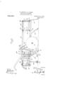
- Fi ure 1 is a central longitudinal sectiona view
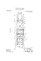
- Fi 2 is a top plan View
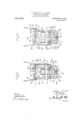
- Fig. 3 is a front en view
- Fig. 4 is a rear end view.
- Numeral 1 designates the frame, which is preferably formed of angle iron, and comprises a base portion, 2, which is rectangular in form, a plurality of vertical bars, 3, and a top portion, 4, which is also rectangular in form.
- the base portion, 2, of the frame, 1, is provided with centrally disposed bearing blocks, 5, and an axle which carries a traction wheel, 7, and a sprocket wheel, 8.
- the forward end of the frame, 1, is provided with vertically arranged guideways, 9, which are ada ted to receive the opposite ends of a mova le cross bar, 10, which is provided with adjustable plow b eam supports, 11, said supports be ng formed with transverse openings, 12.
- a second cross bar, 13, is rigidly secured, on the frame, 1, and rearwarc ly of the cross bar, 10, and carries a plurality of inverted U-shaped plow beam supports, 14, havin openings, 15, formed therein.
- a plura ity of angular plow beams or standards, l6, having their upper ends disposed in a horizontal plane are pivotally secured to the supports 11 and 14, which are spaced apart.
- One end of each port, 14, and the middle portion of said earn is secured in the forward support.
- the lower ends of the plow beams, 16, are formed with openings. 17, for accommodat ing plow fastening bolts.
- the rear end of the frame, 1, is provided with vertical guideways, 18, which are mounted on said frame, and said guideways are adapted to accommodate opposite ends of a slidable cross bar, 19, which is provided with adjustable plow beam supports, 20,- formed with openings, 21.
- the rear cross bar, 22, of the frame. 1, is provided with two inverted U-shaped adjustable plow beam supports, 23, which are formed with openings, 24.
- the rear supports pivotally sustain plow beams or standards, 26, which have their up or ends disposed in a horizonl tal plane, and are adapted to carry on their of the plow beams, 16, is secured in the sup- Y-shaped operating has connected nects by means wheel shaft 6.
- the forward slidable cross bar, 10, is engaged on opposite sides by chains, 27 and 28, which engage pulleys, 29, and pass through guides, 30, arranged on the frame, 1, and said chains are connected at 31, to a rearwardly extending chain, 32.
- the chain, 32 passes through a guide, 83, and connects with a lever, 3st, which is pivotally supported on the frame, I, and is adapted to engage with a rack or lock, When the rear end of the lever 3d, is depressed the chains, 27 and :28, will elevate the slidable cross bar, 10, and the plows carried. thereon.
- the rear slidable cross bar, 19, is connected to upwardly extending chains, 36 and 37, and a lever, 38, is connected to these chains, and is pivotally supported on the frame, 1. llhendepressed the lever, 38, will elevate the rear plow beams, 25, and is held in its depressed position by a rack or latch, 39, which is pivoted to the base portion, 2. v I
- a clearer is preferably carried by a standard, 43, forwardly of the tractionwheel, 7, and a sod crusher, i4, is preferably carried by a standard, le, rearwardly of the rear plows.
- a hopper, 45 is supported on the frame, 1, rearwardly of the traction wheel, 7, and,
- a drill feeding chute 46.
- Communication between the chute, '16, and the hopper, 45, is controlled by a seed shut-off or slide, 47, which is carried by a lever, 48,pivotally supported on the hopper, 45, and arranged toengage a segment, 49, which is secured to the upper part ofthe hopper.
- a shaft, '50 extends across the hopper, 45, and carries a shaker or agitator, 51, and said shaft.
- axle or traction be ofany approved type such as an internal combustion engine, comprising an explosive chamber, a fireplug,'a pistonand a fly wheel, is-mounted on the topportion of frame, 4, and conof a chain-and sprocket, 54;,
- a motor which may 1 i f arranged on its crank shaft, 55, with a larger sprocket wheel, 56,";C ttll'led by a shaft, 57,
- the motor is pro vided with the usual accessories and isadapted .to propel the machine over the ground in such a manner that the operator will have nothing to do but to steer the machine and operate the motor. may be provided withany number of wheels, which may be connected with the driving motor.
- the forward plows are adapted to prepare the ground for thereception of seeds from the hopper, which are deposited with the assistance of a suitable drill, and the clearer is adapted to remove obstructions from the path of the traction wheel.
- the rear lows are arranged to finishthe work of en tivation, which is assisted by the seed coverin plows, and the sod crusher roller is adapte The frame to smooth out any roughness in the ground. What we claim and desire to secure by Letters Patent is: p v
- a frame comprising an angular bottom portion and w an angular top portion, angular vertical members connected to the bottom and to portions, guideways formed on the vertica members, supports having spaced apertures therein, slidable on the guideways, angular plow beams adapted to be pivoted in either of the apertures of thesupports, a chain .connected with the forward support, extending rearwardly thereof, a clearer projecting forwardly the rear of the frame, supports having spaced'apertures movable on the guideways, an angular plow beam adapted to be pivoted in either of the apertures of said supports, seed-feeding mechanism positioned above the last plow having a plow at its lower end extending rearwardly of the lower. plow beam.
- said vertical projections two subscribing witnesses. being pivotally connected with said beams yVILLIAM HOOVER intermediate their ends, means for raising EDWARD (1 GATES 5 and lowering i momble cross b Said witnesseses as to the signature of William plow beams having plows on their lower ends adapted to prepare the soil for the ref R ception of seed, seed feeding'mechanism arranged in the rear of said plows and a sec- ODGES' 10, 0nd set of plows arranged in the rear of said l/Vltnesses as t slgnature of Edward seed feedi g mechanism for covering the Gates? seed. J. PEAcooK,
Landscapes
- Life Sciences & Earth Sciences (AREA)
- Soil Sciences (AREA)
- Environmental Sciences (AREA)
- Soil Working Implements (AREA)
Description
' 19M eons W, HOOVER & E. 0. GATES.
AGRICULTURAL IMPLEMENT. 7 APPLICATION FILED OUT. 8, 1908. v 9%5,%6G, Eateaizai 3 191% 3 B EEET 1.
enwe Conw- W. HCQVER & E. 0. GATES. AGRICULTURAL IMPLEMENT. 7 APPLICATION 111L111) OCT. 8, 190 8. 945,466, Patented 52111.4,1910.
3 sHEETssHr;BT 2.
W. HOOVER 8; E. G. GATES.
AGRICULTURAL IMPLEMENT.
APPLICATION FILED OUT. 8, 190B.
Patented Jan. 4-, 1910.
avwentozm wihwaoao awczmu o UNITED sra'ras WILLIAM HOOVER AND EDWARD C. GATES, OF MACCLENNY, FLORIDA.
AGRICULTURAL IMPLEMENT,
Specification of Letters ratent.
Patented Jan. 4., 1910.
Application filed October 8, 1998. Serial No. 456,845.
-Others skilled in the art to which it appertains to make and use the same.
This invention comprises the construction of an agricultural implement provided with improved driving means and with a double set oflows arranged to be vertically adjusted rom the rear of the machine.
*One of the objects of the invention is the provision of an agricultural implement havin a forward and a rear set of plows with 'in ependent adjustment means arranged to i be operated from the rear of the machine.
7 Another object of the invention is the pro vision of an agricultural implement having a forward and a rear set of plows or culti= vat'ing tools, with chain means operative fromthe rear of the machine for independently and vertically adjusting each set of plows or cultivatingtools.
Another object of .the invention is the proiduction of "an agricultural implement with a frame of angle iron and motive power means arranged on the frame and connected with the traction wheels.
With the above and other objects in view this invention comprises certain constructions, combinations, and arrangements of parts described in the specification and illustrated in the accompanying drawings, in which,
Fi ure 1 is a central longitudinal sectiona view, Fi 2 is a top plan View, Fig. 3 is a front en view, Fig. 4 is a rear end view.
Corresponding and similar-parts are referred to'in the following specification and in all the views of the drawings by similar reference characters.
In the accompanying drawings we have illustrated-the preferred embodiment of our invention, and it is understood that the drawings are repared for illustrative purposles only, and are therefore not prepared to sea e.
Numeral 1, designates the frame, which is preferably formed of angle iron, and comprises a base portion, 2, which is rectangular in form, a plurality of vertical bars, 3, and a top portion, 4, which is also rectangular in form. The base portion, 2, of the frame, 1, .is provided with centrally disposed bearing blocks, 5, and an axle which carries a traction wheel, 7, and a sprocket wheel, 8.
The forward end of the frame, 1, is provided with vertically arranged guideways, 9, which are ada ted to receive the opposite ends of a mova le cross bar, 10, which is provided with adjustable plow b eam supports, 11, said supports be ng formed with transverse openings, 12. A second cross bar, 13, is rigidly secured, on the frame, 1, and rearwarc ly of the cross bar, 10, and carries a plurality of inverted U-shaped plow beam supports, 14, havin openings, 15, formed therein. A plura ity of angular plow beams or standards, l6, having their upper ends disposed in a horizontal plane are pivotally secured to the supports 11 and 14, which are spaced apart. One end of each port, 14, and the middle portion of said earn is secured in the forward support. The lower ends of the plow beams, 16, are formed with openings. 17, for accommodat ing plow fastening bolts.
The rear end of the frame, 1, is provided with vertical guideways, 18, which are mounted on said frame, and said guideways are adapted to accommodate opposite ends of a slidable cross bar, 19, which is provided with adjustable plow beam supports, 20,- formed with openings, 21. The rear cross bar, 22, of the frame. 1, is provided with two inverted U-shaped adjustable plow beam supports, 23, which are formed with openings, 24. The rear supports pivotally sustain plow beams or standards, 26, which have their up or ends disposed in a horizonl tal plane, and are adapted to carry on their of the plow beams, 16, is secured in the sup- Y-shaped operating has connected nects by means wheel shaft 6.
lower ends, which are formed with suitable bolt openings, 26, a set of plows.
The forward slidable cross bar, 10, is engaged on opposite sides by chains, 27 and 28, which engage pulleys, 29, and pass through guides, 30, arranged on the frame, 1, and said chains are connected at 31, to a rearwardly extending chain, 32. The chain, 32, passes through a guide, 83, and connects with a lever, 3st, which is pivotally supported on the frame, I, and is adapted to engage with a rack or lock, When the rear end of the lever 3d, is depressed the chains, 27 and :28, will elevate the slidable cross bar, 10, and the plows carried. thereon. The rear slidable cross bar, 19, is connected to upwardly extending chains, 36 and 37, and a lever, 38, is connected to these chains, and is pivotally supported on the frame, 1. llhendepressed the lever, 38, will elevate the rear plow beams, 25, and is held in its depressed position by a rack or latch, 39, which is pivoted to the base portion, 2. v I
A. pair of detachably secured plow beams or standards, 40, which are adapted to carry seed covering plows, are arranged on op posite sides of the base portion, 2, and project rearwardly. A drill or furrow opening wedge-disk, ll, is rotatably supported on a standard, 42, nearwardly of the traction wheel, T. A clearer is preferably carried by a standard, 43, forwardly of the tractionwheel, 7, and a sod crusher, i4, is preferably carried by a standard, le, rearwardly of the rear plows.
A hopper, 45, is supported on the frame, 1, rearwardly of the traction wheel, 7, and,
thereto a drill feeding chute, 46. Communication between the chute, '16, and the hopper, 45, is controlled by a seed shut-off or slide, 47, which is carried by a lever, 48,pivotally supported on the hopper, 45, and arranged toengage a segment, 49, which is secured to the upper part ofthe hopper. A shaft, '50, extends across the hopper, 45, and carries a shaker or agitator, 51, and said shaft. is connected to a rocking link, 52, by means of a crank arm, 53, formed thereon, with the axle or traction be ofany approved type such as an internal combustion engine, comprising an explosive chamber, a fireplug,'a pistonand a fly wheel, is-mounted on the topportion of frame, 4, and conof a chain-and sprocket, 54;,
A motor, which may 1 i f arranged on its crank shaft, 55, with a larger sprocket wheel, 56,";C ttll'led by a shaft, 57,
journaled on the top portion of frame, 4,. which shaft is provided with a transmission gear, 58, and an intermediate sprocket, 59,
which sprocket connects by a chain, 60, the
traction wheel shaft,6. The motor is pro vided with the usual accessories and isadapted .to propel the machine over the ground in such a manner that the operator will have nothing to do but to steer the machine and operate the motor. may be provided withany number of wheels, which may be connected with the driving motor. I
The forward plows are adapted to prepare the ground for thereception of seeds from the hopper, which are deposited with the assistance of a suitable drill, and the clearer is adapted to remove obstructions from the path of the traction wheel. The rear lows are arranged to finishthe work of en tivation, which is assisted by the seed coverin plows, and the sod crusher roller is adapte The frame to smooth out any roughness in the ground. What we claim and desire to secure by Letters Patent is: p v
1. In an agricultural implement, a frame comprising an angular bottom portion and w an angular top portion, angular vertical members connected to the bottom and to portions, guideways formed on the vertica members, supports having spaced apertures therein, slidable on the guideways, angular plow beams adapted to be pivoted in either of the apertures of thesupports, a chain .connected with the forward support, extending rearwardly thereof, a clearer projecting forwardly the rear of the frame, supports having spaced'apertures movable on the guideways, an angular plow beam adapted to be pivoted in either of the apertures of said supports, seed-feeding mechanism positioned above the last plow having a plow at its lower end extending rearwardly of the lower. plow beam.
2. In an agricultural implement, a frame; 1
a traction wheel journaled to the frame, for-; ward plow beams carried by the frame, means for adjusting the plowv beams, means extending rearwardly for elevating the plow beams, seed feeding means arranged on the frame, a clearer supported on the frame extending forwardly of the traction wheel, seed covering plows arranged rearwardly of the seed feeding mechanism, rear plow beams, means for adjustably su porting'the rear-plow beams, chains for e evating the rear plow beams, on the frame.
3. "In an agricultural implement, a frame, angularly disposed plow beams extending forwardly of said frame, guideposts'mounted on each side of the front endof said frame, a. movable cross bar carried by said .frame, andeach end thereof bieing' guided by said guideposts, vertic a l proy'ections rigidly connected with said movafo e cross bar, stationary beam supports connected with the secured to the frame, guidewayson beam and a plow beam,
and a sod roller supported end' of the angular inner ends of said beamsand capable ofadnames to thisspecification in the presence of justing said beams, said vertical projections two subscribing witnesses. being pivotally connected with said beams yVILLIAM HOOVER intermediate their ends, means for raising EDWARD (1 GATES 5 and lowering i momble cross b Said Witnesses as to the signature of William plow beams having plows on their lower ends adapted to prepare the soil for the ref R ception of seed, seed feeding'mechanism arranged in the rear of said plows and a sec- ODGES' 10, 0nd set of plows arranged in the rear of said l/Vltnesses as t slgnature of Edward seed feedi g mechanism for covering the Gates? seed. J. PEAcooK,
In testimony whereof we have signed our R. J. CAVENS.
Priority Applications (1)
| Application Number | Priority Date | Filing Date | Title |
|---|---|---|---|
| US45684508A US945460A (en) | 1908-10-08 | 1908-10-08 | Agricultural implement. |
Applications Claiming Priority (1)
| Application Number | Priority Date | Filing Date | Title |
|---|---|---|---|
| US45684508A US945460A (en) | 1908-10-08 | 1908-10-08 | Agricultural implement. |
Publications (1)
| Publication Number | Publication Date |
|---|---|
| US945460A true US945460A (en) | 1910-01-04 |
Family
ID=3013882
Family Applications (1)
| Application Number | Title | Priority Date | Filing Date |
|---|---|---|---|
| US45684508A Expired - Lifetime US945460A (en) | 1908-10-08 | 1908-10-08 | Agricultural implement. |
Country Status (1)
| Country | Link |
|---|---|
| US (1) | US945460A (en) |
-
1908
- 1908-10-08 US US45684508A patent/US945460A/en not_active Expired - Lifetime
Similar Documents
| Publication | Publication Date | Title |
|---|---|---|
| US3128833A (en) | Planting and cultivating device | |
| US1497695A (en) | Tractor | |
| US640514A (en) | Harrow and clod-crusher. | |
| US1211241A (en) | Agricultural implement. | |
| US1158680A (en) | Tractor for plows and cultivators. | |
| US1782560A (en) | Tractor stalk chopper | |
| US1342815A (en) | Tractor rotary plow | |
| US1094277A (en) | Motor plow and planter. | |
| US1167429A (en) | Motor plow and cultivator. | |
| US1316359A (en) | Motor-driven agricultural tool | |
| US1231352A (en) | Power-driven cultivator. | |
| US1175003A (en) | Combined weeder and cultivator. | |
| US3680640A (en) | Garden tractor | |
| US464561A (en) | Cultivator | |
| US1054609A (en) | Cultivator. | |
| US1273496A (en) | Agricultural implement. | |
| US1232420A (en) | Agricultural vehicle. | |
| US664686A (en) | Cultivator and harrow. | |
| US740633A (en) | Agricultural implement. | |
| US1040990A (en) | Cultivator. | |
| US1302295A (en) | Agricultural tractor. | |
| US1179532A (en) | Combined harrow and seeding-machine. | |
| US1886691A (en) | Cultivator | |
| US988315A (en) | Implement for plowing and otherwise cultivating land. | |
| US1198698A (en) | Tractor. |