US9446740B2 - Windshield wiper assembly - Google Patents
Windshield wiper assembly Download PDFInfo
- Publication number
- US9446740B2 US9446740B2 US14/027,554 US201314027554A US9446740B2 US 9446740 B2 US9446740 B2 US 9446740B2 US 201314027554 A US201314027554 A US 201314027554A US 9446740 B2 US9446740 B2 US 9446740B2
- Authority
- US
- United States
- Prior art keywords
- rib
- mounting bracket
- windshield wiper
- wiper assembly
- projection
- Prior art date
- Legal status (The legal status is an assumption and is not a legal conclusion. Google has not performed a legal analysis and makes no representation as to the accuracy of the status listed.)
- Expired - Fee Related, expires
Links
Images


Classifications
-
- B—PERFORMING OPERATIONS; TRANSPORTING
- B60—VEHICLES IN GENERAL
- B60S—SERVICING, CLEANING, REPAIRING, SUPPORTING, LIFTING, OR MANOEUVRING OF VEHICLES, NOT OTHERWISE PROVIDED FOR
- B60S1/00—Cleaning of vehicles
- B60S1/02—Cleaning windscreens, windows or optical devices
- B60S1/04—Wipers or the like, e.g. scrapers
- B60S1/06—Wipers or the like, e.g. scrapers characterised by the drive
- B60S1/16—Means for transmitting drive
- B60S1/166—Means for transmitting drive characterised by the combination of a motor-reduction unit and a mechanism for converting rotary into oscillatory movement
-
- B—PERFORMING OPERATIONS; TRANSPORTING
- B60—VEHICLES IN GENERAL
- B60S—SERVICING, CLEANING, REPAIRING, SUPPORTING, LIFTING, OR MANOEUVRING OF VEHICLES, NOT OTHERWISE PROVIDED FOR
- B60S1/00—Cleaning of vehicles
- B60S1/02—Cleaning windscreens, windows or optical devices
- B60S1/04—Wipers or the like, e.g. scrapers
- B60S1/0413—Modular wiper assembly
- B60S1/0422—Modular wiper assembly having a separate transverse element
- B60S1/0427—Modular wiper assembly having a separate transverse element characterised by the attachment of the wiper motor holder to the transverse element
-
- H—ELECTRICITY
- H02—GENERATION; CONVERSION OR DISTRIBUTION OF ELECTRIC POWER
- H02K—DYNAMO-ELECTRIC MACHINES
- H02K5/00—Casings; Enclosures; Supports
- H02K5/04—Casings or enclosures characterised by the shape, form or construction thereof
- H02K5/22—Auxiliary parts of casings not covered by groups H02K5/06-H02K5/20, e.g. shaped to form connection boxes or terminal boxes
-
- B—PERFORMING OPERATIONS; TRANSPORTING
- B60—VEHICLES IN GENERAL
- B60S—SERVICING, CLEANING, REPAIRING, SUPPORTING, LIFTING, OR MANOEUVRING OF VEHICLES, NOT OTHERWISE PROVIDED FOR
- B60S1/00—Cleaning of vehicles
- B60S1/02—Cleaning windscreens, windows or optical devices
- B60S1/04—Wipers or the like, e.g. scrapers
- B60S1/043—Attachment of the wiper assembly to the vehicle
- B60S1/0433—Attachement of a wiper modular assembly to the vehicle
Definitions
- the present invention relates to a vehicle windshield wiper assembly.
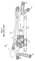
- a conventional windshield wiper assembly 200 typically includes a wiper motor 210 , one or more wiper blades secured to wiper arms, and a pivotable linkage mechanism therebetween.
- the wiper motor 210 has a housing 211 and a motor 220 which is connected to the housing 211 .
- the housing 211 has a top surface 212 and a side surface 213 .
- a projection 214 extends from the top surface 212 .
- the projection 214 pivotally supports an output shaft 230 of the wiper motor 210 . When the wiper motor 210 is driven, the output shaft 230 rotates in a predetermined direction r 1 .
- the wiper motor 210 has a mounting bracket 215 integrally formed with the side surface 213 .
- the mounting bracket 215 is attached to a bar when mounted within a vehicle.
- the wiper assembly 200 is mounted to the vehicle at mounting parts 250 .
- a link mechanism 260 which is attached to the output shaft 230 moves back and forth in predetermined ranges r 2 , r 3 and r 4 due to rotation of the wiper motor 210 . As a result, the wiper arms reciprocate along a windshield.
- this windshield wiper assembly includes a wiper motor including a housing having a top surface and a side surface, a projection projecting from the top surface, a mounting bracket integrally extending from the side surface, and a rib integrally extending from the top surface and from the projection to a longitudinal end of the mounting bracket.
- a wiper motor including a housing having a top surface and a side surface, a projection projecting from the top surface, a mounting bracket integrally extending from the side surface, and a rib integrally extending from the top surface and from the projection to a longitudinal end of the mounting bracket.
- FIG. 1 is a perspective view of a cut away cowl cover plate which shows a windshield wiper assembly in the mounted state according to an embodiment of the present invention.
- FIG. 2 is a front view of a wiper windshield assembly according to an embodiment of the present invention.
- FIG. 3 is a perspective view of a wiper motor of the present invention.
- FIG. 4 is a perspective view of a gear housing of the wiper motor to the present invention.
- FIG. 5A is a side view of the gear housing as seen from the direction of an arrow 5 A in FIG. 4 .
- FIG. 5B is a sectional view of the gear housing taken along line 5 B- 5 B in FIG. 4 .
- FIG. 6 is a front view of a windshield wiper assembly according to the related art.
- FIG. 7 is a perspective view of a wiper motor according to the related art.
- a vehicle 10 includes a windshield 11 and a body panel 12 .
- the body panel 12 includes a cowl box 13 and a cowl cover plate 14 which covers the cowl box 13 .
- a windshield wiper assembly 100 is mounted within the cowl box 13 .
- the wiper assembly 100 includes a first pivot assembly 110 , which includes a first pivot shaft 111 , a first pivot lever 112 , a first shaft supporting portion 113 , a first pivot cap 114 , a first bar coupling portion 115 , and first body mounting parts 116 , 116 .
- the wiper assembly 100 includes a second pivot assembly 120 , which includes a second pivot shaft 121 , a second pivot lever 122 , a second shaft supporting portion 123 , a second pivot cap 124 , a second bar coupling portion 125 , and second body mounting parts 126 , 126 . Further, the wiper assembly 100 includes a bar 130 and a link mechanism 140 .
- the first and second pivot shafts 111 and 121 are preferably formed of metal, and have an elongated cylindrical shape.
- the first and second pivot levers 112 and 122 are preferably formed of metal, and have a rectangular and thin plate shape.
- a first end of the first pivot shaft 111 is coupled to a first end of the first pivot lever 112 .
- a first end of the second pivot shaft 121 is coupled to a first end of the second pivot lever 122 .
- the first and second shaft supporting portions 113 and 123 are preferably formed of metal or plastic, and have a cylindrical bore shape.
- the first pivot shaft 111 is inserted into the first shaft supporting portion 113 so that the first pivot shaft 111 is pivotally supported by the first shaft supporting portion 113 .
- the second pivot shaft 121 is also inserted into the second shaft supporting portion 123 so that the second pivot shaft 121 is pivotally supported by the second shaft supporting portion 123 .
- the first pivot cap 114 is attached to the first pivot shaft 111 or the first shaft supporting portion 113 so that grease is encased by the first pivot cap 114 .
- the second pivot cap 124 is attached to the second pivot shaft 121 or the second shaft supporting portion 123 so that grease is encased by the second pivot cap 124 .
- the first and second bar coupling portions 115 and 125 are preferably formed of metal or plastic, and are integrally formed with the first and second shaft supporting portions 113 and 123 so that they project outwardly from the sides of the first and second shaft supporting portions 113 and 123 .
- the first and second bar coupling portions 115 and 125 are generally an elongated cylinder, for example, 23 mm in diameter, with a circular cross-section, and are coupled to both ends of the bar 130 by any suitable method of mounting such as press-fitting, swaging, or via threaded fasteners.
- the first and second body mounting parts 116 and 126 are preferably formed of metal or plastic, and are integrally formed with the first and second shaft supporting portions 113 and 123 .
- the first and second body mounting parts 116 and 126 are mounted on the cowl box 13 by, for example, bolts. As such, the first and second bar coupling portions 115 and 125 are maintained stationary relative to the cowl box 13 while the first and second pivot levers 112 and 122 are pivotable about the first and second pivot shafts 111 and 121 .
- the bar 130 is preferably formed of metal, and is generally an elongated straight cylinder, for example, 25 mm in diameter, with a circular cross-section that is cut to a predetermined length, for example, 300 mm.
- the first bar coupling portion 115 is coupled to a first end 130 a of the bar 130 by, for example, press-fitting or swaging.
- the second bar coupling portion 125 is coupled to a second end 130 b of the bar 130 by, for example, press-fitting or swaging.
- first and second bar coupling portions 115 and 125 may be inserted within both ends to enhance the interconnection therebetween.
- the link mechanism 140 includes first and second link rods 141 and 142 .
- the first and second link rods 141 and 142 are preferably formed of metal although other materials may substitute therefor.
- the link mechanism 140 is pivotally connected to the first and second pivot levers 112 and 122 .
- the second end 112 b of the first pivot lever 112 is pivotally connected to a first end 141 a of the first link rod 141 .
- the second end 122 b of the second pivot lever 122 is pivotally connected to a second end 141 b of the first link rod 141 .
- the second end 122 b of the second pivot lever 122 is pivotally connected to a first end 142 a of the second link rod 142 .
- the wiper motor 150 includes a motor 151 , and a housing 152 which is coupled to the motor 151 .
- the wiper motor 150 is directly mounted on one side of the bar 130 , and between the first and second bar coupling portions 115 and 125 by, for example, bolts and nuts.
- the wiper motor 150 rotates in the predetermined range R 1
- the first and second levers 112 and 122 move in predetermined ranges R 2 , R 3 and R 4 .
- the first and second link rods 141 and 142 move back and forth with the first and second levers 112 and 122 .
- the housing 152 is preferably formed of metal or plastic, and is integrally formed with a top surface 153 , a side surface 154 , a projection 155 and a mounting bracket 156 .
- the top surface 153 has a shape which is a combination of a semicircle and a square.
- the top surface 153 includes a projection 155 which has a longitudinal cylindrical bore extending therethrough.
- a first direction A is defined as a top direction for providing relative orientation of the top surface 153 in FIG. 5A .
- the direction A is defined as a direction which the projection 155 extends from the top surface 153 .
- a second direction B is defined as a bottom direction and is in an opposite direction relative to the first direction A.
- the side surface 154 extends from the edge of the top surface 153 in the second direction B.
- the projection 155 is integrally formed with the housing 152 .
- the projection 155 has a longitudinal cylindrical shape and extends from the top surface 153 in the first direction A.
- the projection 155 pivotally supports an output shaft 160 .
- the projection 155 has, for example, a height of approximately 26 mm from the top surface 153 .
- the mounting bracket 156 is integrally formed with the housing 152 and is mounted to the bar 130 .
- the mounting bracket 156 extends from the side surface 154 .
- the mounting bracket 156 includes a generally semicylindrical surface 156 a .
- the bar 130 is mounted onto the semicylindrical surface 156 a , secured the mounting bracket 156 to the bar 130 by bolts 156 b and nuts.
- the mounting bracket 156 includes first and second top end surfaces 156 b 1 and 156 b 2 which lay in a plane perpendicular to the first direction A.
- the first top end surface 156 b 1 is located next to the side surface 154 .
- the second top end surface 156 b 2 is spaced apart from the first top end surface 156 b 1 .
- An inside edge of the second top end surface 156 b 2 is approximately 25.1 mm from an inside edge of the first top end surface 156 b 1 .
- the mounting bracket 156 includes first and second longitudinal end surfaces 156 e 1 and 156 e 2 .
- the first and second longitudinal end surfaces 156 e 1 and 156 e 2 lay in planes perpendicular to the longitudinal direction of the mounting bracket 156 .
- the first longitudinal end surface 156 e 1 is located near the side surface 154 .
- the second longitudinal end surface 156 e 2 is located on the opposite side of the mounting bracket 156 relative to the first longitudinal end surface 156 e 1 .
- the first longitudinal end surface 156 e 1 is approximately 77 mm from the second longitudinal end surface 156 e 2 .
- the mounting bracket 156 also includes a boss 156 c on the semicylindrical surface 156 a .
- the boss 156 c is located at a center of a long side of the mounting bracket 156 .
- the boss 156 c extends from the semicylindrical surface 156 a in the first direction A.
- the boss 156 c has a height of approximately 3 mm from the semicylindrical surface 156 a .
- the boss 156 c is approximately 62 mm from the center axis of the projection 155 .
- the mounting bracket 156 includes four projections 156 d on the semicylindrical surface 156 a .
- Each projection 156 d is located at a corner among the first and second top end surfaces 156 b 1 and 156 b 2 and the first and second longitudinal end surfaces 156 e 1 and 156 e 2 .
- the projections 156 d contact with an outer periphery of the bar 130 .
- the projections 156 d prevent the bar 130 from rotating relative to the mounting bracket 156 .
- a rib 157 extends from the projection 155 to the mounting bracket 156 and extends from the top surface 153 of the housing 152 in the first direction A.
- the rib 157 includes a top end 157 a and first and second side surfaces 157 b 1 and 157 b 2 .
- the top end 157 a has a plane perpendicular to the first direction A.
- the top end 157 a of the rib 157 and the first top end surface 156 b 1 of the mounting bracket 156 are preferably co-planar.
- the top end 157 a has a height of approximately 13 mm from the top surface 153 .
- the top end 157 a has a constant width of approximately 5 mm.
- the first side surface 157 b 1 extends from the top end 157 a to an end surface 154 a of the side wall 154 in the direction B.
- the first side surface 157 b 1 has a height of approximately 28.5 mm from the top end 157 a to the end surface 154 a .
- the first side surface 157 b 1 has two heights of approximately 13 mm and 28.5 mm.
- the rib 157 is integrally formed with the mounting bracket 156 .
- the first side surface 157 b 1 is located on the side of a border between the top surface 153 and the side surface 154 .
- the second side surface 157 b 2 is located on an opposite side of the first side surface 157 b 1 .
- the first and second side surfaces 157 b 1 and 157 b 2 are parallel curves.
- the first side surface 157 b 1 has a radius of approximately 35 mm.
- the second side surface 157 b 2 has a radius of approximately 30 mm.
- the first side surface 157 b 1 is approximately 5 mm from the second side surface 157 b 2 .
- the first side surface 157 b 1 is coextensive with the longitudinal end surface 156 e 1 .
- the rib 157 also extends from the top surface 153 to the end surface 154 a .
- the first side surface 157 b 1 has a common surface with the first longitudinal end surface 156 e 1 .
- the opposite rib 158 is located at an opposite side of the rib 157 and is essentially aligned therewith.
- the opposite rib 158 includes a first opposite rib 158 a having a common plane with the top end 157 a , and a second opposite rib 158 b which inclines from the projection 155 to the first opposite rib 158 a .
- the first opposite rib 158 a has a constant width of approximately 5.5 mm.
- the first opposite rib 158 a has a height of approximately 7.5 mm from the top surface 153 .
- the second opposite rib 158 b has an angle of approximately 155 degrees relative to the first opposite rib 158 a .
- the opposite rib 158 extends from the projection 155 to the housing edge 153 a.
- Reinforcement ribs 159 are located on the top surface 153 .
- the reinforcement ribs 159 extend radially outwardly from the projection 155 in a spoke-like manner.
- the reinforcement ribs 159 integrally extend from the top surface 153 in the first direction A, and radially extend around the projection 155 between the rib 157 and the opposite rib 158 .
- the reinforcement ribs 159 include four ribs and extend from the projection 155 at angles about equal to adjacent ribs 159 .
- Each of the reinforcement ribs 159 has a generally triangular bar shape.
- Each reinforcement rib 159 has an angular range from about 20 degrees to about 45 degrees.
- Each reinforcement rib has a width of approximately 5 mm.
- the housing 152 of the wiper motor 150 is resistant to high stresses among the top surface 153 , the side surface 154 and the mounting bracket 156 .
Landscapes
- Engineering & Computer Science (AREA)
- Mechanical Engineering (AREA)
- Power Engineering (AREA)
- Body Structure For Vehicles (AREA)
Abstract
Description
Claims (12)
Priority Applications (1)
| Application Number | Priority Date | Filing Date | Title |
|---|---|---|---|
| US14/027,554 US9446740B2 (en) | 2013-09-16 | 2013-09-16 | Windshield wiper assembly |
Applications Claiming Priority (1)
| Application Number | Priority Date | Filing Date | Title |
|---|---|---|---|
| US14/027,554 US9446740B2 (en) | 2013-09-16 | 2013-09-16 | Windshield wiper assembly |
Publications (2)
| Publication Number | Publication Date |
|---|---|
| US20150074933A1 US20150074933A1 (en) | 2015-03-19 |
| US9446740B2 true US9446740B2 (en) | 2016-09-20 |
Family
ID=52666609
Family Applications (1)
| Application Number | Title | Priority Date | Filing Date |
|---|---|---|---|
| US14/027,554 Expired - Fee Related US9446740B2 (en) | 2013-09-16 | 2013-09-16 | Windshield wiper assembly |
Country Status (1)
| Country | Link |
|---|---|
| US (1) | US9446740B2 (en) |
Citations (8)
| Publication number | Priority date | Publication date | Assignee | Title |
|---|---|---|---|---|
| GB2219932A (en) * | 1988-06-21 | 1989-12-28 | Fister Spa | Support for windscreen wiper mechanism |
| US5142941A (en) * | 1989-02-10 | 1992-09-01 | Swf Auto-Electric Gmbh | Wiper system |
| US5222706A (en) * | 1990-11-02 | 1993-06-29 | Mitsuba Electric Manufacturing Co., Ltd. | Pipe connecting structure for pipe-type modular wiper apparatus |
| US5873280A (en) * | 1995-12-26 | 1999-02-23 | Asmo Co., Ltd. | Module wiper device |
| US20040140687A1 (en) * | 2001-12-17 | 2004-07-22 | Peter Kalchschmidt | Fixation of a wiper system |
| US20080189895A1 (en) * | 2005-03-25 | 2008-08-14 | Valeo Systemes D'essuyage | Device For Driving a Wiper Blade, Particularly For a Motor Vehicle |
| DE102008041270A1 (en) * | 2008-08-14 | 2010-02-18 | Robert Bosch Gmbh | wiper device |
| US8819888B2 (en) * | 2012-06-22 | 2014-09-02 | Mitsuba Corporation | Wiper apparatus |
-
2013
- 2013-09-16 US US14/027,554 patent/US9446740B2/en not_active Expired - Fee Related
Patent Citations (8)
| Publication number | Priority date | Publication date | Assignee | Title |
|---|---|---|---|---|
| GB2219932A (en) * | 1988-06-21 | 1989-12-28 | Fister Spa | Support for windscreen wiper mechanism |
| US5142941A (en) * | 1989-02-10 | 1992-09-01 | Swf Auto-Electric Gmbh | Wiper system |
| US5222706A (en) * | 1990-11-02 | 1993-06-29 | Mitsuba Electric Manufacturing Co., Ltd. | Pipe connecting structure for pipe-type modular wiper apparatus |
| US5873280A (en) * | 1995-12-26 | 1999-02-23 | Asmo Co., Ltd. | Module wiper device |
| US20040140687A1 (en) * | 2001-12-17 | 2004-07-22 | Peter Kalchschmidt | Fixation of a wiper system |
| US20080189895A1 (en) * | 2005-03-25 | 2008-08-14 | Valeo Systemes D'essuyage | Device For Driving a Wiper Blade, Particularly For a Motor Vehicle |
| DE102008041270A1 (en) * | 2008-08-14 | 2010-02-18 | Robert Bosch Gmbh | wiper device |
| US8819888B2 (en) * | 2012-06-22 | 2014-09-02 | Mitsuba Corporation | Wiper apparatus |
Also Published As
| Publication number | Publication date |
|---|---|
| US20150074933A1 (en) | 2015-03-19 |
Similar Documents
| Publication | Publication Date | Title |
|---|---|---|
| US20120079669A1 (en) | Fixing base for a windshield wiper | |
| US9446740B2 (en) | Windshield wiper assembly | |
| EP1834851B1 (en) | Wiper system | |
| EP2821297B1 (en) | Connecting adapter for a wiper pantograph, especially a car wiper pantograph | |
| US20140250622A1 (en) | Windshield wiper assembly | |
| KR20140106572A (en) | Windscreen wiper arm | |
| US7523521B2 (en) | Wiper assembly for a vehicle | |
| JP6377156B2 (en) | Glass wiper equipment | |
| US8510896B2 (en) | Wiper device for vehicle | |
| FR3085650A1 (en) | ASSEMBLY FOR THE ARTICULATED CONNECTION OF A CONNECTING ROD AND A HANDLE OF A MOTOR VEHICLE WINDOW WIPING MECHANISM | |
| KR101484765B1 (en) | Wiper motor apparatus for a vehicle | |
| US6662400B1 (en) | Device for driving a wiper arm | |
| CN103228496A (en) | Window wiper device | |
| US20140250621A1 (en) | Windshield wiper assembly | |
| JP2010052538A (en) | Wiper system | |
| JP6343177B2 (en) | Wiper arm | |
| JP5878426B2 (en) | Vehicle wiper device | |
| US10259428B2 (en) | Wiper blade | |
| KR101628605B1 (en) | A wiper system for motor vehicles | |
| JP6805352B2 (en) | Socket assembly for ball joints | |
| CN107848491B (en) | Wiper motor and windscreen wiper system for cleaning vehicle windows | |
| JPS6230534Y2 (en) | ||
| US9487186B2 (en) | Vehicle wiper motor unit assembly with improved assemblability | |
| KR20230107084A (en) | Window swiveling type cleaning device for forklift | |
| KR101923409B1 (en) | Wiper system |
Legal Events
| Date | Code | Title | Description |
|---|---|---|---|
| AS | Assignment |
Owner name: MITSUBA CORPORATION, JAPAN Free format text: ASSIGNMENT OF ASSIGNORS INTEREST;ASSIGNORS:TAJIMA, TETSUYA;IIZUKA, TAKAMICHI;SIGNING DATES FROM 20130812 TO 20130909;REEL/FRAME:031211/0752 |
|
| STCF | Information on status: patent grant |
Free format text: PATENTED CASE |
|
| MAFP | Maintenance fee payment |
Free format text: PAYMENT OF MAINTENANCE FEE, 4TH YEAR, LARGE ENTITY (ORIGINAL EVENT CODE: M1551); ENTITY STATUS OF PATENT OWNER: LARGE ENTITY Year of fee payment: 4 |
|
| FEPP | Fee payment procedure |
Free format text: MAINTENANCE FEE REMINDER MAILED (ORIGINAL EVENT CODE: REM.); ENTITY STATUS OF PATENT OWNER: LARGE ENTITY |
|
| LAPS | Lapse for failure to pay maintenance fees |
Free format text: PATENT EXPIRED FOR FAILURE TO PAY MAINTENANCE FEES (ORIGINAL EVENT CODE: EXP.); ENTITY STATUS OF PATENT OWNER: LARGE ENTITY |
|
| STCH | Information on status: patent discontinuation |
Free format text: PATENT EXPIRED DUE TO NONPAYMENT OF MAINTENANCE FEES UNDER 37 CFR 1.362 |
|
| STCH | Information on status: patent discontinuation |
Free format text: PATENT EXPIRED DUE TO NONPAYMENT OF MAINTENANCE FEES UNDER 37 CFR 1.362 |
|
| FP | Lapsed due to failure to pay maintenance fee |
Effective date: 20240920 |