US9445666B2 - Shelf with interlayers - Google Patents
Shelf with interlayers Download PDFInfo
- Publication number
- US9445666B2 US9445666B2 US14/482,713 US201414482713A US9445666B2 US 9445666 B2 US9445666 B2 US 9445666B2 US 201414482713 A US201414482713 A US 201414482713A US 9445666 B2 US9445666 B2 US 9445666B2
- Authority
- US
- United States
- Prior art keywords
- shelf
- panel
- panels
- connecting unit
- door
- Prior art date
- Legal status (The legal status is an assumption and is not a legal conclusion. Google has not performed a legal analysis and makes no representation as to the accuracy of the status listed.)
- Active
Links
Images


Classifications
-
- A—HUMAN NECESSITIES
- A47—FURNITURE; DOMESTIC ARTICLES OR APPLIANCES; COFFEE MILLS; SPICE MILLS; SUCTION CLEANERS IN GENERAL
- A47B—TABLES; DESKS; OFFICE FURNITURE; CABINETS; DRAWERS; GENERAL DETAILS OF FURNITURE
- A47B47/00—Cabinets, racks or shelf units, characterised by features related to dismountability or building-up from elements
- A47B47/0025—Horizontal connecting members adapted to receive and retain the edges of several panel elements
- A47B47/0033—Corners
-
- A—HUMAN NECESSITIES
- A47—FURNITURE; DOMESTIC ARTICLES OR APPLIANCES; COFFEE MILLS; SPICE MILLS; SUCTION CLEANERS IN GENERAL
- A47B—TABLES; DESKS; OFFICE FURNITURE; CABINETS; DRAWERS; GENERAL DETAILS OF FURNITURE
- A47B47/00—Cabinets, racks or shelf units, characterised by features related to dismountability or building-up from elements
- A47B47/0008—Three-dimensional corner connectors, the legs thereof being received within hollow, elongated frame members
-
- A—HUMAN NECESSITIES
- A47—FURNITURE; DOMESTIC ARTICLES OR APPLIANCES; COFFEE MILLS; SPICE MILLS; SUCTION CLEANERS IN GENERAL
- A47B—TABLES; DESKS; OFFICE FURNITURE; CABINETS; DRAWERS; GENERAL DETAILS OF FURNITURE
- A47B47/00—Cabinets, racks or shelf units, characterised by features related to dismountability or building-up from elements
- A47B47/0016—Node corner connectors, e.g. cubic
-
- A—HUMAN NECESSITIES
- A47—FURNITURE; DOMESTIC ARTICLES OR APPLIANCES; COFFEE MILLS; SPICE MILLS; SUCTION CLEANERS IN GENERAL
- A47B—TABLES; DESKS; OFFICE FURNITURE; CABINETS; DRAWERS; GENERAL DETAILS OF FURNITURE
- A47B55/00—Cabinets, racks or shelf units, having essential features of rigid construction
- A47B55/02—Cabinets, racks or shelf units, having essential features of rigid construction made of wire
-
- A—HUMAN NECESSITIES
- A47—FURNITURE; DOMESTIC ARTICLES OR APPLIANCES; COFFEE MILLS; SPICE MILLS; SUCTION CLEANERS IN GENERAL
- A47B—TABLES; DESKS; OFFICE FURNITURE; CABINETS; DRAWERS; GENERAL DETAILS OF FURNITURE
- A47B87/00—Sectional furniture, i.e. combinations of complete furniture units, e.g. assemblies of furniture units of the same kind such as linkable cabinets, tables, racks or shelf units
- A47B87/02—Sectional furniture, i.e. combinations of complete furniture units, e.g. assemblies of furniture units of the same kind such as linkable cabinets, tables, racks or shelf units stackable ; stackable and linkable
- A47B87/0207—Stackable racks, trays or shelf units
-
- A—HUMAN NECESSITIES
- A47—FURNITURE; DOMESTIC ARTICLES OR APPLIANCES; COFFEE MILLS; SPICE MILLS; SUCTION CLEANERS IN GENERAL
- A47B—TABLES; DESKS; OFFICE FURNITURE; CABINETS; DRAWERS; GENERAL DETAILS OF FURNITURE
- A47B87/00—Sectional furniture, i.e. combinations of complete furniture units, e.g. assemblies of furniture units of the same kind such as linkable cabinets, tables, racks or shelf units
- A47B87/02—Sectional furniture, i.e. combinations of complete furniture units, e.g. assemblies of furniture units of the same kind such as linkable cabinets, tables, racks or shelf units stackable ; stackable and linkable
- A47B87/0276—Stackable modular units, each consisting of a closed periphery
-
- A—HUMAN NECESSITIES
- A47—FURNITURE; DOMESTIC ARTICLES OR APPLIANCES; COFFEE MILLS; SPICE MILLS; SUCTION CLEANERS IN GENERAL
- A47B—TABLES; DESKS; OFFICE FURNITURE; CABINETS; DRAWERS; GENERAL DETAILS OF FURNITURE
- A47B96/00—Details of cabinets, racks or shelf units not covered by a single one of groups A47B43/00 - A47B95/00; General details of furniture
-
- A—HUMAN NECESSITIES
- A47—FURNITURE; DOMESTIC ARTICLES OR APPLIANCES; COFFEE MILLS; SPICE MILLS; SUCTION CLEANERS IN GENERAL
- A47F—SPECIAL FURNITURE, FITTINGS, OR ACCESSORIES FOR SHOPS, STOREHOUSES, BARS, RESTAURANTS OR THE LIKE; PAYING COUNTERS
- A47F5/00—Show stands, hangers, or shelves characterised by their constructional features
- A47F5/0018—Display racks with shelves or receptables
-
- A—HUMAN NECESSITIES
- A47—FURNITURE; DOMESTIC ARTICLES OR APPLIANCES; COFFEE MILLS; SPICE MILLS; SUCTION CLEANERS IN GENERAL
- A47F—SPECIAL FURNITURE, FITTINGS, OR ACCESSORIES FOR SHOPS, STOREHOUSES, BARS, RESTAURANTS OR THE LIKE; PAYING COUNTERS
- A47F5/00—Show stands, hangers, or shelves characterised by their constructional features
- A47F5/01—Show stands, hangers, or shelves characterised by their constructional features made of tubes or wire
-
- A—HUMAN NECESSITIES
- A47—FURNITURE; DOMESTIC ARTICLES OR APPLIANCES; COFFEE MILLS; SPICE MILLS; SUCTION CLEANERS IN GENERAL
- A47F—SPECIAL FURNITURE, FITTINGS, OR ACCESSORIES FOR SHOPS, STOREHOUSES, BARS, RESTAURANTS OR THE LIKE; PAYING COUNTERS
- A47F5/00—Show stands, hangers, or shelves characterised by their constructional features
- A47F5/10—Adjustable or foldable or dismountable display stands
- A47F5/13—Adjustable or foldable or dismountable display stands made of tubes or wire
- A47F5/132—Adjustable partition panels for displaying articles
-
- A—HUMAN NECESSITIES
- A47—FURNITURE; DOMESTIC ARTICLES OR APPLIANCES; COFFEE MILLS; SPICE MILLS; SUCTION CLEANERS IN GENERAL
- A47F—SPECIAL FURNITURE, FITTINGS, OR ACCESSORIES FOR SHOPS, STOREHOUSES, BARS, RESTAURANTS OR THE LIKE; PAYING COUNTERS
- A47F5/00—Show stands, hangers, or shelves characterised by their constructional features
- A47F5/16—Platform-type show stands with flat, inclined, or curved upper surface
-
- A—HUMAN NECESSITIES
- A47—FURNITURE; DOMESTIC ARTICLES OR APPLIANCES; COFFEE MILLS; SPICE MILLS; SUCTION CLEANERS IN GENERAL
- A47F—SPECIAL FURNITURE, FITTINGS, OR ACCESSORIES FOR SHOPS, STOREHOUSES, BARS, RESTAURANTS OR THE LIKE; PAYING COUNTERS
- A47F7/00—Show stands, hangers, or shelves, adapted for particular articles or materials
- A47F7/08—Show stands, hangers, or shelves, adapted for particular articles or materials for shoes
Definitions
- the present invention is related to shelf, and more particularly to a shelf with an interlayer structure.
- a conventional shelf includes connections and panels compose together to form a frame of a receiving space, which can provide storage function for the users.
- the storage space for conventional shelves is most likely rectangle, and if the user wants to increase the storage space, he/she can only stack up the shelves.
- it is not adjustable, less practical, without the stability of structural strength, which may decrease the user's interest of purchasing the product. Therefore, there remains a need for a new and improved shelf interlayer structure to overcome the problems stated above.
- the storage space for conventional shelves is most likely rectangle, and if the user wants to increase the storage space, he/she can only stack up the shelves. Moreover, it is not adjustable, less practical, without the stability of structural strength, which may decrease the user's interest of purchasing the product.
- the present invention provides an interlayer structure in a shelf, which includes a shelf having a plurality of connectors and panels, wherein both sides of the panel at least has a corresponding connecting portion and connecting unit. Therefore, through the connecting unit on the panel or the connectors engaging with auxiliary panels, the interior structure of the shelf becomes adjustable to increase practicability of the shelf. Furthermore, the interior auxiliary panels can increase the structural strength and enhance the stability of the structure.
- both sides of the panel at least has a corresponding connecting portion and connecting unit. Therefore, through the connecting unit on the panel or the connectors engaging with auxiliary panels, the interior structure of the shelf becomes adjustable and the space of the shelf can be divided to at least two receiving spaces. Furthermore, the interior auxiliary panels can increase the structural strength and enhance the stability of the structure.
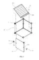
- FIG. 1 illustrates a three-dimensional view of the present invention.
- FIG. 2 illustrates a first exploded view of shelf of the present invention.
- FIG. 3 illustrates a first three-dimensional view of shelf of the present invention.
- FIG. 4 illustrates a schematic view of the connector of another embodiment in the present invention.
- FIG. 5 illustrates a schematic view of the connecting portion of the panel of another embodiment in the present invention.
- FIG. 6 illustrates three connecting portions on both sides of the panel in the present invention.
- FIG. 7 illustrates an exploded view of shelf of another embodiment in the present invention.
- FIG. 8 illustrates a schematic view of shelf of another embodiment in the present invention.
- FIG. 9 illustrates the shelf with a door in the present invention.
- FIG. 10 illustrates a schematic view of the shelf with the door in the present invention.
- FIG. 11 illustrates a schematic view of the shelf with the door in the present invention in another embodiment.
- FIG. 12 illustrates a first embodiment of a cabinet including a plurality of the shelves in the present invention.
- FIG. 13 illustrates a second embodiment of a cabinet including a plurality of the shelves in the present invention.
- FIG. 14 illustrates a third embodiment of a cabinet including a plurality of the shelves in the present invention.
- the interlayer structure of a shelf may includes a shelf 10 , having a plurality of connectors 11 and panels 12 , wherein both sides of the panels 12 have at least one connecting portion 121 and a connecting unit 13 .
- the connecting portion 121 on the panel 12 forms a U-shaped groove, and the connecting unit 13 has filled sealing structure in the center. Therefore, the connecting unit 13 can be disposed on both sides of the panels 12 through connecting portion 121 .
- the connecting unit 13 has a connecting groove 132 corresponding to the panel 12 . Furthermore, the connecting portion 121 of the connecting unit 13 forms a cross shape.
- shelf 10 has two storage space 15 by auxiliary panel 14 . It can make shelf 10 has two equal and parallel storage spaces 15 , moreover, it makes shelf 10 more adjustable, enhance the practicability, furthermore, the connecting unit 13 and the connecting groove 132 can form a T-shape with a single shelf 10 (Also referring to FIG. 4 ), so that shelf 10 will not have projection and is safe to use.
- the combination unit 121 corresponding to the both sides of panel 12 forms a convex spherical shape, and make combination unit 13 's center has hollow scarf joint part 131 , thereby composing scarf joint part 131 of connecting unit 13 and combination 121 , and utilizing the connecting groove 132 with auxiliary panel 14 to change the storage space of the shelf, which enhance its practicability.
- both sides of the panel 12 has 2-3 corresponding connecting portion 121 (Also referring to FIG. 6 ), and respectively provide connecting unit 13 to make the shelf 10 composed by panel 12 and connectors 11 can adjust auxiliary panel with its need, and increase the variability of storage space 15 of the shelf 10 .
- auxiliary panel 14 can have a swash plate structure, referring to FIG. 7-8 , both sides of the auxiliary panel 14 is bent parallel to the sealing structure 141 , and set a stopper part 142 on the side-end of sealing structure 141 .
- Side-end sealing structure 141 of auxiliary panel can joint on the connectors 11 of shelf 10
- another side-end sealing structure 141 can joint on connecting unit 13 of panel 12 . It can make auxiliary panel 14 form a swash plate structure in the shelf 10 , which can let user to put the shoes, the stopper part 142 set on the end of auxiliary panel 14 can restrict shoes to slip.
- the shelf 10 can set door 16 with connectors 11 , and the connecting unit 13 of panel 12 can joint with magnetic part 133 , which the connecting unit 13 will attract corresponding magnetic part 133 and make the door 16 close well.
- the connecting unit 13 has the same structure as connectors 11 (Also referring to FIG. 10 ), and the door 16 has the concave arc dodge for the assemblies 13 on both sides.
- Shelf 10 can utilize connectors 11 and connecting unit 13 to make composition, referring to FIG. 11-14 , it can compose a cabinet, and this cabinet can adjust its structure by the function needed.
- this cabinet can adjust its structure by the function needed.
- the variability of the adjustable shelf can enhance its practicability.
- the present invention set connecting portion 13 on both sides of panel 12 , and respectively provide connecting unit 13 to make the shelf 10 composed by panel 12 and connectors 11 can adjust auxiliary panel with its need, which can make shelf 10 have at least two storage space, and increase the variability of storage space 15 of the shelf 10 .
- interior auxiliary panels can increase the structural strength and enhance the stability of the structure.
Landscapes
- Assembled Shelves (AREA)
Abstract
Description
Claims (4)
Applications Claiming Priority (3)
| Application Number | Priority Date | Filing Date | Title |
|---|---|---|---|
| CN201320568347.7U CN203483087U (en) | 2013-09-13 | 2013-09-13 | Interlayer structure of combined type storage rack |
| CN201320568347.7 | 2013-09-13 | ||
| CN201320568347U | 2013-09-13 |
Publications (2)
| Publication Number | Publication Date |
|---|---|
| US20150076099A1 US20150076099A1 (en) | 2015-03-19 |
| US9445666B2 true US9445666B2 (en) | 2016-09-20 |
Family
ID=50253961
Family Applications (1)
| Application Number | Title | Priority Date | Filing Date |
|---|---|---|---|
| US14/482,713 Active US9445666B2 (en) | 2013-09-13 | 2014-09-10 | Shelf with interlayers |
Country Status (3)
| Country | Link |
|---|---|
| US (1) | US9445666B2 (en) |
| KR (1) | KR200483025Y1 (en) |
| CN (1) | CN203483087U (en) |
Cited By (9)
| Publication number | Priority date | Publication date | Assignee | Title |
|---|---|---|---|---|
| US10531735B1 (en) | 2018-09-26 | 2020-01-14 | Liberty Procurement Co. Inc. | Double storage shoe rack |
| US20220257008A1 (en) * | 2021-02-12 | 2022-08-18 | Frank Wei | Configurable Storage and Display Frame |
| US20220299052A1 (en) * | 2021-03-17 | 2022-09-22 | Steelcase Inc. | Clip fastener for privacy screen |
| US11668335B2 (en) * | 2011-03-28 | 2023-06-06 | Flooring Industries Limited, Sarl | Composed element and rear wall construction applied herewith |
| US11759009B1 (en) * | 2022-10-05 | 2023-09-19 | Ten Square Inc. | Storage box combination that is stacked up and down and is assembled left and right |
| USD1082510S1 (en) * | 2023-06-19 | 2025-07-08 | Sip Lizenz—Und Rechteverwaltungs | Flooring tile connector |
| US20250234993A1 (en) * | 2024-01-19 | 2025-07-24 | Jun LYU | Highly stable assembled cabinet |
| US12419423B2 (en) | 2023-03-09 | 2025-09-23 | Honda Motor Co., Ltd. | Coupling device and method for coupling panels |
| US12446680B2 (en) | 2023-03-09 | 2025-10-21 | Honda Motor Co., Ltd. | Wrap device for modular panel system and wrapping method |
Families Citing this family (15)
| Publication number | Priority date | Publication date | Assignee | Title |
|---|---|---|---|---|
| CN203483087U (en) * | 2013-09-13 | 2014-03-19 | 张文聪 | Interlayer structure of combined type storage rack |
| USD773293S1 (en) * | 2014-03-06 | 2016-12-06 | Mausoleum, S.A. De C.V. | Connector |
| KR101712494B1 (en) * | 2015-01-16 | 2017-03-22 | 주식회사 펀잇쳐스 | Kit for furniture |
| TWI595848B (en) * | 2016-09-06 | 2017-08-21 | yi-xing Huang | Diaphragm connection block and partition |
| USD830818S1 (en) * | 2017-09-19 | 2018-10-16 | University Of West Bohemia | Corner bracket |
| GB2567447A (en) | 2017-10-11 | 2019-04-17 | Catemario Di Quadri Francesco | Furniture Item |
| USD922862S1 (en) | 2018-01-29 | 2021-06-22 | Columbarium By Design, Llc | Niche bracket |
| USD891814S1 (en) * | 2018-05-01 | 2020-08-04 | Columbarium By Design, Llc | Niche cabinet |
| JP2020028641A (en) * | 2018-08-24 | 2020-02-27 | 政義 市瀬 | Assembly type display stand |
| USD931606S1 (en) * | 2019-10-21 | 2021-09-28 | Spectrum Diversified Designs, Llc | Basket |
| US10980341B1 (en) * | 2020-07-27 | 2021-04-20 | Gregory Allan Van Pelt | Beverage rack assembly and method of construction |
| USD1074415S1 (en) * | 2020-08-06 | 2025-05-13 | Pucksrus, Inc. | Puck |
| AU2021106607A4 (en) * | 2021-08-23 | 2021-11-11 | Peaple, Stephen MR | An Expandable Display Frame |
| WO2024152142A1 (en) * | 2023-01-16 | 2024-07-25 | 王翔承 | Combination piece group and combined frame thereof |
| ES3004183B2 (en) * | 2023-09-08 | 2025-12-16 | Univ Valladolid | MULTIFUNCTIONAL LECTOR |
Citations (20)
| Publication number | Priority date | Publication date | Assignee | Title |
|---|---|---|---|---|
| US1281856A (en) * | 1916-01-24 | 1918-10-15 | Slade & Miller Company | Toy blocks. |
| US3891335A (en) * | 1973-10-25 | 1975-06-24 | Continental Display Corp | Retaining clip |
| US3913289A (en) * | 1972-06-27 | 1975-10-21 | Bodo Recker | Connecting device for panel-shaped members |
| US3955510A (en) * | 1974-12-13 | 1976-05-11 | Mukerrem Kinik | Shelving apparatus |
| US4493425A (en) * | 1983-05-12 | 1985-01-15 | Tsukasa Yoshida | Rack assembly apparatus |
| US5121526A (en) * | 1990-08-15 | 1992-06-16 | Eugene R. Burkard | Interconnection clip for model structures |
| US5466057A (en) * | 1994-03-16 | 1995-11-14 | Blankenburg; Karl | Modular storage apparatus |
| US5715956A (en) * | 1995-10-30 | 1998-02-10 | Ns Planning Inc. | Joint for modular shelves and modular shelf system using the same |
| US6732858B1 (en) * | 2003-01-17 | 2004-05-11 | Shu-Mei Chang Ou | Shoe storage box |
| US20040131416A1 (en) * | 2003-01-03 | 2004-07-08 | Hang-Chi Wu | KD furniture adapter |
| US20040134869A1 (en) * | 1999-10-13 | 2004-07-15 | Seville Classics, Inc. | Modular storage assembly |
| USD506613S1 (en) * | 2003-08-16 | 2005-06-28 | Industrial Wine Products, Inc. | Configurable bin |
| USD555399S1 (en) * | 2006-08-02 | 2007-11-20 | Ritter Tsai | Storage cube |
| US20090020669A1 (en) * | 2007-07-17 | 2009-01-22 | Jeff Wang | Connector for a Simple Cabinet |
| US20090166356A1 (en) * | 2007-12-31 | 2009-07-02 | Chang-Ming Tsai | Connector for a Modular Storage Assembly |
| US20100277045A1 (en) * | 2009-04-29 | 2010-11-04 | DONIDO ENTERPRISE Co, Ltd. | Magnetic doorstop |
| US7963404B2 (en) * | 2009-05-05 | 2011-06-21 | Kuo-Wen Shang | Combined shoe rack |
| US8955928B2 (en) * | 2012-09-07 | 2015-02-17 | Donido Enterprise Co., Ltd. | Joining connectors and a rack using joining connectors |
| US20150069894A1 (en) * | 2013-09-12 | 2015-03-12 | Kuo Wen Shang | Adjustable Structure of Combination Cabinet |
| US20150076099A1 (en) * | 2013-09-13 | 2015-03-19 | Wen-Tsung Chang | Shelf with interlayers |
Family Cites Families (1)
| Publication number | Priority date | Publication date | Assignee | Title |
|---|---|---|---|---|
| KR200468887Y1 (en) * | 2011-11-25 | 2013-09-05 | 문종인 | Prefab showcase |
-
2013
- 2013-09-13 CN CN201320568347.7U patent/CN203483087U/en not_active Expired - Fee Related
-
2014
- 2014-09-10 US US14/482,713 patent/US9445666B2/en active Active
- 2014-09-11 KR KR2020140006658U patent/KR200483025Y1/en not_active Expired - Fee Related
Patent Citations (20)
| Publication number | Priority date | Publication date | Assignee | Title |
|---|---|---|---|---|
| US1281856A (en) * | 1916-01-24 | 1918-10-15 | Slade & Miller Company | Toy blocks. |
| US3913289A (en) * | 1972-06-27 | 1975-10-21 | Bodo Recker | Connecting device for panel-shaped members |
| US3891335A (en) * | 1973-10-25 | 1975-06-24 | Continental Display Corp | Retaining clip |
| US3955510A (en) * | 1974-12-13 | 1976-05-11 | Mukerrem Kinik | Shelving apparatus |
| US4493425A (en) * | 1983-05-12 | 1985-01-15 | Tsukasa Yoshida | Rack assembly apparatus |
| US5121526A (en) * | 1990-08-15 | 1992-06-16 | Eugene R. Burkard | Interconnection clip for model structures |
| US5466057A (en) * | 1994-03-16 | 1995-11-14 | Blankenburg; Karl | Modular storage apparatus |
| US5715956A (en) * | 1995-10-30 | 1998-02-10 | Ns Planning Inc. | Joint for modular shelves and modular shelf system using the same |
| US20040134869A1 (en) * | 1999-10-13 | 2004-07-15 | Seville Classics, Inc. | Modular storage assembly |
| US20040131416A1 (en) * | 2003-01-03 | 2004-07-08 | Hang-Chi Wu | KD furniture adapter |
| US6732858B1 (en) * | 2003-01-17 | 2004-05-11 | Shu-Mei Chang Ou | Shoe storage box |
| USD506613S1 (en) * | 2003-08-16 | 2005-06-28 | Industrial Wine Products, Inc. | Configurable bin |
| USD555399S1 (en) * | 2006-08-02 | 2007-11-20 | Ritter Tsai | Storage cube |
| US20090020669A1 (en) * | 2007-07-17 | 2009-01-22 | Jeff Wang | Connector for a Simple Cabinet |
| US20090166356A1 (en) * | 2007-12-31 | 2009-07-02 | Chang-Ming Tsai | Connector for a Modular Storage Assembly |
| US20100277045A1 (en) * | 2009-04-29 | 2010-11-04 | DONIDO ENTERPRISE Co, Ltd. | Magnetic doorstop |
| US7963404B2 (en) * | 2009-05-05 | 2011-06-21 | Kuo-Wen Shang | Combined shoe rack |
| US8955928B2 (en) * | 2012-09-07 | 2015-02-17 | Donido Enterprise Co., Ltd. | Joining connectors and a rack using joining connectors |
| US20150069894A1 (en) * | 2013-09-12 | 2015-03-12 | Kuo Wen Shang | Adjustable Structure of Combination Cabinet |
| US20150076099A1 (en) * | 2013-09-13 | 2015-03-19 | Wen-Tsung Chang | Shelf with interlayers |
Cited By (13)
| Publication number | Priority date | Publication date | Assignee | Title |
|---|---|---|---|---|
| US11668335B2 (en) * | 2011-03-28 | 2023-06-06 | Flooring Industries Limited, Sarl | Composed element and rear wall construction applied herewith |
| US12313106B2 (en) | 2011-03-28 | 2025-05-27 | Unilin, Bv | Composed element and rear wall construction applied herewith |
| US12018706B2 (en) | 2011-03-28 | 2024-06-25 | Unilin Bv | Composed element and rear wall construction applied herewith |
| US10531735B1 (en) | 2018-09-26 | 2020-01-14 | Liberty Procurement Co. Inc. | Double storage shoe rack |
| US11452372B2 (en) * | 2021-02-12 | 2022-09-27 | Frank Wei | Configurable storage and display frame |
| US20220257008A1 (en) * | 2021-02-12 | 2022-08-18 | Frank Wei | Configurable Storage and Display Frame |
| US20220299052A1 (en) * | 2021-03-17 | 2022-09-22 | Steelcase Inc. | Clip fastener for privacy screen |
| US12025176B2 (en) * | 2021-03-17 | 2024-07-02 | Steelcase Inc. | Clip fastener for privacy screen |
| US11759009B1 (en) * | 2022-10-05 | 2023-09-19 | Ten Square Inc. | Storage box combination that is stacked up and down and is assembled left and right |
| US12419423B2 (en) | 2023-03-09 | 2025-09-23 | Honda Motor Co., Ltd. | Coupling device and method for coupling panels |
| US12446680B2 (en) | 2023-03-09 | 2025-10-21 | Honda Motor Co., Ltd. | Wrap device for modular panel system and wrapping method |
| USD1082510S1 (en) * | 2023-06-19 | 2025-07-08 | Sip Lizenz—Und Rechteverwaltungs | Flooring tile connector |
| US20250234993A1 (en) * | 2024-01-19 | 2025-07-24 | Jun LYU | Highly stable assembled cabinet |
Also Published As
| Publication number | Publication date |
|---|---|
| CN203483087U (en) | 2014-03-19 |
| KR20150001233U (en) | 2015-03-23 |
| US20150076099A1 (en) | 2015-03-19 |
| KR200483025Y1 (en) | 2017-03-27 |
Similar Documents
| Publication | Publication Date | Title |
|---|---|---|
| US9445666B2 (en) | Shelf with interlayers | |
| EP3092416B1 (en) | Method of assembling a product | |
| USD896013S1 (en) | Drawer panel | |
| US8955928B2 (en) | Joining connectors and a rack using joining connectors | |
| CA2965708C (en) | Multi-pivot hinge | |
| ES2818798T3 (en) | Display unit for merchandise | |
| CN105873475A (en) | A furniture panel | |
| US10085556B2 (en) | Drawer cabinet provided with adjustable drawer assembly mode | |
| US20140319090A1 (en) | Expandable frame structure | |
| USD810792S1 (en) | Refrigerator cabinet | |
| US2675287A (en) | Locking key for adjoining cabinet units | |
| US20170188703A1 (en) | Reusable Piece of a Furniture | |
| CA2990049C (en) | Adjustable header for sliding doors and windows | |
| CN107788706A (en) | Baffle connecting block and baffle | |
| US20160227924A1 (en) | Rack assembly joint | |
| USD801729S1 (en) | Drawer cabinet | |
| US2824775A (en) | Locking key for adjoining cabinet units | |
| USD810793S1 (en) | Refrigerator cabinet | |
| US3567302A (en) | Sliding door cabinet construction | |
| EP2524627A1 (en) | A mirror with variable surface. | |
| CN104896293B (en) | Splicing assembly convenient to splice | |
| KR200482790Y1 (en) | Prefabricated laminated shelves | |
| JP6521647B2 (en) | Kitchen cabinet | |
| CN205078560U (en) | Combination sideboard connector | |
| TWM491389U (en) | Connector for combined shelves |
Legal Events
| Date | Code | Title | Description |
|---|---|---|---|
| STCF | Information on status: patent grant |
Free format text: PATENTED CASE |
|
| MAFP | Maintenance fee payment |
Free format text: PAYMENT OF MAINTENANCE FEE, 4TH YR, SMALL ENTITY (ORIGINAL EVENT CODE: M2551); ENTITY STATUS OF PATENT OWNER: SMALL ENTITY Year of fee payment: 4 |
|
| FEPP | Fee payment procedure |
Free format text: MAINTENANCE FEE REMINDER MAILED (ORIGINAL EVENT CODE: REM.); ENTITY STATUS OF PATENT OWNER: SMALL ENTITY |
|
| FEPP | Fee payment procedure |
Free format text: 7.5 YR SURCHARGE - LATE PMT W/IN 6 MO, SMALL ENTITY (ORIGINAL EVENT CODE: M2555); ENTITY STATUS OF PATENT OWNER: SMALL ENTITY |
|
| MAFP | Maintenance fee payment |
Free format text: PAYMENT OF MAINTENANCE FEE, 8TH YR, SMALL ENTITY (ORIGINAL EVENT CODE: M2552); ENTITY STATUS OF PATENT OWNER: SMALL ENTITY Year of fee payment: 8 |