US9443726B1 - Semiconductor process - Google Patents
Semiconductor process Download PDFInfo
- Publication number
- US9443726B1 US9443726B1 US14/656,733 US201514656733A US9443726B1 US 9443726 B1 US9443726 B1 US 9443726B1 US 201514656733 A US201514656733 A US 201514656733A US 9443726 B1 US9443726 B1 US 9443726B1
- Authority
- US
- United States
- Prior art keywords
- layer
- process according
- top surface
- semiconductor process
- dielectric layer
- Prior art date
- Legal status (The legal status is an assumption and is not a legal conclusion. Google has not performed a legal analysis and makes no representation as to the accuracy of the status listed.)
- Active
Links
Images


Classifications
-
- H—ELECTRICITY
- H10—SEMICONDUCTOR DEVICES; ELECTRIC SOLID-STATE DEVICES NOT OTHERWISE PROVIDED FOR
- H10D—INORGANIC ELECTRIC SEMICONDUCTOR DEVICES
- H10D64/00—Electrodes of devices having potential barriers
- H10D64/20—Electrodes characterised by their shapes, relative sizes or dispositions
- H10D64/27—Electrodes not carrying the current to be rectified, amplified, oscillated or switched, e.g. gates
- H10D64/311—Gate electrodes for field-effect devices
- H10D64/411—Gate electrodes for field-effect devices for FETs
- H10D64/511—Gate electrodes for field-effect devices for FETs for IGFETs
- H10D64/514—Gate electrodes for field-effect devices for FETs for IGFETs characterised by the insulating layers
-
- H—ELECTRICITY
- H01—ELECTRIC ELEMENTS
- H01L—SEMICONDUCTOR DEVICES NOT COVERED BY CLASS H10
- H01L21/00—Processes or apparatus adapted for the manufacture or treatment of semiconductor or solid state devices or of parts thereof
- H01L21/02—Manufacture or treatment of semiconductor devices or of parts thereof
- H01L21/02104—Forming layers
- H01L21/02107—Forming insulating materials on a substrate
- H01L21/02296—Forming insulating materials on a substrate characterised by the treatment performed before or after the formation of the layer
- H01L21/02318—Forming insulating materials on a substrate characterised by the treatment performed before or after the formation of the layer post-treatment
- H01L21/02362—Forming insulating materials on a substrate characterised by the treatment performed before or after the formation of the layer post-treatment formation of intermediate layers, e.g. capping layers or diffusion barriers
-
- H—ELECTRICITY
- H01—ELECTRIC ELEMENTS
- H01L—SEMICONDUCTOR DEVICES NOT COVERED BY CLASS H10
- H01L21/00—Processes or apparatus adapted for the manufacture or treatment of semiconductor or solid state devices or of parts thereof
- H01L21/02—Manufacture or treatment of semiconductor devices or of parts thereof
- H01L21/02104—Forming layers
- H01L21/02107—Forming insulating materials on a substrate
- H01L21/02225—Forming insulating materials on a substrate characterised by the process for the formation of the insulating layer
- H01L21/0226—Forming insulating materials on a substrate characterised by the process for the formation of the insulating layer formation by a deposition process
- H01L21/02263—Forming insulating materials on a substrate characterised by the process for the formation of the insulating layer formation by a deposition process deposition from the gas or vapour phase
- H01L21/02271—Forming insulating materials on a substrate characterised by the process for the formation of the insulating layer formation by a deposition process deposition from the gas or vapour phase deposition by decomposition or reaction of gaseous or vapour phase compounds, i.e. chemical vapour deposition
-
- H—ELECTRICITY
- H01—ELECTRIC ELEMENTS
- H01L—SEMICONDUCTOR DEVICES NOT COVERED BY CLASS H10
- H01L21/00—Processes or apparatus adapted for the manufacture or treatment of semiconductor or solid state devices or of parts thereof
- H01L21/02—Manufacture or treatment of semiconductor devices or of parts thereof
- H01L21/02104—Forming layers
- H01L21/02107—Forming insulating materials on a substrate
- H01L21/02296—Forming insulating materials on a substrate characterised by the treatment performed before or after the formation of the layer
- H01L21/02318—Forming insulating materials on a substrate characterised by the treatment performed before or after the formation of the layer post-treatment
- H01L21/02345—Forming insulating materials on a substrate characterised by the treatment performed before or after the formation of the layer post-treatment treatment by exposure to radiation, e.g. visible light
- H01L21/02354—Forming insulating materials on a substrate characterised by the treatment performed before or after the formation of the layer post-treatment treatment by exposure to radiation, e.g. visible light using a coherent radiation, e.g. a laser
-
- H—ELECTRICITY
- H01—ELECTRIC ELEMENTS
- H01L—SEMICONDUCTOR DEVICES NOT COVERED BY CLASS H10
- H01L21/00—Processes or apparatus adapted for the manufacture or treatment of semiconductor or solid state devices or of parts thereof
- H01L21/02—Manufacture or treatment of semiconductor devices or of parts thereof
- H01L21/04—Manufacture or treatment of semiconductor devices or of parts thereof the devices having potential barriers, e.g. a PN junction, depletion layer or carrier concentration layer
- H01L21/18—Manufacture or treatment of semiconductor devices or of parts thereof the devices having potential barriers, e.g. a PN junction, depletion layer or carrier concentration layer the devices having semiconductor bodies comprising elements of Group IV of the Periodic Table or AIIIBV compounds with or without impurities, e.g. doping materials
- H01L21/30—Treatment of semiconductor bodies using processes or apparatus not provided for in groups H01L21/20 - H01L21/26
- H01L21/31—Treatment of semiconductor bodies using processes or apparatus not provided for in groups H01L21/20 - H01L21/26 to form insulating layers thereon, e.g. for masking or by using photolithographic techniques; After treatment of these layers; Selection of materials for these layers
- H01L21/3205—Deposition of non-insulating-, e.g. conductive- or resistive-, layers on insulating layers; After-treatment of these layers
- H01L21/321—After treatment
- H01L21/32115—Planarisation
- H01L21/3212—Planarisation by chemical mechanical polishing [CMP]
-
- H—ELECTRICITY
- H01—ELECTRIC ELEMENTS
- H01L—SEMICONDUCTOR DEVICES NOT COVERED BY CLASS H10
- H01L21/00—Processes or apparatus adapted for the manufacture or treatment of semiconductor or solid state devices or of parts thereof
- H01L21/02—Manufacture or treatment of semiconductor devices or of parts thereof
- H01L21/04—Manufacture or treatment of semiconductor devices or of parts thereof the devices having potential barriers, e.g. a PN junction, depletion layer or carrier concentration layer
- H01L21/18—Manufacture or treatment of semiconductor devices or of parts thereof the devices having potential barriers, e.g. a PN junction, depletion layer or carrier concentration layer the devices having semiconductor bodies comprising elements of Group IV of the Periodic Table or AIIIBV compounds with or without impurities, e.g. doping materials
- H01L21/30—Treatment of semiconductor bodies using processes or apparatus not provided for in groups H01L21/20 - H01L21/26
- H01L21/324—Thermal treatment for modifying the properties of semiconductor bodies, e.g. annealing, sintering
-
- H—ELECTRICITY
- H01—ELECTRIC ELEMENTS
- H01L—SEMICONDUCTOR DEVICES NOT COVERED BY CLASS H10
- H01L22/00—Testing or measuring during manufacture or treatment; Reliability measurements, i.e. testing of parts without further processing to modify the parts as such; Structural arrangements therefor
- H01L22/10—Measuring as part of the manufacturing process
- H01L22/12—Measuring as part of the manufacturing process for structural parameters, e.g. thickness, line width, refractive index, temperature, warp, bond strength, defects, optical inspection, electrical measurement of structural dimensions, metallurgic measurement of diffusions
-
- H—ELECTRICITY
- H10—SEMICONDUCTOR DEVICES; ELECTRIC SOLID-STATE DEVICES NOT OTHERWISE PROVIDED FOR
- H10D—INORGANIC ELECTRIC SEMICONDUCTOR DEVICES
- H10D64/00—Electrodes of devices having potential barriers
- H10D64/01—Manufacture or treatment
- H10D64/017—Manufacture or treatment using dummy gates in processes wherein at least parts of the final gates are self-aligned to the dummy gates, i.e. replacement gate processes
-
- H—ELECTRICITY
- H10—SEMICONDUCTOR DEVICES; ELECTRIC SOLID-STATE DEVICES NOT OTHERWISE PROVIDED FOR
- H10D—INORGANIC ELECTRIC SEMICONDUCTOR DEVICES
- H10D64/00—Electrodes of devices having potential barriers
- H10D64/60—Electrodes characterised by their materials
- H10D64/66—Electrodes having a conductor capacitively coupled to a semiconductor by an insulator, e.g. MIS electrodes
- H10D64/68—Electrodes having a conductor capacitively coupled to a semiconductor by an insulator, e.g. MIS electrodes characterised by the insulator, e.g. by the gate insulator
- H10D64/691—Electrodes having a conductor capacitively coupled to a semiconductor by an insulator, e.g. MIS electrodes characterised by the insulator, e.g. by the gate insulator comprising metallic compounds, e.g. metal oxides or metal silicates
-
- H—ELECTRICITY
- H10—SEMICONDUCTOR DEVICES; ELECTRIC SOLID-STATE DEVICES NOT OTHERWISE PROVIDED FOR
- H10D—INORGANIC ELECTRIC SEMICONDUCTOR DEVICES
- H10D64/00—Electrodes of devices having potential barriers
- H10D64/60—Electrodes characterised by their materials
- H10D64/66—Electrodes having a conductor capacitively coupled to a semiconductor by an insulator, e.g. MIS electrodes
- H10D64/68—Electrodes having a conductor capacitively coupled to a semiconductor by an insulator, e.g. MIS electrodes characterised by the insulator, e.g. by the gate insulator
- H10D64/693—Electrodes having a conductor capacitively coupled to a semiconductor by an insulator, e.g. MIS electrodes characterised by the insulator, e.g. by the gate insulator the insulator comprising nitrogen, e.g. nitrides, oxynitrides or nitrogen-doped materials
-
- H10P14/6334—
-
- H10P14/6542—
-
- H10P14/6548—
-
- H10P52/403—
-
- H10P74/203—
-
- H10P74/23—
-
- H10P95/06—
-
- H10P95/90—
-
- H—ELECTRICITY
- H10—SEMICONDUCTOR DEVICES; ELECTRIC SOLID-STATE DEVICES NOT OTHERWISE PROVIDED FOR
- H10D—INORGANIC ELECTRIC SEMICONDUCTOR DEVICES
- H10D84/00—Integrated devices formed in or on semiconductor substrates that comprise only semiconducting layers, e.g. on Si wafers or on GaAs-on-Si wafers
- H10D84/01—Manufacture or treatment
- H10D84/0123—Integrating together multiple components covered by H10D12/00 or H10D30/00, e.g. integrating multiple IGBTs
- H10D84/0126—Integrating together multiple components covered by H10D12/00 or H10D30/00, e.g. integrating multiple IGBTs the components including insulated gates, e.g. IGFETs
- H10D84/0135—Manufacturing their gate conductors
-
- H—ELECTRICITY
- H10—SEMICONDUCTOR DEVICES; ELECTRIC SOLID-STATE DEVICES NOT OTHERWISE PROVIDED FOR
- H10D—INORGANIC ELECTRIC SEMICONDUCTOR DEVICES
- H10D84/00—Integrated devices formed in or on semiconductor substrates that comprise only semiconducting layers, e.g. on Si wafers or on GaAs-on-Si wafers
- H10D84/01—Manufacture or treatment
- H10D84/02—Manufacture or treatment characterised by using material-based technologies
- H10D84/03—Manufacture or treatment characterised by using material-based technologies using Group IV technology, e.g. silicon technology or silicon-carbide [SiC] technology
- H10D84/038—Manufacture or treatment characterised by using material-based technologies using Group IV technology, e.g. silicon technology or silicon-carbide [SiC] technology using silicon technology, e.g. SiGe
Definitions
- the present invention relates generally to a semiconductor process, and more specifically to a semiconductor process planarizing a dielectric layer by treating a shrinkable layer covering the dielectric layer.
- CMP chemical mechanical polishing
- the CMP process can be used to remove a topographical target of a thin film layer on a semiconductor wafer and to produce a wafer with both a regular and planar surface.
- slurry is provided in a surface subject to planarization, and a mechanical polishing process is performed on the surface of the wafer.
- the slurry includes chemical agents and abrasives.
- the chemical agents may be PH buffers, oxidants, surfactants or the like, and the abrasives may be silica, alumina, zirconium oxide, or the like.
- the chemical reactions evoked by the chemical agents and the abrasion between the wafer, the abrasives, and the polishing pad can planarize the surface of the wafer.
- the present invention provides a semiconductor process, which forms a shrinkable layer on a dielectric layer, and treats the shrinkable layer to have a flat top surface. Therefore, the dielectric layer can also have a flat top surface by planarizing the shrinkable layer to expose it.
- the present invention provides a semiconductor process including the following steps.
- a dielectric layer is formed on a substrate, wherein the dielectric layer has at least a dishing from a first top surface.
- a shrinkable layer is formed to cover the dielectric layer, wherein the shrinkable layer has a second top surface.
- a treatment process is performed to shrink a part of the shrinkable layer according to a topography of the second top surface, thereby flattening the second top surface.
- the present invention provides a semiconductor process, which forms a shrinkable layer directly on a dielectric layer having at least a dishing from a top surface, thereby the shrinkable layer also has a top surface having at least a dishing; then, performs a treatment process to flatten the top surface of the shrinkable layer according to its topography.
- the dielectric layer can have a flat top surface by planarizing the shrinkable layer until exposing the dielectric layer.
- FIG. 1 schematically depicts a flow chart of a semiconductor process according to an embodiment of the present invention.
- FIGS. 2-7 schematically depict cross-sectional views of a semiconductor process according to an embodiment of the present invention.
- FIG. 8 schematically depicts a cross-sectional view of a semiconductor process according to another embodiment of the present invention.
- FIG. 1 schematically depicts a flow chart of a semiconductor process according to an embodiment of the present invention.
- FIGS. 2-7 schematically depict cross-sectional views of a semiconductor process according to an embodiment of the present invention.
- Step S 1 of FIG. 1 forming a dielectric layer on a substrate, wherein the dielectric layer has at least a dishing from a first top surface.
- the dielectric layer on the substrate may include a non-metal layer or a metal layer, depending upon practical requirements.
- the dielectric layer is an inter-level dielectric layer, which has gates, especially for metal gates therein, but the present invention is not restricted to be applied in this situation.
- a substrate 110 is provided.
- the substrate 110 may include a semiconductor substrate, for example, a silicon substrate, an epitaxial silicon substrate, a silicon germanium substrate, a silicon carbide substrate or a silicon-on-insulator (SOI) substrate, or may include a non-semiconductor substrate such as a glass substrate, but this is not limited thereto.
- An isolation structure 10 may be formed in the substrate 110 to identify each active area.
- the isolation structure 10 may be a shallow trench isolation (STI) structure, which may be formed by a shallow trench isolation (STI) process, but it is not limited thereto.
- STI shallow trench isolation
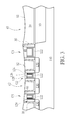
- Each of the metal gate structures G 1 /G 2 /G 3 may include a high-k gate dielectric layer 122 , a work function layer 124 , a barrier layer 126 , a gate electrode 128 and a spacer 129 . Also, a source/drain region 130 is disposed at two sides of each of the metal gate structures G 1 /G 2 /G 3 .
- the method of forming the metal gate structures G 1 /G 2 /G 3 may include, but not limited to, the following.
- Three sacrificial gates including high-k gate dielectric layers (not shown), sacrificial gate electrodes (not shown), cap layers (not shown) stacked from bottom to top are formed on the substrate 110 and the spacers 129 are formed beside the sacrificial gates; the source/drain region 130 is formed at two sides of each of the sacrificial gates in the substrate 110 ; and then, a dielectric layer (not shown) entirely covers the substrate 110 .
- a planarization process such as a chemical mechanical polishing/planarization (CMP) process, an etching process, or a combination of both, a portion of the dielectric layer is then removed to form the dielectric layer 20 .
- CMP chemical mechanical polishing/planarization
- the cap layers and the sacrificial gate electrodes are also completely removed to form gate trenches (not shown).
- a work function material layer (not shown), a barrier material layer (not shown), and a gate electrode material layer (not shown) are sequentially filled in the gate trenches, and a CMP process is carried out to form the work function layers 124 , the barrier layers 126 and the gate electrodes 128 .
- Some dishing (not shown) may occur due to above processes such as these CMP processes.
- the high-k gate dielectric layer 122 may include rare earth metal oxides or lanthanide oxides, such as hafnium oxide (HfO 2 ), hafnium silicon oxide (HfSiO 4 ), hafnium silicon oxynitride (HfSiON), aluminum oxide (Al 2 O 3 ), lanthanum oxide (La 2 O 3 ), lanthanum aluminum oxide (LaAlO), tantalum oxide (Ta 2 O 5 ), zirconium oxide (ZrO 2 ), zirconium silicon oxide (ZrSiO 4 ), hafnium zirconium oxide (HfZrO), yttrium oxide (Yb 2 O 3 ), yttrium silicon oxide (YbSiO), zirconium aluminate (ZrAlO), hafnium aluminate (HfAlO), aluminum nitride (AlN), titanium oxide (TiO 2 ), zirconium oxynitride (Hf
- the work function layer 124 and the barrier layer 126 may be formed through a physical vapor deposition (PVD) process, wherein the work function layer 124 may include a P type work function metal, such as a nitride of nickel (Ni), tungsten (W), molybdenum (Mo), tantalum (Ta), or titanium (Ti), or an N type work function metal, such as titanium aluminides (TiAl), aluminum zirconium (ZrAl), aluminum tungsten (WA 1 ), aluminum tantalum (TaAl) or aluminum hafnium (HfAl); and the barrier layer 126 may include Ti/titanium nitride (TiN) or Ta/tantalum nitride (TaN); the dielectric layer 20 may be an oxide layer, but is not limited thereto. People skilled in the art should realize that the metal gate structures G 1 /G 2 /G 3 of the present invention is not limited to be formed through the above-mentioned steps
- a contact etching stop layer (CESL) 30 may be formed on the substrate 110 to cover the sacrificial gates before the dielectric layer 20 is formed.
- the CESL 30 may include a monolayer structure or a multilayer structure, thereby providing required compressive stress or stretching stress to the metal gate structures G 1 /G 2 /G 3 .
- the CESL 30 may also be omitted.
- a lightly doped source/drain (LDD) region (not shown) may be formed in the substrate 100 before the spacer 129 is formed according to practical requirements.
- an etching back process is carried out to partially remove the work function layers 124 , the barrier layers 126 , and the gate electrodes 128 , to form trenches (not shown). Then, cap layers 40 are formed in the trenches on the work function layers 124 , the barrier layers 126 and the gate electrodes 128 , as shown in FIG. 3 .
- the cap layers 40 may be nitride layers or others.
- dishings d 1 and d 2 occur in a first top surface S 1 of the dielectric layer 20 and first top surfaces S 2 of the cap layers 40 .
- flat top surfaces are required to dispose metal interconnect structures on the dielectric layer 20 and the cap layers 40 in later processes.
- the number of the dishings d 1 and d 2 is not restricted to what is shown in the drawings.
- Step S 2 of FIG. 1 forming a shrinkable layer covering the dielectric layer, wherein the shrinkable layer has a second top surface.
- a shrinkable layer 50 blanketly covers the dielectric layer 20 and the cap layers 40 . Since the first top surface S 1 of the dielectric layer 20 and the first top surfaces S 2 of the cap layers 40 have dishings d 1 and d 2 , a second top surface S 3 of the shrinkable layer 50 inherently has dishings d 3 and d 4 as well.
- the shrinkable layer 50 may be an oxide layer, which may be preferably formed by a flowable chemical vapor deposition (FCVD) process.
- FCVD flowable chemical vapor deposition
- a thickness t 1 of the shrinkable layer 50 is larger than depths h 1 /h 2 of the dishings d 1 /d 2 , so that the dishings d 1 /d 2 can be full filled by the shrinkable layer 50 , and thus flat top surfaces of the dielectric layer 20 and the cap layers 40 can be obtained through later processes of the present invention.
- Step S 3 of FIG. 1 performing a treatment process to shrink a part of the shrinkable layer according to a topography of the second top surface, thereby flattening the second top surface.
- a treatment process P 1 may be performed to shrink at least a part of the shrinkable layer 50 . More precisely, a topography of the second top surface S 3 of the shrinkable layer 50 may be measured or obtained firstly, and the treatment process P 1 can be performed to shrink the part of the shrinkable layer 50 according to the topography.
- the topography of the second top surface S 3 may be measured by a white light interference method or an atomic force microscopy (AFM) method, but it is not limited thereto.
- the topography of the second top surface S 3 may be measured through scanning the second top surface S 3 with concentric circle paths, a spiral path, etc.
- the topography has relative high points k 1 /k 2 /k 3
- the treatment process P 1 may be performed on the relative high points k 1 /k 2 /k 3 only, to smoothen or flatten the topography, but it is not limited thereto.
- the treatment process P 1 may be performed on the whole second top surface S 3 of the shrinkable layer 50 to flatten the whole second top surface S 3 .
- the treatment process P 1 is a selective curing process, which may only cure a part of the second top surface S 3 of the shrinkable layer 50 or cure the whole second top surface S 3 of the shrinkable layer 50 with different curing forces.
- the treatment process P 1 is an annealing process.
- the treatment process P 1 is a laser beam annealing process, which is preferably capable of having a power distribution corresponding to every points of the whole second top surface S 3 , thereby the whole second top surface S 3 can be flattened accurately.
- the power distribution of the treatment process P 1 is a curve distribution of the power versus the second top surface S 3 of the shrinkable layer 50 , and the curve distribution of the power preferably covers the whole second top surface S 3 to have better flatness; in another embodiment, the power distribution of the treatment process P 1 is a point distribution, which only treats some points of the second top surface S 3 , thereby reducing processing costs, depending upon practical requirements.
- the shrinkable layer 50 ′ having a flat top surface S 4 can be obtained eventually, as shown in FIG. 6 . Then, the flat top surface S 4 can be transferred to the dielectric layer 20 and the cap layers 40 below as follows.
- Step S 4 of FIG. 1 performing a planarization process to planarize the shrinkable layer until the dielectric layer is exposed.
- a planarization process P 2 may be performed to remove a top part of the shrinkable layer 50 ′ until the dielectric layer 20 is exposed, thereby a flat top surface S 5 being obtained.
- parts 50 a / 50 b of the shrinkable layer 50 ′ still remain to fill the original dishings d 1 /d 2 of FIG. 3 , and thus constituting the flat top surface S 5 , but it is not limited thereto.
- FIG. 8 schematically depicts a cross-sectional view of a semiconductor process according to another embodiment of the present invention. As shown in FIG.
- a planarization process P 3 may be performed to remove all of the shrinkable layer 50 ′ and even a part of the dielectric layer 20 and the cap layers 40 to obtain a flat top surface S 6 , which is only constituted by the dielectric layer 20 and the cap layers 40 without having the shrinkable layer 50 ′ reserved.
- the planarization processes P 2 /P 3 may be chemical mechanical polishing (CMP) processes, wherein the planarization process P 3 has more over-polishing time to remove the shrinkable layer 50 ′, but it is not limited thereto.
- the present invention provides a semiconductor process, which forms a shrinkable layer directly on a dielectric layer having at least a dishing from a top surface, thereby the shrinkable layer also has a top surface having at least a dishing; then, performs a treatment process to flatten the top surface of the shrinkable layer according to its topography.
- the dielectric layer can have a flat top surface by planarizing the shrinkable layer to expose it.
- the shrinkable layer may be an oxide layer, which may be formed by a flowable chemical vapor deposition (FCVD) process.
- FCVD flowable chemical vapor deposition
- the topography of the top surface of the shrinkable layer may be measured by a white light interference method or an atomic force microscopy (AFM) method.
- the treatment process may be performed on some relative high points of the top surface of the shrinkable layer only, or may be performed on the whole shrinkable layer to flatten the whole top surface.
- the treatment process may be a selective curing process.
- the treatment process is an annealing process.
- the treatment process is a laser beam annealing process, which may have a power distribution corresponding to the whole top surface of the shrinkable layer.
- the power distribution may be a curve distribution of the power versus the top surface of the shrinkable layer, or may be a point distribution, which only treats some points of the top surface of the shrinkable layer.
- the shrinkable layer is planarized until the dielectric layer is exposed to get a flat top surface of the dielectric layer. In one case, a part of the shrinkable layer still remains to constitute a part of the flat top surface of the dielectric layer. In another case, all of the shrinkable layer is removed and a part of the dielectric layer may be removed as well to get the flat top surface of the dielectric layer.
Landscapes
- Engineering & Computer Science (AREA)
- Manufacturing & Machinery (AREA)
- Microelectronics & Electronic Packaging (AREA)
- Power Engineering (AREA)
- Physics & Mathematics (AREA)
- Computer Hardware Design (AREA)
- General Physics & Mathematics (AREA)
- Condensed Matter Physics & Semiconductors (AREA)
- Health & Medical Sciences (AREA)
- Optics & Photonics (AREA)
- Toxicology (AREA)
- Chemical & Material Sciences (AREA)
- Chemical Kinetics & Catalysis (AREA)
- Internal Circuitry In Semiconductor Integrated Circuit Devices (AREA)
- Mechanical Treatment Of Semiconductor (AREA)
Abstract
Description
Claims (20)
Priority Applications (2)
| Application Number | Priority Date | Filing Date | Title |
|---|---|---|---|
| US14/656,733 US9443726B1 (en) | 2015-03-13 | 2015-03-13 | Semiconductor process |
| US15/232,796 US20160351674A1 (en) | 2015-03-13 | 2016-08-09 | Semiconductor structure |
Applications Claiming Priority (1)
| Application Number | Priority Date | Filing Date | Title |
|---|---|---|---|
| US14/656,733 US9443726B1 (en) | 2015-03-13 | 2015-03-13 | Semiconductor process |
Related Child Applications (1)
| Application Number | Title | Priority Date | Filing Date |
|---|---|---|---|
| US15/232,796 Continuation US20160351674A1 (en) | 2015-03-13 | 2016-08-09 | Semiconductor structure |
Publications (2)
| Publication Number | Publication Date |
|---|---|
| US9443726B1 true US9443726B1 (en) | 2016-09-13 |
| US20160268125A1 US20160268125A1 (en) | 2016-09-15 |
Family
ID=56881449
Family Applications (2)
| Application Number | Title | Priority Date | Filing Date |
|---|---|---|---|
| US14/656,733 Active US9443726B1 (en) | 2015-03-13 | 2015-03-13 | Semiconductor process |
| US15/232,796 Abandoned US20160351674A1 (en) | 2015-03-13 | 2016-08-09 | Semiconductor structure |
Family Applications After (1)
| Application Number | Title | Priority Date | Filing Date |
|---|---|---|---|
| US15/232,796 Abandoned US20160351674A1 (en) | 2015-03-13 | 2016-08-09 | Semiconductor structure |
Country Status (1)
| Country | Link |
|---|---|
| US (2) | US9443726B1 (en) |
Cited By (1)
| Publication number | Priority date | Publication date | Assignee | Title |
|---|---|---|---|---|
| US9831133B2 (en) * | 2015-07-27 | 2017-11-28 | United Microelectronics Corp. | Semiconductor devices having metal gate and method for manufacturing semiconductor devices having metal gate |
Families Citing this family (2)
| Publication number | Priority date | Publication date | Assignee | Title |
|---|---|---|---|---|
| US10109627B2 (en) * | 2016-03-08 | 2018-10-23 | Taiwan Semiconductor Manufacturing Co., Ltd. | Enlarging spacer thickness by forming a dielectric layer over a recessed interlayer dielectric |
| CN109427668A (en) * | 2017-09-01 | 2019-03-05 | 中芯国际集成电路制造(上海)有限公司 | The manufacturing method of semiconductor device |
Citations (6)
| Publication number | Priority date | Publication date | Assignee | Title |
|---|---|---|---|---|
| US4415794A (en) | 1981-03-16 | 1983-11-15 | Fairchild Camera And Instrument Corporation | Laser scanning method for annealing, glass flow and related processes |
| US6368906B1 (en) * | 1997-09-12 | 2002-04-09 | Samsung Electronics Co., Ltd. | Method of planarization using selecting curing of SOG layer |
| US6399461B1 (en) * | 2001-01-16 | 2002-06-04 | Promos Technologies, Inc. | Addition of planarizing dielectric layer to reduce a dishing phenomena experienced during a chemical mechanical procedure used in the formation of shallow trench isolation regions |
| US7888273B1 (en) | 2006-11-01 | 2011-02-15 | Novellus Systems, Inc. | Density gradient-free gap fill |
| US20110312180A1 (en) * | 2010-06-21 | 2011-12-22 | Taiwan Semiconductor Manufacturing Company, Ltd. | Post cmp planarization by cluster ion beam etch |
| US20150118863A1 (en) * | 2013-10-25 | 2015-04-30 | Lam Research Corporation | Methods and apparatus for forming flowable dielectric films having low porosity |
-
2015
- 2015-03-13 US US14/656,733 patent/US9443726B1/en active Active
-
2016
- 2016-08-09 US US15/232,796 patent/US20160351674A1/en not_active Abandoned
Patent Citations (6)
| Publication number | Priority date | Publication date | Assignee | Title |
|---|---|---|---|---|
| US4415794A (en) | 1981-03-16 | 1983-11-15 | Fairchild Camera And Instrument Corporation | Laser scanning method for annealing, glass flow and related processes |
| US6368906B1 (en) * | 1997-09-12 | 2002-04-09 | Samsung Electronics Co., Ltd. | Method of planarization using selecting curing of SOG layer |
| US6399461B1 (en) * | 2001-01-16 | 2002-06-04 | Promos Technologies, Inc. | Addition of planarizing dielectric layer to reduce a dishing phenomena experienced during a chemical mechanical procedure used in the formation of shallow trench isolation regions |
| US7888273B1 (en) | 2006-11-01 | 2011-02-15 | Novellus Systems, Inc. | Density gradient-free gap fill |
| US20110312180A1 (en) * | 2010-06-21 | 2011-12-22 | Taiwan Semiconductor Manufacturing Company, Ltd. | Post cmp planarization by cluster ion beam etch |
| US20150118863A1 (en) * | 2013-10-25 | 2015-04-30 | Lam Research Corporation | Methods and apparatus for forming flowable dielectric films having low porosity |
Cited By (1)
| Publication number | Priority date | Publication date | Assignee | Title |
|---|---|---|---|---|
| US9831133B2 (en) * | 2015-07-27 | 2017-11-28 | United Microelectronics Corp. | Semiconductor devices having metal gate and method for manufacturing semiconductor devices having metal gate |
Also Published As
| Publication number | Publication date |
|---|---|
| US20160268125A1 (en) | 2016-09-15 |
| US20160351674A1 (en) | 2016-12-01 |
Similar Documents
| Publication | Publication Date | Title |
|---|---|---|
| CN105514105B (en) | Integrated circuit and forming method thereof | |
| US9685383B2 (en) | Method of forming semiconductor device | |
| US9685337B2 (en) | Method for fabricating semiconductor device | |
| US9159626B2 (en) | FinFET and fabricating method thereof | |
| US9281374B2 (en) | Metal gate structure and fabrication method thereof | |
| US9748144B1 (en) | Method of fabricating semiconductor device | |
| US9824931B2 (en) | Semiconductor device and method for fabricating the same | |
| US9570578B2 (en) | Gate and gate forming process | |
| US9583600B1 (en) | Semiconductor device and method for fabricating the same | |
| US8691652B2 (en) | Semiconductor process | |
| US20160104786A1 (en) | Semiconductor device and method for fabricating the same | |
| US9418853B1 (en) | Method for forming a stacked layer structure | |
| US9384985B2 (en) | Semiconductor structure including silicon and oxygen-containing metal layer and process thereof | |
| US9773887B2 (en) | Semiconductor device and method for fabricating the same | |
| US9530851B1 (en) | Semiconductor device and manufacturing methods thereof | |
| US20160071800A1 (en) | Semiconductor structure and process thereof | |
| US10290723B2 (en) | Semiconductor device with metal gate | |
| US9443726B1 (en) | Semiconductor process | |
| US8975666B2 (en) | MOS transistor and process thereof | |
| US20150206803A1 (en) | Method of forming inter-level dielectric layer | |
| KR101959626B1 (en) | Semiconductor arrangement and method of forming | |
| US9478628B1 (en) | Metal gate forming process | |
| TWI552209B (en) | Method of fabricating semiconductor device | |
| TWI536543B (en) | Metal gate structure and fabrication method thereof | |
| US9443952B2 (en) | Method of forming semiconductor device |
Legal Events
| Date | Code | Title | Description |
|---|---|---|---|
| AS | Assignment |
Owner name: UNITED MICROELECTRONICS CORP., TAIWAN Free format text: ASSIGNMENT OF ASSIGNORS INTEREST;ASSIGNORS:LI, KUN-JU;HUANG, PO-CHENG;LI, YU-TING;AND OTHERS;SIGNING DATES FROM 20150112 TO 20150312;REEL/FRAME:035156/0688 |
|
| STCF | Information on status: patent grant |
Free format text: PATENTED CASE |
|
| MAFP | Maintenance fee payment |
Free format text: PAYMENT OF MAINTENANCE FEE, 4TH YEAR, LARGE ENTITY (ORIGINAL EVENT CODE: M1551); ENTITY STATUS OF PATENT OWNER: LARGE ENTITY Year of fee payment: 4 |
|
| MAFP | Maintenance fee payment |
Free format text: PAYMENT OF MAINTENANCE FEE, 8TH YEAR, LARGE ENTITY (ORIGINAL EVENT CODE: M1552); ENTITY STATUS OF PATENT OWNER: LARGE ENTITY Year of fee payment: 8 |