US9438886B2 - Parallax scanning methods for stereoscopic three-dimensional imaging - Google Patents
Parallax scanning methods for stereoscopic three-dimensional imaging Download PDFInfo
- Publication number
- US9438886B2 US9438886B2 US13/639,330 US201113639330A US9438886B2 US 9438886 B2 US9438886 B2 US 9438886B2 US 201113639330 A US201113639330 A US 201113639330A US 9438886 B2 US9438886 B2 US 9438886B2
- Authority
- US
- United States
- Prior art keywords
- parallax
- stereoscopic
- view
- frame
- point
- Prior art date
- Legal status (The legal status is an assumption and is not a legal conclusion. Google has not performed a legal analysis and makes no representation as to the accuracy of the status listed.)
- Active, expires
Links
- 238000000034 method Methods 0.000 title claims abstract description 112
- 238000003384 imaging method Methods 0.000 title claims description 20
- 230000003287 optical effect Effects 0.000 claims description 30
- 230000001360 synchronised effect Effects 0.000 claims description 10
- 238000009877 rendering Methods 0.000 claims 1
- 210000000554 iris Anatomy 0.000 description 75
- 230000033001 locomotion Effects 0.000 description 30
- 230000000007 visual effect Effects 0.000 description 30
- 230000008447 perception Effects 0.000 description 27
- 241000282414 Homo sapiens Species 0.000 description 19
- 230000007246 mechanism Effects 0.000 description 18
- 230000008569 process Effects 0.000 description 17
- 238000000926 separation method Methods 0.000 description 15
- 210000004556 brain Anatomy 0.000 description 11
- 241000282412 Homo Species 0.000 description 9
- 238000004519 manufacturing process Methods 0.000 description 7
- 210000001525 retina Anatomy 0.000 description 7
- 210000002569 neuron Anatomy 0.000 description 6
- 230000004256 retinal image Effects 0.000 description 6
- 230000016776 visual perception Effects 0.000 description 6
- 230000008901 benefit Effects 0.000 description 5
- 239000003086 colorant Substances 0.000 description 5
- 238000011161 development Methods 0.000 description 5
- 230000018109 developmental process Effects 0.000 description 5
- 238000005516 engineering process Methods 0.000 description 5
- 238000012545 processing Methods 0.000 description 5
- 230000009471 action Effects 0.000 description 4
- 230000008859 change Effects 0.000 description 4
- 230000000694 effects Effects 0.000 description 4
- 230000006870 function Effects 0.000 description 4
- 230000004044 response Effects 0.000 description 4
- 230000002207 retinal effect Effects 0.000 description 4
- 238000013459 approach Methods 0.000 description 3
- 230000004438 eyesight Effects 0.000 description 3
- 230000004434 saccadic eye movement Effects 0.000 description 3
- 210000000857 visual cortex Anatomy 0.000 description 3
- 241001465754 Metazoa Species 0.000 description 2
- 230000004308 accommodation Effects 0.000 description 2
- 230000001149 cognitive effect Effects 0.000 description 2
- 230000003467 diminishing effect Effects 0.000 description 2
- 239000011521 glass Substances 0.000 description 2
- 210000003128 head Anatomy 0.000 description 2
- 238000013507 mapping Methods 0.000 description 2
- 210000001328 optic nerve Anatomy 0.000 description 2
- 238000010422 painting Methods 0.000 description 2
- 230000003252 repetitive effect Effects 0.000 description 2
- 238000012800 visualization Methods 0.000 description 2
- PXFBZOLANLWPMH-UHFFFAOYSA-N 16-Epiaffinine Natural products C1C(C2=CC=CC=C2N2)=C2C(=O)CC2C(=CC)CN(C)C1C2CO PXFBZOLANLWPMH-UHFFFAOYSA-N 0.000 description 1
- 241000272201 Columbiformes Species 0.000 description 1
- 241000282326 Felis catus Species 0.000 description 1
- 241000238631 Hexapoda Species 0.000 description 1
- 206010021403 Illusion Diseases 0.000 description 1
- 230000003044 adaptive effect Effects 0.000 description 1
- 208000003464 asthenopia Diseases 0.000 description 1
- 230000003190 augmentative effect Effects 0.000 description 1
- 230000004888 barrier function Effects 0.000 description 1
- 238000000576 coating method Methods 0.000 description 1
- 230000004456 color vision Effects 0.000 description 1
- 235000009508 confectionery Nutrition 0.000 description 1
- 230000001419 dependent effect Effects 0.000 description 1
- 238000013461 design Methods 0.000 description 1
- 230000004424 eye movement Effects 0.000 description 1
- 239000012530 fluid Substances 0.000 description 1
- 210000000873 fovea centralis Anatomy 0.000 description 1
- 238000001093 holography Methods 0.000 description 1
- 238000012986 modification Methods 0.000 description 1
- 230000004048 modification Effects 0.000 description 1
- 210000005036 nerve Anatomy 0.000 description 1
- 210000004126 nerve fiber Anatomy 0.000 description 1
- 230000003534 oscillatory effect Effects 0.000 description 1
- 230000002688 persistence Effects 0.000 description 1
- 230000035479 physiological effects, processes and functions Effects 0.000 description 1
- 230000010287 polarization Effects 0.000 description 1
- 238000007781 pre-processing Methods 0.000 description 1
- 230000009290 primary effect Effects 0.000 description 1
- 230000000750 progressive effect Effects 0.000 description 1
- 230000001711 saccadic effect Effects 0.000 description 1
- 238000012216 screening Methods 0.000 description 1
- 230000035807 sensation Effects 0.000 description 1
- 238000009416 shuttering Methods 0.000 description 1
- 238000001228 spectrum Methods 0.000 description 1
- 230000003068 static effect Effects 0.000 description 1
- 239000000126 substance Substances 0.000 description 1
- 238000012360 testing method Methods 0.000 description 1
- 230000009466 transformation Effects 0.000 description 1
- 238000013519 translation Methods 0.000 description 1
Images


Classifications
-
- H—ELECTRICITY
- H04—ELECTRIC COMMUNICATION TECHNIQUE
- H04N—PICTORIAL COMMUNICATION, e.g. TELEVISION
- H04N13/00—Stereoscopic video systems; Multi-view video systems; Details thereof
- H04N13/20—Image signal generators
- H04N13/204—Image signal generators using stereoscopic image cameras
- H04N13/239—Image signal generators using stereoscopic image cameras using two 2D image sensors having a relative position equal to or related to the interocular distance
-
- H04N13/0239—
-
- H04N13/0296—
-
- H—ELECTRICITY
- H04—ELECTRIC COMMUNICATION TECHNIQUE
- H04N—PICTORIAL COMMUNICATION, e.g. TELEVISION
- H04N13/00—Stereoscopic video systems; Multi-view video systems; Details thereof
- H04N13/20—Image signal generators
- H04N13/296—Synchronisation thereof; Control thereof
-
- H04N13/0246—
-
- H—ELECTRICITY
- H04—ELECTRIC COMMUNICATION TECHNIQUE
- H04N—PICTORIAL COMMUNICATION, e.g. TELEVISION
- H04N13/00—Stereoscopic video systems; Multi-view video systems; Details thereof
- H04N13/20—Image signal generators
- H04N13/204—Image signal generators using stereoscopic image cameras
- H04N13/246—Calibration of cameras
Definitions
- the presently disclosed embodiments relate to the psychophysics of human visual perception, stereoscopic imaging techniques and, more particularly, to systems and methods for capturing stereoscopic information from parallax scanning points of view.
- Visual perception is the interpretation by the brain of what the eyes see.
- Human brains have certain innate visual mechanisms to assist in process of perception. These mechanisms include a propensity to make certain assumptions about the images that are being seen based on limited information. Examples of this include certain human visual mechanisms having to do with recognition and object occlusion.
- Color displays also work in a comparable manner. Humans may be able to perceive millions of colors on a computer monitor, but the monitor itself produces only three particular colors, namely red, green, and blue. The illusion of additional colors are produced by presenting these three colors in a particular relationship to one another that exploits certain color visual perception mechanisms and thereby creating the illusion of a full spectrum of colors.
- Certain insects and animals determine relative spatial depth of a scene by simply moving one eye from side to side or up and down. A pigeon bobbing its head back and forth as it walks is a good example of this action.
- the oscillating eye movement presents motion parallax depth information over time. This allows for the determination of depth order by the relative movement of objects in the scene. Humans also possess the ability to process visual parallax information presented over time.
- the fundamentals of human sight are based on the fact that we have two eyes that look forward with visual fields that overlap.
- the eyes focus on an object by a means called accommodation. This function is performed simultaneously with a convergence of the eyes.
- Each eye records a two-dimensional image of the object from a slightly different point of view (or “parallax position”) on to the retinas.
- the two two-dimensional images are transmitted along the optical nerves to the brain's visual cortex and fused over time into a three-dimensional perception of the object through a process called stereopsis.
- stereopsis The object's three-dimensionality exists only in the brain—not in the eyes.
- Perception of three-dimensional space depends on various kinds of information in the scene being viewed including monocular cues and binocular cues, for example.
- Monocular cues include elements such as relative size, linear perspective, interposition, highlights, and shadows.
- Binocular cues include retinal disparity, accommodation, convergence, and learned cues including a familiarity with the subject matter. While all these factors may contribute to creating a perception of three-dimensional space in a scene, retinal disparity may provide one of the most important sources of information for creating a three-dimensional perception. Particularly, retinal disparity results in parallax information (i.e., an apparent change in the position, direction of motion, or other visual characteristics of an object caused by different observational positions) being supplied to the brain.
- parallax information i.e., an apparent change in the position, direction of motion, or other visual characteristics of an object caused by different observational positions
- each eye has a different observational position, each eye can provide a slightly different view of the same scene.
- the differences between the views represent parallax information that the brain can use to perceive three dimensional aspects of a scene.
- parallax there are several visual system sub-processes that also contribute to the mechanics of perception.
- Perception is an interpretation of the retinal image, not a description.
- a visual sensation becomes a perception by an unconscious association and interpretation of ideas held in memory.
- the visual order of perception is reflected by a learned knowledge of the environment that is based on subjective experience. This presents an ability to view the world with an understanding made possible by the processing of sensate experience into representations that have meaning. Intangible connections between stimulus and sensation are organized into signs that have meaning by corresponding to reality in a manner that is thought to be similar to the way words do in speech. This is because humans use all kinds of visual data provided by the two eyes via a series of sub-process to make a perception. Bits of visual data are assigned meaning and used to create a unified three-dimensional perception of the surrounding world. As humans encounter different forms of visual data through day-to-day experiences, new meanings and signs are developed to accommodate an on going perception.
- the human eyes are dynamic by their very nature.
- the eyes' gaze is never fixed or completely steady.
- the eyes are designed to constantly scan a scene to maintain and refresh the visual memory. This is, in part, due to the fundamental fact that the eyes are reasonably low resolution imagers.
- the function of the eyes in simple term is as follows: the retina is an area located at the rear of the eye on to which the eye's lens focuses an image.
- the retina is lined with specialized nerve cells called neurons that are light sensitive.
- the central region of the retina is called the fovea centralis or fovea.
- the fovea has the highest density neurons and therefore highest resolution. It is surrounded by several belts of neurons with diminishing density and therefore a diminishing resolution.
- the neurons that make up the retina feed information to the optic nerve which in turn connects to the visual cortex where an image perception takes place.
- Nearly 50% of the nerve fibers in the optic nerve carry information from the fovea, while the remaining 50% carry information from the neurons in the rest of the retina.
- the fovea comprises less than 1% of retinal area but the information it captures require as much as 50% of the brain's visual cortex to process. Humans maintain the perception of a sharp full field of view by constantly scanning the eyes and thereby the fovea a cross the scene being viewed.
- the human eye is continuously scanning although these actions are generally imperceptible. This scanning action is called a saccade.
- the saccade serves in part to refresh the image being cast onto the fovea and surrounding retina at the back of the eye.
- the simple mechanics of conventional stereoscopic imaging provides the following variables to place the position in depth of a scene object (with regard to the plane of the screen):
- stereoscopic display methods include stereoscopes, polarization, anaglyphic, Pulfrich, and shuttering technologies requiring the viewer to wear a special viewing apparatus such as glasses, for example.
- Autostereoscopic techniques such as holography, lenticular screens, and parallax barriers produce images with a three-dimensional illusion without the use of special glasses, but these methods generally require the use of a special screen.
- the present disclosure is directed to an alternative approach to three-dimensional imaging.
- the approach described herein is centered on the concept of presenting parallax three-dimensional information over time in a manner that exploits human short-term visual memory, depth mapping, and other sub-processing visual perceptual mechanisms.
- Parallax scanning and square-wave switching methods have been developed to exploit parallax over time in a manner that is compatible with conventional media systems.
- U.S. Pat. No. 5,991,551 discloses, inter alia, a method for a single camera to record images while undergoing a parallax scanning motion.
- the optical axis of a single camera is made to move in a repetitive pattern that causes the camera lens optical axis to be offset from a nominal stationary axis. This offset produces parallax information.
- the motion of the lens optical axis is referred to as parallax scanning. As the motion repeats over the pattern, the motion becomes oscillatory. At any particular instant, the motion may be described in terms of a parallax scan angle.
- Parallax scanning methods rely on discrete parallax differences between depth planes in a scene. The differences are caused by a parallax scan. When properly balanced (tuned) and displayed, the discrete parallax differences are perceived by the brain as depth.
- a parallax scan records a pattern of sequential parallax views on a single strip of film or digital media.
- the lens's optical axis sweeps in the plane of the nominal X and Y axes around the nominal optical Z axis, pivoting on the optical convergence point (out along the Z axis), so that it passes through positions having parallax in relation to the optical convergence point.
- the circular scanning of the lens's optical axis traces out a coaxial cone pattern with the convergence point as its apex.
- the scan pattern may be repeated with each cycle, or may change.
- the digital parallax scanner (DPS) iris scanning mechanism is disclosed in U.S. patent application Ser. No. 11/547,714.
- the assembly can be made of many different parts.
- One embodiment of the DPS employs two custom linear actuators and a central pivoting armature that holds the iris.
- the two parallel linear actuators have coordinated motion in such a way as to produce both x and y motions of the iris. For illustrative purposes think of the way a tank moves.
- the linear actuators consist of a moving coil and fixed magnetic yoke assembly, very similar to the typical actuator that controls the read/write heads in a computer hard drive.
- the entire scanner mechanism control system is completely digital.
- Parallax information may also be incorporated into computer generated images, as described in the aforementioned U.S. Pat. No. 6,324,347 (“the '347 patent”).
- the '347 patent discloses, inter alia, a method for computer generating parallax images using a virtual camera having a virtual lens.
- the parallax images may be generated by simulating a desired parallax scanning pattern of the lens aperture and employing, for example, a ray tracing algorithm to produce the images.
- the images may be stored in computer memory on a frame-by-frame basis.
- the images may be retrieved from memory for display on a computer monitor, recorded on video tape for display on a TV screen, and/or recorded on film for projection on a screen.
- the point of view of a camera e.g., the lens aperture
- the ray tracing method of image generation may be used to generate high quality computer images, such as those used in animated movies or special effects.
- This ray-tracing method may require large amounts of computation and can place a heavy burden on processing resources. Therefore, such a ray tracing method may be impractical for certain applications, such as 3D computer games, animation, and other graphics applications, which require quick response.
- the '257 patent discloses, inter alia, a method for parallax scanning through scene object position manipulation. Unlike the moving point of view methods taught in the '347 patent, the '257 patent teaches a fixed point of view, and scene objects are moved individually in a coordinated pattern to simulate a parallax scan. Even though the final images created using the '347 patent and the '257 patent may appear similar, the methods of generating these images are very different.
- U.S. Patent Application Publication No. 2006/0203335 teaches, inter alia, methods for critically aligning images with parallax differences for autostereoscopic display.
- the process requires two or more images of a subject volume with parallax differences and whose visual fields overlap in some portions of each of the images.
- a first image with an area of interest is critically aligned to a second image with the same area of interest but with a parallax difference.
- the images are aligned by means of a software viewer whereby the areas of interest are critically aligned along their translational and rotational axes to converge at some point.
- the historical and contemporary stereoscopic prior art teaches images captured from fixed (in the X horizontal axis) left and right points of view. Although disparity and convergence change, there is no provision for capture of sub-process visual information. Further, much of the parallax scanning, square-wave switching, and other parallax visualization prior art deals with capturing, simulating and/or presenting three-dimensional scenes in which objects and the environment are generally captured by a single camera lens (optical and/or virtual).
- the present invention is directed to overcoming one or more of the problems associated with two lens stereoscopic imaging methods.
- the presently disclosed embodiments may include the capability to capture non-horizontal parallax and other sub-process three-dimensional visual information in a manner that triggers a perceptional response that is not fatiguing to the viewer.
- stereoscopic parallax scanning can be used to simulate information captured by the eye's natural gaze and saccadic motions. This allows the combined stereoscopic (left and right views) display to present a variety of three-dimensional information to the viewer in a manner that will create a unified visual perception.
- One aspect of the invention is a method of using two parallax scanning points of view to capture left and right stereoscopic views for 3D display.
- the method includes establishing a right first parallax scanning point of view and field of view and a left second parallax scanning point of view. Both points of view are directed at a subject volume including a region of interest.
- the method includes reading at least one scene parameter associated with the field of view of the subject volume.
- the method includes determining parallax scan amplitudes, parallax scan pattern, parallax scan frequency, parallax scan direction(s), and/or the left and right stereoscopic disparity based on a value derived from at least one scene parameter.
- the method also includes generating and storing relevant metadata from said right and left parallax scanning points of view.
- the method includes displaying the recorded left and right parallax scanning point of view stereoscopically using conventional 3D projection or monitor displays. Additionally, one or more parallax scan parameters can be adjusted to trigger a sub-process perceptional response wherein the said region of interest appears realistically three-dimensional in all depth planes to a viewer on a standard 3D-aided display. Further, a single channel of the stereoscopic production can be distributed and displayed conventional 2D media as depth enhanced imagery.
- FIG. 1 is a flow chart representation of one parallax scanning stereoscopic image capture and display method according to an exemplary disclosed embodiment
- FIG. 2 is a diagrammatic representation of a converged stereoscopic camera layout method according to an exemplary disclosed embodiment
- FIG. 3 is a flow chart representation of an alternative parallax scanning stereoscopic image capture and display method according to an exemplary disclosed embodiment
- FIG. 3A is a diagrammatic representation of an orthogonal stereoscopic camera layout method according to an exemplary disclosed embodiment
- FIG. 4 is a diagrammatic representation of a circular clockwise parallax scanning iris method according to an exemplary disclosed embodiment
- FIG. 4A depicts an exemplary circular scan path including exemplary parallax scan positions and a table including exemplary path scan angles for frame rates of 24 and 30 frames per second.
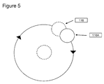
- FIG. 5 is a diagrammatic representation of the iris travel in one frame along a circular clockwise parallax scan path segment according to an exemplary disclosed embodiment
- FIG. 5A is a diagrammatic representation of multiple parallax scan path patterns and arrangements according to an exemplary disclosed embodiment
- FIG. 6 is a diagrammatic representation of each frame in one cycle of two parallax scanning irises configured for circular clockwise 4.36 Hz synchronous image capture at 24 frames per second according to an exemplary disclosed embodiment
- FIG. 7 is a diagrammatic representation of each frame in one cycle of two parallax scanning irises configured for circular left clockwise and right counter clockwise 4.36 Hz synchronous image capture at 24 frames per second according to an exemplary disclosed embodiment
- FIG. 8 is a diagrammatic representation of each frame in one cycle of two parallax scanning irises configured for circular left clockwise and right counter clockwise 4.36 Hz 180 degree out of phase image capture at 24 frames per second according to an exemplary disclosed embodiment
- FIG. 9 is a diagrammatic representation of each frame in one ellipse (cat's eye) cycle of two parallax scanning irises configured for left clockwise and right counter clockwise 4.36 Hz synchronous image capture at 24 frames per second according to an exemplary disclosed embodiment;
- the present disclosure relates to the stereoscopic imaging using parallax scanning points of view.
- stereoscopic refers to traditional left/right 3D imaging techniques and methods.
- parallax scanning refers the capture or generation and presentation over time of parallax data in a manner that exploits sub-process visual perceptional mechanism and will appear three-dimensional when viewed on conventional, unaided displays and enhances the three-dimensionality of stereoscopic displays.
- Parallax visualization refers to a form of autostereoscopic display that exploits certain (sub-process) short-term visual memory and depth mapping psychophysical visual mechanisms associated with human depth perception.
- FIG. 1 provides a flow chart representation of a two-parallax-scanning-points-of-view stereoscopic image capture and display method according to an exemplary disclosed embodiment.
- Flow chart 100 outlines first steps in image capture using converged parallax scanning points of view (POV) of the presently disclosed embodiment.
- Step 101 includes the selection of a region of interest within the subject volume.
- Step 102 includes the selection of the direction of view
- step 103 includes the selection of the field of view.
- the field of view is typically determined by the focal length of the capture lens and format of the image capture sensor.
- Step 104 includes establishing the first point of view. After a first point of view is determined, which establishes a zero (0) position and view plane. Step 105 reads and stores (as relevant metadata) a scene parameter(s) to determine initial left/right stereoscopic disparity which is subsequently set in Step 106 .
- Scene parameters are metrics like lens focal length, focus distance, distance from closest object to sensor, sensor motion velocity, and other data. The data derived from the scene metrics can be applied to an algorithm(s) like those disclosed, inter alia, by Mayhew et al PCT/US2010/021627 to determine stereoscopic disparity Step 106 and point of convergence Step 109 .
- Step 106 establishes the 107 left and 108 right points of view which are placed 90 degrees tangential to Step 104 zero point of view axis along which point of convergence 109 is established at intersection of Left 107 and Right 108 axes.
- Step 110 parallax scan amplitude, scan path pattern, scan direction(s), and scan frequency are among other things determined.
- Step 110 can be performed manually by eye or automatically using an algorithm(s) reading the metrics provided by Step 106 and values established in Steps 107 - 109 .
- Steps 106 , 109 and 110 can also be dynamic and constantly change values based on metrics received from Step 105 .
- Disparity, convergence and parallax scan parameters can be linked and driven by values derived from an algorithm(s) as previously referenced.
- Recording Steps 111 and 112 are elementary and can be accomplished by any number of methods available using traditional means like motion picture film, videotape, and/or digitally using digital storage devices.
- Step 113 includes any production or postproduction process and image formatting technique that is accomplished to create a final parallax scanning stereoscopic image product.
- Step 114 is the act of displaying the final parallax scanning stereoscopic image product using any appropriate 3D display means. It should be noted that Steps 101 to 114 can include a live broadcast television production workflow.
- FIG. 2 is a diagrammatic representation of a converged stereoscopic camera layout method according to an exemplary disclosed embodiment.
- the method represented by FIG. 2 is generally similar to the general stereoscopic method outlined by the flow chart of FIG. 1 .
- a center axis 1 is selected as a reference for establishing the view of an area of interest 11 and for determining the disparity between POV 4 L and the POV 4 R.
- Disparity distance D 1 can be determined by a scene parameter (e.g. distance from view plane 2 to area of interest 11 ) using an algorithm(s) that will also derive point of convergence.
- FIG. 3 provides a flow chart 100 A representation of a two-parallax-scanning-point-of-view stereoscopic image capture and display method according to an exemplary disclosed embodiment that is similar to the methods of FIG. 1 Flow Chart 100 .
- Flow Chart 100 A departs from the Flow Chart 100 method in that Steps 107 L and 108 R establish orthogonal points of view that are recorded by Steps 111 and 112 .
- the establishing of a parallax scan setting Step 110 is the same as in Flow Chart 100 .
- Step 113 includes the process of converging the images captured from the 107 L and 108 R points of view by using a pixel translation or using an affine transformation process to bring a desired point in both images into a critical alignment using methods like those disclosed by, inter alia, Martin et al in U.S. Patent Application Publication No. 2006/0203335.
- the advantage of capturing the 107 L and 108 R points of view orthographically is that the left and right image convergence (Step 113 ) can be easily adjusted electronically after the views are recorded or dynamically while the images are being captured as in the case of live television.
- the process of convergence adjustment can be dynamic and driven by an algorithm reading scene parameters or as a result the action in the scene being recorded.
- Step 113 A After convergence is set any production or postproduction process can accomplished at Step 113 A and image formatting technique can be applied to create a final parallax scanning stereoscopic image product.
- Step 114 is the act of displaying the final parallax scanning stereoscopic image product using any appropriate 3D display means. It should be noted that Flow Chart 100 A Steps 101 to 114 can also include a live broadcast television production workflow.
- FIG. 3A is a diagrammatic representation of an orthogonal stereoscopic camera layout method according to an exemplary disclosed embodiment.
- Item 11 in is the region of interest.
- the first point of view axis is represented by Item 1 .
- the disparity is the distance between 4 L and 4 R along view plane 2 .
- FIGS. 2 and 3A represent two basic stereoscopic camera layouts that are common in the industry. It is also common to use camera mounting systems that incorporate a folded optical path. Such configurations generally employ a beamsplitter at a 45 degree angle that allows the cameras to be configured at 90 degrees to one another, but capture images as if they were side-by-side albeit one camera sees a mirror image. For purposes of parallax scanning side-by-side or folded optical path mounting means are treated the same.
- FIG. 4 illustrates the basic operation.
- Item 128 represents the full aperture of a fully open iris of any given lens.
- Item 115 represents an iris setting approximately four f/stops smaller located at the center of the lens aperture.
- a parallax scanning iris 116 is offset some distance 115 A from the lens center by some amplitude. The iris 116 scans through positions of parallax in a clockwise direction along a circular scan path 117 .
- parallax position When the lens iris is moved off the center of the lens it sees a different point of view at the plane (i.e. parallax position) of focus.
- the amount the iris can be offset from the lens center is determined by the speed of the lens (maximum full iris) and the current iris setting.
- a parallax scanning lens can not scan at full iris. It is a hole moving inside another hole. If both holes are the same size there is nowhere to move. Parallax scanning functions best with lenses that are f/2.8 or faster and shooting iris is f/5.6 or smaller. However, parallax scanning can be quite effective at close focus with an f/stop that is one stop below full aperture.
- parallax scanning iris typically scans along a scan path at speeds of between 3 to 6 Hz. Empirical evidence suggests that the ideal scan frequency is 4.3 Hz. In order to trigger the appropriate visual psychophysical sub-process, parallax scan information should ideally be presented to the eye by the display at 4.3 Hz.
- a parallax scanning iris is constantly in motion.
- FIG. 5 illustrates this concept.
- the iris travels along scan path 117 from position 116 to 116 A some distance during sensor image capture interval.
- the continuous movement introduces an element of motion blur that is centered on a point in the center of the plane of focus.
- the amount of object blur is zero at the plane of focus and increases in amount as positions move forward and away from the point of focus.
- Parallax scan motion blur is very subtle and is directly dependent on the parallax scan amplitude, point of focus, image capture frame rate, the shutter angle, and exposure rate.
- a parallax scan path is the route and pattern the iris travels frame-by-frame as it scans through a cycle inside the full lens aperture.
- the scan path can be a variety of different shapes and sizes depending on what is required by the operator. Simple shapes are used to set up a pattern that the iris can cycle through over and over again as the sensor captures image frames. Ordinarily in most parallax scanning applications the scan path is a circle, but additional patterns are also possible.
- FIG. 5A illustrates four examples. In Example 1, iris 138 travels in a clockwise direction along an oval scan path 118 set at 45 degrees to the image vertical Y axis.
- Example 2 illustrates a random clockwise scan path 119 .
- Example 3 illustrates a simple vertical scan path 120 that provides for a reciprocating up and down motion for iris 138 .
- Example 4 illustrates a large f/stop iris traveling along a slightly oval scan path 121 .
- Stereoscopic parallax scanning provides a stereographer with a variety of sub-process visual information capture tools with which to create a unified three-dimensional perception.
- the tools include, but are not limited to the following:
- FIG. 6 illustrates a left and right parallax scan imaging sequence covering six frames.
- the left and right iris positions are indicated for each of six progressive frames in a left/right stereoscopic sequence.
- the positions represent the iris' set at smaller stop (say f/8) traveling along circular synchronous clockwise paths at 4.3 Hz that are contained in two lenses attached to sensors capturing images at 24 fps.
- FIG. 6 illustrates two parallax scanning lenses operating in a synchronous manner at 4.3 Hz with an f/8 iris setting scanning at an amplitude of approximately 75% of the full lens aperture.
- the iris position of each lens for every frame in the cycle is as follows:
- Frame 1 L depicts the left lens iris position for the first frame in a 5.6 frame clockwise circular parallax scan path cycle
- Frame 1 R depicts the right lens iris position for the first frame in a 5.6 frame clockwise circular parallax scan path cycle
- Frame 2 L depicts the left lens iris position for the second frame in a 5.6 frame clockwise circular parallax scan path cycle
- Frame 2 R depicts the right lens iris position for the second frame in a 5.6 frame clockwise circular parallax scan path cycle
- Frame 3 L depicts the left lens iris position for the third frame in a 5.6 frame clockwise circular parallax scan path cycle
- Frame 3 R depicts the right lens iris position for the third frame in a 5.6 frame clockwise circular parallax scan path cycle
- Frame 4 L depicts the left lens iris position for the forth frame in a 5.6 frame clockwise circular parallax scan path cycle
- Frame 4 R depicts the right lens iris position for the forth frame in a 5.6 frame clockwise circular parallax scan path cycle
- Frame 5 L depicts the left lens iris position for the fifth frame in a 5.6 frame clockwise circular parallax scan path cycle
- Frame 5 R depicts the right lens iris position for the fifth frame in a 5.6 frame clockwise circular parallax scan path cycle
- Frame 6 L depicts the left lens iris position for the last 0.6 frame in a 5.6 frame clockwise circular parallax scan path cycle
- Frame 6 R depicts the right lens iris position for the last 0.6 frame in a 5.6 frame clockwise circular parallax scan path cycle
- FIG. 7 illustrates two parallax scanning lenses operating in a synchronous left clockwise master right counter clockwise mirror opposite manner at 4.3 Hz with an approximation of an f/8 iris setting scanning at an amplitude approximation of a 75% of the full lens aperture.
- the iris position of each lens for every frame in the cycle is as follows:
- Frame 1 L depicts the left lens iris position for the first frame in a 5.6 frame clockwise circular parallax scan path cycle
- Frame 1 R depicts the right lens iris position for the first frame in a 5.6 frame counter clockwise circular parallax scan path cycle
- Frame 2 L depicts the left lens iris position for the second frame in a 5.6 frame clockwise circular parallax scan path cycle
- Frame 2 R depicts the right lens iris position for the second frame in a 5.6 frame counter clockwise circular parallax scan path cycle
- Frame 3 L depicts the left lens iris position for the third frame in a 5.6 frame clockwise circular parallax scan path cycle
- Frame 3 R depicts the right lens iris position for the third frame in a 5.6 frame counter clockwise circular parallax scan path cycle
- Frame 4 L depicts the left lens iris position for the forth frame in a 5.6 frame clockwise circular parallax scan path cycle
- Frame 4 R depicts the right lens iris position for the forth frame in a 5.6 frame counter clockwise circular parallax scan path cycle
- Frame 5 L depicts the left lens iris position for the fifth frame in a 5.6 frame clockwise circular parallax scan path cycle
- Frame 5 R depicts the right lens iris position for the fifth frame in a 5.6 frame counter clockwise circular parallax scan path cycle
- Frame 6 L depicts the left lens iris position for the last 0.6 frame in a 5.6 frame clockwise circular parallax scan path cycle
- Frame 6 R depicts the right lens iris position for the last 0.6 frame in a 5.6 frame counter clockwise circular parallax scan path cycle
- FIG. 8 illustrates two parallax scanning lenses operating in a synchronous left clockwise master right counter clockwise 180 degree out of phase opposite manner at 4.3 Hz with an approximation of an f/8 iris setting scanning at an amplitude approximation of 75% of the full lens aperture.
- the iris position of each lens for every frame in the cycle is as follows:
- Frame 1 L depicts the left lens iris position for the first frame in a 5.6 frame clockwise circular parallax scan path cycle
- Frame 1 R depicts the right lens iris position for the first frame in a 5.6 frame counter clockwise 180 degrees out of phase circular parallax scan path cycle
- Frame 2 L depicts the left lens iris position for the second frame in a 5.6 frame clockwise circular parallax scan path cycle
- Frame 2 R depicts the right lens iris position for the second frame in a 5.6 frame counter clockwise 180 degrees out of phase circular parallax scan path cycle
- Frame 3 L depicts the left lens iris position for the third frame in a 5.6 frame clockwise circular parallax scan path cycle
- Frame 3 R depicts the right lens iris position for the third frame in a 5.6 frame counter clockwise 180 degrees out of phase circular parallax scan path cycle
- Frame 4 L depicts the left lens iris position for the forth frame in a 5.6 frame clockwise circular parallax scan path cycle
- Frame 4 R depicts the right lens iris position for the forth frame in a 5.6 frame counter clockwise 180 degrees out of phase circular parallax scan path cycle
- Frame 5 L depicts the left lens iris position for the fifth frame in a 5.6 frame clockwise circular parallax scan path cycle
- Frame 5 R depicts the right lens iris position for the fifth frame in a 5.6 frame counter clockwise 180 degrees out of phase circular parallax scan path cycle
- Frame 6 L depicts the left lens iris position for the last 0.6 frame in a 5.6 frame clockwise circular parallax scan path cycle
- Frame 6 R depicts the right lens iris position for the last 0.6 frame in a 5.6 frame counter clockwise 180 degrees out of phase circular parallax scan path cycle
- FIG. 9 illustrates two parallax scanning lenses operating in a synchronous left clockwise master right counter clockwise mirror opposite manner at 4.3 Hz with an approximation of an f/8 iris setting scanning on an elliptical vertically oriented scan path produced by a variable amplitude in the full lens aperture
- the methods detailed above can also be applied to synthetically generated stereoscopic imagery.
- the methods are substantially the same as in live-action imagery.
- a center point is selected as a reference for establishing the view of area of interest and also for determining the polar coordinates for the placement of the parallax scan points of view.
- Each point of view is determined, for example, by the separation (radius), the scan frequency, the current frame count, and the frame rate.
- the geometry of the scan path is typically elliptical or circular but can also include other geometries depending on the requirements of a particular application.
- the scan path may be random, algorithmic, or even determined by some external function like a sound source. Assuming the parallax scan path is a perfect circle, each successive point of view will have a constant angular separation defined as:
- the progression of the polar coordinates of parallax scan points of view may be accomplished by assigning the first parallax scan position to the chosen initial angle and radius. Subsequent positions may be determined by adding a constant separation angle to the current position while maintaining a constant radius (or half separation).
- the polar coordinates for a particular frame in a sequence may be defined, for example, as:
- the offset distance S for each parallax scan position can be determined by a scene parameter, such as a distance d c , in a manner similar to the square-wave methods discussed above.
- Each parallax scan position may be offset by value S from center point 11 and located in its proper position along the parallax scan path.
- FIG. 5 illustrates the polar positions of a 4 Hz parallax scan at 24 frames per second. Shown in FIG. 5 is the center point 11 along with six points of view (POV 1 . . . POV 6 ). Each point of view is offset from the center point 11 by an offset distance S.
- parallax view positions can be calculated.
- the primary effect from parallax depth-enhancement comes from the choice of the offset or view separation.
- a smaller view separation corresponds to a convergence point (apparent scene depth where there is no visible pixel motion from one frame to the next) that is closer to the camera, while a larger view separation corresponds to a convergence point that is farther from the camera.
- This is the inverse of the pixel separation, which is the number of pixels to shift each image to critically align them at the chosen convergence point.
- a smaller pixel separation corresponds to a convergence point that is farther from the camera, while a larger pixel separation corresponds to a convergence point that is closer to the camera.
- any suitable computing device any of today's modern computers can be configured with appropriate software for executing the computational and display techniques described above. These methods may also be accomplished as part of a pre-processing or predetermined processing routine the results of which may be configured for later display on a user screen. Alternatively, or additionally, the described methods of generating and critically aligning images according to any of the methods described above may be accomplished in real-time or in near real-time by the viewer.
Landscapes
- Engineering & Computer Science (AREA)
- Multimedia (AREA)
- Signal Processing (AREA)
- Testing, Inspecting, Measuring Of Stereoscopic Televisions And Televisions (AREA)
Abstract
Description
-
- Information in the retinal image may be interpreted in many different ways. Because we begin with ambiguous information, we cannot make deductions from the retinal image, only inferences . . . we have learned that the visual system succeeds in interpreting images because of statistical regularities present in the visual environment and hence in the retinal image. These regularities permit the visual system to use fragmentary information present in the retinal image to draw accurate inferences about the physical cause of the image. For example, when we make inferences from the retinal image, the knowledge that we live in a three-dimensional world is essential to the correct interpretation of the image. Often, we are made aware of the existence of these powerful interpretations and their assumptions when they are in error, that is, when we discover a visual illusion.
- 1. Rock, I. The Logic of Perception. Cambridge, Mass.: MIT Press, 1985.
- 2. Churchland, P. et al. The Computational Brain. Cambridge, Mass.: MIT Press, 1992.
- 3. Tomlin, P. “Maintaining the Three-dimensional Illusion.” Information Display, Dec. 1987:11-14
- 4. Ogle, K. N. “Some Aspects of Stereoscopic Depth Perception.” Journal of the Optical Society of America 57, no. 9 (1967): 1073-1081.
- 5. Marr, D. Vision. San Francisco: W. H. Freeman, 1982.
- 6. Jones, E. et al. “Visual Image Depth Enhancement by Parallax Induction.” Advances in Display Technology IV, SPIE Proceedings. Society of Photo-Optical Instrumentation Engineers, 1984. 16.
- 7. McLaurin, A. P. et al. “Visual Image Depth Enhancement Process: An Approach to Three-Dimensional Imaging.”
Displays 7, no. 3 (1986): 112. - 8. Mayhew, C. A. “Texture and Depth Enhancement for Motion Pictures and Television.”
SMPTE Journal 9, no. 10 (1990): 809-814. - 9. Mayhew, C. A. “True 3-Dimensional Broadcast Television without Glasses.” NAB Engineering Proceedings. Altanta, 1990. 478. (revised version)
- 10. Mayhew, C. A. “Vision III Single-Camera Autostereoscopic Methods.” SMTPE Journal 100 (1991): 411-416.
- Mayhew, C. A. “A 35 mm Autostereoscopic System for Live-Action Imaging Using a Single Camera and Lens.” SMTPE Journal 102 (1993): 505-511.
- 12. Mayhew, C. A. “Parallax Scanning Using a Single Lens.” SPIE Stereoscopic Displays and Vitrual Reality Systems III Proceedings. San Jose, 1996.154-160.
- 13. Proffitt, D. et al. “Perceived depth is enhanced with parallax scanning.” University of Virginia—Cognitive Science Department, March 1999.
- 14. Subramanian, A. et al. “Segmentation and Range Sensing Using a Moving-Aperture Lens.” Proceedings of the 8th IEEE International Conference on Computer Vision (ICCV 2001). Vancouver, 2001.500-507.
- 15. Mayhew, C. A. et al. “Three-dimensional visualization of geographical terrain data using temporal parallax difference induction.” Proc. of SPIE-IS&T Electronic Imaging, SPIE Vol. 7240, 72401H, San Jose, Calif., 2009
- 16. Serrano-Pedraza, P. et al. “Stereo vision requires an explicit encoding of vertical disparity.” Journal of Vision, 9 (4):3. 1-13, Apr. 3, 2009.
- 17. Farell, B. “Orientation-Specific Computation in Stereoscopic Vision.” The Journal of Neuroscience, Sep. 6, 2006-26(36):9090-9106
- 18. Teichert, T. et al “Depth perception during saccades.” Journal of Vision, 8(14):27, 1-13, Dec. 23, 2008.
- 19. Pylyshyn, Z. W. “Seeing and Visualizing” Massachusetts Institute of Technology 2003.
-
- Disparity between the two points of view (also known as interocular distance or IO)
- Point of convergence of the two optical axis
An object's spatial position relative to the plane of the screen is determined by the amount of disparity and point of convergence. When the point of convergence is set behind an object in the foreground, the distance that the point of convergence is set behind that object and the amount of disparity between the two points of convergence will determine how far in front of the surface of the screen the object will be projected. The focal length of the lens and format of the capture medium will effect afore mentioned stereoscopic variables, but only in the amount required to achieve the same result.
Three-Dimensional Imaging
24/4.3=5.6
-
- 360 degrees/cycle*scan frequency (cycles/second)/frame rate (frames/second)
For example, a scan frequency of 4.4 Hz and a frame rate of 30 frames per second gives an angular separation of 360*4.4/30=52.8 degrees.
- 360 degrees/cycle*scan frequency (cycles/second)/frame rate (frames/second)
-
- (frame number*separation angle+initial angle, radius)
Here, the frame number counts from 0, the initial angle is determined by the situation or the requirements of the user, the separation angle is as defined as above, and the radius is the same as the half separation defined earlier. These polar coordinates may also be expressed as a Cartesian coordinate vector. For example, given a set of polar coordinates (angle, radius), and, assuming clockwise rotation with an angle of 0 aligned with the y-axis, one can calculate Cartesian coordinates (x,y) as (radius*sin(angle), radius*cos(angle)). A table illustrating the parallax scan polar angles for each frame for both 24 and 30 frames per second playback is provided inFIG. 4A .
- (frame number*separation angle+initial angle, radius)
Claims (16)
Priority Applications (1)
| Application Number | Priority Date | Filing Date | Title |
|---|---|---|---|
| US13/639,330 US9438886B2 (en) | 2010-04-07 | 2011-04-07 | Parallax scanning methods for stereoscopic three-dimensional imaging |
Applications Claiming Priority (3)
| Application Number | Priority Date | Filing Date | Title |
|---|---|---|---|
| US32186210P | 2010-04-07 | 2010-04-07 | |
| US13/639,330 US9438886B2 (en) | 2010-04-07 | 2011-04-07 | Parallax scanning methods for stereoscopic three-dimensional imaging |
| PCT/US2011/031568 WO2011127273A1 (en) | 2010-04-07 | 2011-04-07 | Parallax scanning methods for stereoscopic three-dimensional imaging |
Publications (2)
| Publication Number | Publication Date |
|---|---|
| US20130113891A1 US20130113891A1 (en) | 2013-05-09 |
| US9438886B2 true US9438886B2 (en) | 2016-09-06 |
Family
ID=44146654
Family Applications (1)
| Application Number | Title | Priority Date | Filing Date |
|---|---|---|---|
| US13/639,330 Active 2033-03-13 US9438886B2 (en) | 2010-04-07 | 2011-04-07 | Parallax scanning methods for stereoscopic three-dimensional imaging |
Country Status (2)
| Country | Link |
|---|---|
| US (1) | US9438886B2 (en) |
| WO (1) | WO2011127273A1 (en) |
Cited By (2)
| Publication number | Priority date | Publication date | Assignee | Title |
|---|---|---|---|---|
| US9959671B1 (en) | 2018-01-18 | 2018-05-01 | Scandy, LLC | System and method for capturing, processing and rendering data through a template-driven processing pipeline |
| US20190253607A1 (en) * | 2018-02-15 | 2019-08-15 | Qualcomm Incorporated | Object tracking autofocus |
Families Citing this family (14)
| Publication number | Priority date | Publication date | Assignee | Title |
|---|---|---|---|---|
| US9124877B1 (en) * | 2004-10-21 | 2015-09-01 | Try Tech Llc | Methods for acquiring stereoscopic images of a location |
| US9113074B2 (en) * | 2010-12-22 | 2015-08-18 | Olympus Corporation | Imaging apparatus, imaging method, and computer readable storage medium for applying special effects processing to an automatically set region of a stereoscopic image |
| US8754929B1 (en) * | 2011-05-23 | 2014-06-17 | John Prince | Real time vergence control for 3D video capture and display |
| JP5412692B2 (en) * | 2011-10-04 | 2014-02-12 | 株式会社モルフォ | Image processing apparatus, image processing method, image processing program, and recording medium |
| US9165401B1 (en) | 2011-10-24 | 2015-10-20 | Disney Enterprises, Inc. | Multi-perspective stereoscopy from light fields |
| US9113043B1 (en) * | 2011-10-24 | 2015-08-18 | Disney Enterprises, Inc. | Multi-perspective stereoscopy from light fields |
| US20130293547A1 (en) * | 2011-12-07 | 2013-11-07 | Yangzhou Du | Graphics rendering technique for autostereoscopic three dimensional display |
| US10133470B2 (en) * | 2012-10-09 | 2018-11-20 | Samsung Electronics Co., Ltd. | Interfacing device and method for providing user interface exploiting multi-modality |
| KR20150000649A (en) * | 2013-06-25 | 2015-01-05 | 삼성전자주식회사 | Apparatus and method for providing information about broadcasting image |
| CN104010178B (en) * | 2014-06-06 | 2017-01-04 | 深圳市墨克瑞光电子研究院 | Binocular image parallax adjustment method and device and binocular camera |
| WO2018189853A1 (en) | 2017-04-13 | 2018-10-18 | オリンパス株式会社 | Stereoscopic endoscope optical system and endoscope provided therewith |
| WO2018211595A1 (en) | 2017-05-16 | 2018-11-22 | オリンパス株式会社 | Optical system for stereoscopic viewing and imaging device equipped with same |
| WO2019008618A1 (en) * | 2017-07-03 | 2019-01-10 | オリンパス株式会社 | Stereoscopic optical system and imaging device provided therewith |
| WO2019064515A1 (en) | 2017-09-29 | 2019-04-04 | オリンパス株式会社 | Stereoscopic optical system and imaging device equipped with same |
Citations (8)
| Publication number | Priority date | Publication date | Assignee | Title |
|---|---|---|---|---|
| US5510831A (en) | 1994-02-10 | 1996-04-23 | Vision Iii Imaging, Inc. | Autostereoscopic imaging apparatus and method using suit scanning of parallax images |
| US6324347B1 (en) | 1993-11-05 | 2001-11-27 | Vision Iii Imaging, Inc. | Autostereoscopic imaging apparatus and method using a parallax scanning lens aperture |
| US20020131170A1 (en) * | 2001-01-12 | 2002-09-19 | Bryan Costales | Stereoscopic aperture valves |
| US20050253924A1 (en) * | 2004-05-13 | 2005-11-17 | Ken Mashitani | Method and apparatus for processing three-dimensional images |
| US20070147671A1 (en) * | 2005-12-22 | 2007-06-28 | Eastman Kodak Company | Analyzing radiological image using 3D stereo pairs |
| US20080002201A1 (en) * | 2006-07-03 | 2008-01-03 | Fujifilm Corporation | High-speed polarizing device and high-speed birefringence measuring apparatus and stereoscopic image display apparatus utilizing the polarizing device |
| US20080178232A1 (en) * | 2007-01-18 | 2008-07-24 | Verizon Data Services Inc. | Method and apparatus for providing user control of video views |
| US20090074398A1 (en) * | 2004-04-09 | 2009-03-19 | Vision Iii Imaging, Inc. | Optical Element Parallax Scanning Device |
Family Cites Families (9)
| Publication number | Priority date | Publication date | Assignee | Title |
|---|---|---|---|---|
| US4966436A (en) | 1987-04-30 | 1990-10-30 | Christopher A. Mayhew | Apparatus for obtaining images for use in displaying a three-dimensional |
| US4815819A (en) | 1987-04-30 | 1989-03-28 | Christopher A. Mayhew | Method for obtaining images for use in displaying a three-dimensional illusion and related image recording medium |
| US5157484A (en) | 1989-10-23 | 1992-10-20 | Vision Iii Imaging, Inc. | Single camera autosteroscopic imaging system |
| US5014126A (en) | 1989-10-23 | 1991-05-07 | Vision Iii Imaging, Inc. | Method and apparatus for recording images with a single image receiver for autostereoscopic display |
| US5444479A (en) | 1993-09-02 | 1995-08-22 | Vision Iii Imaging, Inc. | Single camera autostereoscopic imaging apparatus |
| US6734900B2 (en) | 1997-11-13 | 2004-05-11 | Christopher Mayhew | Real time camera and lens control system for image depth of field manipulation |
| EP1425707A4 (en) | 2001-07-06 | 2008-08-06 | Vision Iii Imaging Inc | Image segmentation by means of temporal parallax difference induction |
| EP1570683A1 (en) | 2002-11-21 | 2005-09-07 | Vision III Imaging, Inc. | Critical alignment of parallax images for autostereoscopic display |
| ATE433590T1 (en) | 2002-11-27 | 2009-06-15 | Vision Iii Imaging Inc | SAMPLING PARALLAX BY MANIPULATION OF THE POSITION OF OBJECTS IN A SCENE |
-
2011
- 2011-04-07 US US13/639,330 patent/US9438886B2/en active Active
- 2011-04-07 WO PCT/US2011/031568 patent/WO2011127273A1/en not_active Ceased
Patent Citations (8)
| Publication number | Priority date | Publication date | Assignee | Title |
|---|---|---|---|---|
| US6324347B1 (en) | 1993-11-05 | 2001-11-27 | Vision Iii Imaging, Inc. | Autostereoscopic imaging apparatus and method using a parallax scanning lens aperture |
| US5510831A (en) | 1994-02-10 | 1996-04-23 | Vision Iii Imaging, Inc. | Autostereoscopic imaging apparatus and method using suit scanning of parallax images |
| US20020131170A1 (en) * | 2001-01-12 | 2002-09-19 | Bryan Costales | Stereoscopic aperture valves |
| US20090074398A1 (en) * | 2004-04-09 | 2009-03-19 | Vision Iii Imaging, Inc. | Optical Element Parallax Scanning Device |
| US20050253924A1 (en) * | 2004-05-13 | 2005-11-17 | Ken Mashitani | Method and apparatus for processing three-dimensional images |
| US20070147671A1 (en) * | 2005-12-22 | 2007-06-28 | Eastman Kodak Company | Analyzing radiological image using 3D stereo pairs |
| US20080002201A1 (en) * | 2006-07-03 | 2008-01-03 | Fujifilm Corporation | High-speed polarizing device and high-speed birefringence measuring apparatus and stereoscopic image display apparatus utilizing the polarizing device |
| US20080178232A1 (en) * | 2007-01-18 | 2008-07-24 | Verizon Data Services Inc. | Method and apparatus for providing user control of video views |
Non-Patent Citations (2)
| Title |
|---|
| International Search Report from the European Patent Office for International Application No. PCT/US2011/031568, mailed Jul. 1, 2011. |
| Mayhew, C. A. et al., "Three-Dimensional Visualization of Geographical Terrain Data Using Temporal Paraflax Difference Induction," Proceedings of SPIE-The International Society for Optical Engineering-Proceedings of SPIE-IS and T Electronic Imaging-Human Vision and Electronic Imaging XIV 2009, SPIE, vol. 7240, pp. 72401H-1 to 72401H-11, XP-002576988, (2009). |
Cited By (2)
| Publication number | Priority date | Publication date | Assignee | Title |
|---|---|---|---|---|
| US9959671B1 (en) | 2018-01-18 | 2018-05-01 | Scandy, LLC | System and method for capturing, processing and rendering data through a template-driven processing pipeline |
| US20190253607A1 (en) * | 2018-02-15 | 2019-08-15 | Qualcomm Incorporated | Object tracking autofocus |
Also Published As
| Publication number | Publication date |
|---|---|
| WO2011127273A1 (en) | 2011-10-13 |
| US20130113891A1 (en) | 2013-05-09 |
Similar Documents
| Publication | Publication Date | Title |
|---|---|---|
| US9438886B2 (en) | Parallax scanning methods for stereoscopic three-dimensional imaging | |
| Fehn et al. | Interactive 3-DTV-concepts and key technologies | |
| Fuchs et al. | Immersive 3D telepresence | |
| JP4635403B2 (en) | Stereoscopic image creation method and apparatus | |
| US9460555B2 (en) | System and method for three-dimensional visualization of geographical data | |
| CN100483463C (en) | System and method for rendering 3-D images on a 3-d image display screen | |
| Zilly et al. | Production rules for stereo acquisition | |
| KR101013086B1 (en) | Parallax scanning system and method through position manipulation of scene object | |
| Hill et al. | 3-D liquid crystal displays and their applications | |
| US20160344999A1 (en) | SYSTEMS AND METHODs FOR PRODUCING PANORAMIC AND STEREOSCOPIC VIDEOS | |
| CN108141578A (en) | Camera is presented | |
| US20130128014A1 (en) | System for stereoscopically viewing motion pictures | |
| KR100274624B1 (en) | Apparatus for 3D image generator using accumulative liquid display | |
| KR20160098589A (en) | Photographing and Displaying Apparatus for Hologram 3-Dimensional Image | |
| JP4975256B2 (en) | 3D image presentation device | |
| KR101192121B1 (en) | Method and apparatus for generating anaglyph image using binocular disparity and depth information | |
| Kang Wei et al. | Three-dimensional scene navigation through anaglyphic panorama visualization | |
| TWI572899B (en) | Augmented reality imaging method and system | |
| CN100382110C (en) | Image Processing | |
| Hill | Scalable multi-view stereo camera array for real world real-time image capture and three-dimensional displays | |
| WO2017141139A1 (en) | A method for image transformation | |
| Benna | Systems and Practices to Produce Stereoscopic Space on Screen | |
| Devernay | Image and geometry processing for 3-D cinematography | |
| Rastogi et al. | StereoCam3D (An Android App. That Lets You Capture Realtime 3D Pics And Videos) | |
| Watt et al. | 3D media and the human visual system |
Legal Events
| Date | Code | Title | Description |
|---|---|---|---|
| AS | Assignment |
Owner name: VISION III IMAGING, INC., VIRGINIA Free format text: ASSIGNMENT OF ASSIGNORS INTEREST;ASSIGNORS:MAYHEW, CHRISTOPHER A.;MAYHEW, CRAIG M.;REEL/FRAME:029482/0509 Effective date: 20121217 |
|
| STCF | Information on status: patent grant |
Free format text: PATENTED CASE |
|
| AS | Assignment |
Owner name: ECKHART G. GROHMANN REVOCABLE TRUST OF 1985, WISCO Free format text: SECURITY INTEREST;ASSIGNOR:VISION III IMAGING, INC.;REEL/FRAME:043309/0125 Effective date: 20160815 |
|
| FEPP | Fee payment procedure |
Free format text: MAINTENANCE FEE REMINDER MAILED (ORIGINAL EVENT CODE: REM.); ENTITY STATUS OF PATENT OWNER: LARGE ENTITY |
|
| FEPP | Fee payment procedure |
Free format text: SURCHARGE FOR LATE PAYMENT, LARGE ENTITY (ORIGINAL EVENT CODE: M1554); ENTITY STATUS OF PATENT OWNER: LARGE ENTITY |
|
| MAFP | Maintenance fee payment |
Free format text: PAYMENT OF MAINTENANCE FEE, 4TH YEAR, LARGE ENTITY (ORIGINAL EVENT CODE: M1551); ENTITY STATUS OF PATENT OWNER: LARGE ENTITY Year of fee payment: 4 |
|
| FEPP | Fee payment procedure |
Free format text: MAINTENANCE FEE REMINDER MAILED (ORIGINAL EVENT CODE: REM.); ENTITY STATUS OF PATENT OWNER: LARGE ENTITY |
|
| FEPP | Fee payment procedure |
Free format text: 7.5 YR SURCHARGE - LATE PMT W/IN 6 MO, LARGE ENTITY (ORIGINAL EVENT CODE: M1555); ENTITY STATUS OF PATENT OWNER: LARGE ENTITY |
|
| MAFP | Maintenance fee payment |
Free format text: PAYMENT OF MAINTENANCE FEE, 8TH YEAR, LARGE ENTITY (ORIGINAL EVENT CODE: M1552); ENTITY STATUS OF PATENT OWNER: LARGE ENTITY Year of fee payment: 8 |