US9434258B2 - Power converter with diagnostic unit power supply output - Google Patents
Power converter with diagnostic unit power supply output Download PDFInfo
- Publication number
- US9434258B2 US9434258B2 US13/653,003 US201213653003A US9434258B2 US 9434258 B2 US9434258 B2 US 9434258B2 US 201213653003 A US201213653003 A US 201213653003A US 9434258 B2 US9434258 B2 US 9434258B2
- Authority
- US
- United States
- Prior art keywords
- coupled
- power converter
- positive
- vehicle
- switch
- Prior art date
- Legal status (The legal status is an assumption and is not a legal conclusion. Google has not performed a legal analysis and makes no representation as to the accuracy of the status listed.)
- Expired - Fee Related, expires
Links
- 239000003990 capacitor Substances 0.000 claims abstract description 23
- 239000000446 fuel Substances 0.000 claims description 47
- 238000012360 testing method Methods 0.000 claims description 11
- 238000002405 diagnostic procedure Methods 0.000 claims description 7
- 238000000034 method Methods 0.000 claims description 4
- 230000008878 coupling Effects 0.000 claims description 3
- 238000010168 coupling process Methods 0.000 claims description 3
- 238000005859 coupling reaction Methods 0.000 claims description 3
- 238000010586 diagram Methods 0.000 description 4
- 230000001133 acceleration Effects 0.000 description 3
- 239000002283 diesel fuel Substances 0.000 description 2
- UFHFLCQGNIYNRP-UHFFFAOYSA-N Hydrogen Chemical compound [H][H] UFHFLCQGNIYNRP-UHFFFAOYSA-N 0.000 description 1
- QVGXLLKOCUKJST-UHFFFAOYSA-N atomic oxygen Chemical compound [O] QVGXLLKOCUKJST-UHFFFAOYSA-N 0.000 description 1
- 230000005540 biological transmission Effects 0.000 description 1
- 238000002485 combustion reaction Methods 0.000 description 1
- 238000003487 electrochemical reaction Methods 0.000 description 1
- 239000001257 hydrogen Substances 0.000 description 1
- 229910052739 hydrogen Inorganic materials 0.000 description 1
- 238000004519 manufacturing process Methods 0.000 description 1
- 239000000463 material Substances 0.000 description 1
- 238000012986 modification Methods 0.000 description 1
- 230000004048 modification Effects 0.000 description 1
- 239000001301 oxygen Substances 0.000 description 1
- 229910052760 oxygen Inorganic materials 0.000 description 1
- 230000001172 regenerating effect Effects 0.000 description 1
Images


Classifications
-
- B—PERFORMING OPERATIONS; TRANSPORTING
- B60—VEHICLES IN GENERAL
- B60L—PROPULSION OF ELECTRICALLY-PROPELLED VEHICLES; SUPPLYING ELECTRIC POWER FOR AUXILIARY EQUIPMENT OF ELECTRICALLY-PROPELLED VEHICLES; ELECTRODYNAMIC BRAKE SYSTEMS FOR VEHICLES IN GENERAL; MAGNETIC SUSPENSION OR LEVITATION FOR VEHICLES; MONITORING OPERATING VARIABLES OF ELECTRICALLY-PROPELLED VEHICLES; ELECTRIC SAFETY DEVICES FOR ELECTRICALLY-PROPELLED VEHICLES
- B60L3/00—Electric devices on electrically-propelled vehicles for safety purposes; Monitoring operating variables, e.g. speed, deceleration or energy consumption
- B60L3/0023—Detecting, eliminating, remedying or compensating for drive train abnormalities, e.g. failures within the drive train
- B60L3/0053—Detecting, eliminating, remedying or compensating for drive train abnormalities, e.g. failures within the drive train relating to fuel cells
-
- B60L11/1803—
-
- B60L11/1868—
-
- B60L11/1885—
-
- B60L11/1887—
-
- B—PERFORMING OPERATIONS; TRANSPORTING
- B60—VEHICLES IN GENERAL
- B60L—PROPULSION OF ELECTRICALLY-PROPELLED VEHICLES; SUPPLYING ELECTRIC POWER FOR AUXILIARY EQUIPMENT OF ELECTRICALLY-PROPELLED VEHICLES; ELECTRODYNAMIC BRAKE SYSTEMS FOR VEHICLES IN GENERAL; MAGNETIC SUSPENSION OR LEVITATION FOR VEHICLES; MONITORING OPERATING VARIABLES OF ELECTRICALLY-PROPELLED VEHICLES; ELECTRIC SAFETY DEVICES FOR ELECTRICALLY-PROPELLED VEHICLES
- B60L3/00—Electric devices on electrically-propelled vehicles for safety purposes; Monitoring operating variables, e.g. speed, deceleration or energy consumption
- B60L3/04—Cutting off the power supply under fault conditions
-
- B—PERFORMING OPERATIONS; TRANSPORTING
- B60—VEHICLES IN GENERAL
- B60L—PROPULSION OF ELECTRICALLY-PROPELLED VEHICLES; SUPPLYING ELECTRIC POWER FOR AUXILIARY EQUIPMENT OF ELECTRICALLY-PROPELLED VEHICLES; ELECTRODYNAMIC BRAKE SYSTEMS FOR VEHICLES IN GENERAL; MAGNETIC SUSPENSION OR LEVITATION FOR VEHICLES; MONITORING OPERATING VARIABLES OF ELECTRICALLY-PROPELLED VEHICLES; ELECTRIC SAFETY DEVICES FOR ELECTRICALLY-PROPELLED VEHICLES
- B60L50/00—Electric propulsion with power supplied within the vehicle
- B60L50/50—Electric propulsion with power supplied within the vehicle using propulsion power supplied by batteries or fuel cells
- B60L50/51—Electric propulsion with power supplied within the vehicle using propulsion power supplied by batteries or fuel cells characterised by AC-motors
-
- B—PERFORMING OPERATIONS; TRANSPORTING
- B60—VEHICLES IN GENERAL
- B60L—PROPULSION OF ELECTRICALLY-PROPELLED VEHICLES; SUPPLYING ELECTRIC POWER FOR AUXILIARY EQUIPMENT OF ELECTRICALLY-PROPELLED VEHICLES; ELECTRODYNAMIC BRAKE SYSTEMS FOR VEHICLES IN GENERAL; MAGNETIC SUSPENSION OR LEVITATION FOR VEHICLES; MONITORING OPERATING VARIABLES OF ELECTRICALLY-PROPELLED VEHICLES; ELECTRIC SAFETY DEVICES FOR ELECTRICALLY-PROPELLED VEHICLES
- B60L58/00—Methods or circuit arrangements for monitoring or controlling batteries or fuel cells, specially adapted for electric vehicles
- B60L58/10—Methods or circuit arrangements for monitoring or controlling batteries or fuel cells, specially adapted for electric vehicles for monitoring or controlling batteries
- B60L58/18—Methods or circuit arrangements for monitoring or controlling batteries or fuel cells, specially adapted for electric vehicles for monitoring or controlling batteries of two or more battery modules
- B60L58/20—Methods or circuit arrangements for monitoring or controlling batteries or fuel cells, specially adapted for electric vehicles for monitoring or controlling batteries of two or more battery modules having different nominal voltages
-
- B—PERFORMING OPERATIONS; TRANSPORTING
- B60—VEHICLES IN GENERAL
- B60L—PROPULSION OF ELECTRICALLY-PROPELLED VEHICLES; SUPPLYING ELECTRIC POWER FOR AUXILIARY EQUIPMENT OF ELECTRICALLY-PROPELLED VEHICLES; ELECTRODYNAMIC BRAKE SYSTEMS FOR VEHICLES IN GENERAL; MAGNETIC SUSPENSION OR LEVITATION FOR VEHICLES; MONITORING OPERATING VARIABLES OF ELECTRICALLY-PROPELLED VEHICLES; ELECTRIC SAFETY DEVICES FOR ELECTRICALLY-PROPELLED VEHICLES
- B60L58/00—Methods or circuit arrangements for monitoring or controlling batteries or fuel cells, specially adapted for electric vehicles
- B60L58/30—Methods or circuit arrangements for monitoring or controlling batteries or fuel cells, specially adapted for electric vehicles for monitoring or controlling fuel cells
- B60L58/31—Methods or circuit arrangements for monitoring or controlling batteries or fuel cells, specially adapted for electric vehicles for monitoring or controlling fuel cells for starting of fuel cells
-
- B—PERFORMING OPERATIONS; TRANSPORTING
- B60—VEHICLES IN GENERAL
- B60L—PROPULSION OF ELECTRICALLY-PROPELLED VEHICLES; SUPPLYING ELECTRIC POWER FOR AUXILIARY EQUIPMENT OF ELECTRICALLY-PROPELLED VEHICLES; ELECTRODYNAMIC BRAKE SYSTEMS FOR VEHICLES IN GENERAL; MAGNETIC SUSPENSION OR LEVITATION FOR VEHICLES; MONITORING OPERATING VARIABLES OF ELECTRICALLY-PROPELLED VEHICLES; ELECTRIC SAFETY DEVICES FOR ELECTRICALLY-PROPELLED VEHICLES
- B60L58/00—Methods or circuit arrangements for monitoring or controlling batteries or fuel cells, specially adapted for electric vehicles
- B60L58/40—Methods or circuit arrangements for monitoring or controlling batteries or fuel cells, specially adapted for electric vehicles for controlling a combination of batteries and fuel cells
-
- B—PERFORMING OPERATIONS; TRANSPORTING
- B60—VEHICLES IN GENERAL
- B60L—PROPULSION OF ELECTRICALLY-PROPELLED VEHICLES; SUPPLYING ELECTRIC POWER FOR AUXILIARY EQUIPMENT OF ELECTRICALLY-PROPELLED VEHICLES; ELECTRODYNAMIC BRAKE SYSTEMS FOR VEHICLES IN GENERAL; MAGNETIC SUSPENSION OR LEVITATION FOR VEHICLES; MONITORING OPERATING VARIABLES OF ELECTRICALLY-PROPELLED VEHICLES; ELECTRIC SAFETY DEVICES FOR ELECTRICALLY-PROPELLED VEHICLES
- B60L7/00—Electrodynamic brake systems for vehicles in general
- B60L7/10—Dynamic electric regenerative braking
- B60L7/14—Dynamic electric regenerative braking for vehicles propelled by AC motors
-
- B—PERFORMING OPERATIONS; TRANSPORTING
- B60—VEHICLES IN GENERAL
- B60L—PROPULSION OF ELECTRICALLY-PROPELLED VEHICLES; SUPPLYING ELECTRIC POWER FOR AUXILIARY EQUIPMENT OF ELECTRICALLY-PROPELLED VEHICLES; ELECTRODYNAMIC BRAKE SYSTEMS FOR VEHICLES IN GENERAL; MAGNETIC SUSPENSION OR LEVITATION FOR VEHICLES; MONITORING OPERATING VARIABLES OF ELECTRICALLY-PROPELLED VEHICLES; ELECTRIC SAFETY DEVICES FOR ELECTRICALLY-PROPELLED VEHICLES
- B60L2210/00—Converter types
- B60L2210/10—DC to DC converters
- B60L2210/12—Buck converters
-
- Y—GENERAL TAGGING OF NEW TECHNOLOGICAL DEVELOPMENTS; GENERAL TAGGING OF CROSS-SECTIONAL TECHNOLOGIES SPANNING OVER SEVERAL SECTIONS OF THE IPC; TECHNICAL SUBJECTS COVERED BY FORMER USPC CROSS-REFERENCE ART COLLECTIONS [XRACs] AND DIGESTS
- Y02—TECHNOLOGIES OR APPLICATIONS FOR MITIGATION OR ADAPTATION AGAINST CLIMATE CHANGE
- Y02T—CLIMATE CHANGE MITIGATION TECHNOLOGIES RELATED TO TRANSPORTATION
- Y02T10/00—Road transport of goods or passengers
- Y02T10/60—Other road transportation technologies with climate change mitigation effect
- Y02T10/70—Energy storage systems for electromobility, e.g. batteries
-
- Y02T10/7066—
-
- Y—GENERAL TAGGING OF NEW TECHNOLOGICAL DEVELOPMENTS; GENERAL TAGGING OF CROSS-SECTIONAL TECHNOLOGIES SPANNING OVER SEVERAL SECTIONS OF THE IPC; TECHNICAL SUBJECTS COVERED BY FORMER USPC CROSS-REFERENCE ART COLLECTIONS [XRACs] AND DIGESTS
- Y02—TECHNOLOGIES OR APPLICATIONS FOR MITIGATION OR ADAPTATION AGAINST CLIMATE CHANGE
- Y02T—CLIMATE CHANGE MITIGATION TECHNOLOGIES RELATED TO TRANSPORTATION
- Y02T10/00—Road transport of goods or passengers
- Y02T10/60—Other road transportation technologies with climate change mitigation effect
- Y02T10/72—Electric energy management in electromobility
-
- Y02T10/7233—
-
- Y02T90/34—
-
- Y—GENERAL TAGGING OF NEW TECHNOLOGICAL DEVELOPMENTS; GENERAL TAGGING OF CROSS-SECTIONAL TECHNOLOGIES SPANNING OVER SEVERAL SECTIONS OF THE IPC; TECHNICAL SUBJECTS COVERED BY FORMER USPC CROSS-REFERENCE ART COLLECTIONS [XRACs] AND DIGESTS
- Y02—TECHNOLOGIES OR APPLICATIONS FOR MITIGATION OR ADAPTATION AGAINST CLIMATE CHANGE
- Y02T—CLIMATE CHANGE MITIGATION TECHNOLOGIES RELATED TO TRANSPORTATION
- Y02T90/00—Enabling technologies or technologies with a potential or indirect contribution to GHG emissions mitigation
- Y02T90/40—Application of hydrogen technology to transportation, e.g. using fuel cells
Definitions
- Exemplary embodiments of the invention relate to power converters and, in particular, to a power converter for use in an electric vehicle.
- Vehicle manufacturers produce vehicles used for transportation in many different configurations using various different types of propulsion systems (e.g., engines or other powerplants). Most consume gasoline or diesel fuel. More recently, manufacturers have increased production of vehicles having propulsion systems that utilize alternative fuels. These vehicles are sometimes referred to as alternative fuel vehicles.
- propulsion systems e.g., engines or other powerplants.
- hybrid-electric vehicle or simply, hybrid, that combines an internal combustion engine (ICE) and an electric motor to provide propulsion for the vehicle.
- ICE internal combustion engine
- the ICE burns gasoline or diesel fuel and batteries are used to drive the electric motor.
- a fully electric vehicle does not include an ICE and can include, for example, a fuel cell as the primary source of electric power provided to the electric motor.
- ICE can include, for example, a fuel cell as the primary source of electric power provided to the electric motor.
- Such systems can also include batteries that can drive the motor.
- the batteries provide instantaneous power needed when the vehicle is accelerated and before/while the fuel cell ramps up its output to meet the demand of the acceleration.
- a power converter for use in a vehicle that includes a fuel cell and an electric motor.
- the power converter of this embodiment includes input lines including a positive input line and a negative input line and an input capacitor coupled across the input lines.
- the power converter of this embodiment also includes a switch coupled across the input lines that includes a control contact and an additional contact.
- the power converter of this embodiment also includes switch controller coupled to the control contact and that includes positive and negative input connections.
- the power converter of this embodiment also includes a contactor diagnostic supply interface coupled between the positive input connection and the additional contact.
- a vehicle that includes a fuel cell, an electric motor and a power converter electrically coupled between the fuel cell and the electric motor.
- the power converter includes input lines including a positive input line and a negative input line and an input capacitor coupled across the input lines.
- the power converter in this embodiment also includes a switch coupled across the input lines that includes a control contact and an additional contact.
- the power converter in this embodiment also includes switch controller coupled to the control contact and that includes positive and negative input connections.
- the power converter in this embodiment also includes a contactor diagnostic supply interface coupled between the positive input connection and the additional contact.
- a method of performing a diagnostic test on a fuel cell in a vehicle that includes a power converter electrically coupled between the fuel cell and an electric motor is disclosed.
- the method of this embodiment includes: charging an input capacitor of the power converter with a power supply that is electrically isolated from the fuel cell; and utilizing the charge in the input capacitor to perform the diagnostic test.
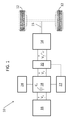
- FIG. 1 is a simplified schematic of a vehicle
- FIG. 2 is a circuit diagram of a fuel cell stack connector coupled to a power converter
- FIG. 3 is a detailed circuit diagram of a power converter.
- FIG. 4 is a detailed circuit diagram of a power converter according to another embodiment.
- fully electric vehicles can include a fuel cell and batteries, both of which provide power to an electric motor.
- contactors open and electrically disconnect the fuel cell from the rest of the vehicle.
- the contactor could become stuck in a closed position and fail to open.
- a solenoid that causes the contactor to open could fail or the contactor, due to arcing, could become welded closed.
- the contactor could become stuck open.
- some electric vehicles may require that the contactors be operating correctly before the fuel cell is activated and the electric vehicle may be started. This can help ensure that when the vehicle is turned off, the fuel cell can again be disconnected from the rest of the vehicle.
- Such vehicles may include a testing circuit/logic that performs a self-test to determine whether the contactors have become stuck or are otherwise operating incorrectly. In order to properly perform such tests, in one embodiment, power is back fed from a power converter to the contactors. This is in contrast to operation of current electric vehicles where power only flows from the fuel cell to the power converter.
- FIG. 1 is a simplified schematic of a vehicle 10 .
- the vehicle 10 is a fully electric vehicle but could include an ICE in another embodiment.
- the illustrated vehicle 10 includes wheels 12 that are driven by an electric motor 14 .
- the wheels 12 are coupled to the electric motor 14 via a transmission system illustrated by reference numeral 15 .
- the electric motor 14 is an alternating current (AC) motor in one embodiment. It shall be understood that the electric motor 14 could be any suitable type of electric motor as is now known or later developed. In the following discussion the electric motor 14 will be assumed to be an AC motor.
- AC alternating current
- the illustrated vehicle 10 includes a fuel cell 16 and high voltage (HV) batteries 22 .
- the fuel cell 16 is the primary source of electric power provided to the electric motor 14 .
- the operation of a fuel cell is generally known and generally includes harnessing energy from electrochemical reactions between hydrogen and oxygen.
- V 1 a voltage
- V 2 a higher voltage
- V 1 and V 2 are DC voltages in one embodiment.
- the power converter 18 is illustrated as a power converter. It shall be understood, however, that the power converter could be implemented as a buck converter or other suitable converter.
- the power converter 18 may include a controller (not shown) that receives power from an isolated power source (represented in FIG. 3 as 82 ) to drive a switch (e.g. an insulated gate bipolar transistor (IGBT)) used in converting V 1 to V 2 .
- the vehicle illustrated in FIG. 1 also includes a power source 24 coupled to power converter 18 .
- the power source 24 is a standard 12V car battery included in a conventional ICE and, as explained below, is isolated from one or both the fuel cell 16 and the HV batteries 22 .
- the power source 24 can serve several functions in the vehicle 10 but for purposes herein it shall be assumed that it functions as least to provide power for the components that drive the switch in the power converter 18 .
- the vehicle 10 also includes an inverter 20 that forms a uni- or polyphase AC output (V 3 ) from V 2 .
- V 3 is provided to electric motor 14 .
- the fuel cell 16 may not provide power rapidly enough to cause the desired acceleration.
- the vehicle 10 also includes one or more high voltage batteries (collectively referred to by reference numeral 22 ) coupled to the power converter 18 .
- the batteries 22 may also, as is known in the art, provide a repository for power produced during braking (regenerative braking) of the electric motor 14 .
- power only flowed from the fuel cell 16 to the power converter 18 and not in the other direction.
- power is back fed from the power converter 18 to the fuel cell 16 to be used during one or more contactor diagnostic tests.
- an input capacitor C 1 of the power converter 18 is charged and provides a source of power used in contactor diagnostic tests.
- FIG. 2 is a circuit diagram illustrating portions of both the fuel cell 16 and the power converter 18 . It shall be understood that both the fuel cell 16 and the power converter 18 can include more components than shown in FIG. 2 .
- the portion of the fuel cell 16 illustrated in FIG. 2 is commonly referred to as the stack interface unit and is generally denoted by reference numeral 50 .
- the stack interface 50 is used to electrically couple or otherwise connect the fuel cell stack (not shown) to external elements.
- the fuel cell stack is, in one embodiment, a collection of individual fuel cells connected in series to increase output voltage.
- the stack interface unit 50 includes one or more contactors 52 .
- the contactors 52 can be any kind of switch that allows for the opening and closing of the circuit.
- one or more of the contactors 52 are mechanical switches that both physically and electrically decouple two electrical components. In operation, the contactors 52 serve to electrically connect or disconnect the fuel cell 16 from at least the power converter 18 and, in one example, from any other portions of the vehicle 10 ( FIG. 1 ).
- the stack interface unit 50 also includes a contactor test unit 54 coupled in parallel with the output (illustrated as V out ) of the fuel cell 16 .
- the contactor test unit 54 includes logic 55 that causes the contactors 52 a and 52 b to be individually opened and closed in a particular pattern. A voltage applied at node 58 will cause currents to flow or voltages to arise based on the configuration of the contactors 52 .
- the test unit 54 can also include sensors 56 to measure these currents and voltages. Based on the measured voltages and currents, the test unit 54 can determine if the contactors 52 are working properly. The particular details of how the test is performed can vary and is within the knowledge of the skilled artisan based on the teachings herein.
- the power converter 18 illustrated in FIG. 2 includes the conventional components of a boost converter, namely, inductor L 1 , switch S 1 (illustrated as an IGBT and including diode D 2 disposed across the collector/emitter of the IGBT) and diode D 1 coupled to on positive and negative input lines 62 , 64 .
- the difference in voltage between positive and negative input lines 62 , 64 is equal to V 1 .
- negative input line 64 may express a negative voltage with respect to ground in one embodiment. That is, in one embodiment, negative input line 64 is not a reference (ground) voltage.
- inductor L 1 is coupled between node 58 and the anode of diode D 1 .
- Switch S 1 is connected such that its collector is coupled to the anode of diode D 1 and its emitter is coupled to negative input line 64 .
- the power converter 18 further includes a bulk capacitor C bulk coupled between the cathode of diode D 1 and the negative input line 64 that serves to smooth output ripples in V 2 . While not illustrated in FIG. 2 it shall be understood that a switch controller 70 ( FIG. 3 ) is coupled to and drives the opening and closing of the switch S 1 .
- the power converter 18 also includes input capacitor C 1 coupled across V 1 .
- C 1 serves as a filter capacitor to smooth the input voltage V 1 received by the power converter 18 .
- current/power typically only flows from the fuel cell 16 to the power converter 18 , not the reverse.
- input capacitor C 1 is charged and is used to provide a stable voltage (and a current) back into the fuel cell 16 so that the test unit 54 can effectively perform contactor diagnostics as described above. As will become apparent from the following description, such power can be provided without additional power supply elements than those currently existing in fully electric vehicles or hybrid electric vehicles.
- the power converter 18 includes a contactor diagnostic supply interface 66 coupled either directly or indirectly to the collector of the switch S 1 .
- the contactor diagnostic supply interface 66 is formed as one or serially connected diodes and resistors.
- the contactor diagnostic supply interface 66 can be formed as a charge pump.
- the contactor diagnostic supply interface 66 can be coupled, through an isolating power supply 82 ( FIG. 3 ), to the power source 24 ( FIG. 1 ) already present in the vehicle. As such, C 1 can be charged and used to provide power for testing the contactors 52 without provision of an additional power source.
- FIG. 3 is a schematic of a power converter 18 according to one embodiment.
- the power converter 18 includes an inductor L 1 , a diode D 1 , and a switch S 1 .
- the power converter 18 includes switch controller 70 .
- the switch controller receives power from an isolating power supply 82 .
- the isolating power supply 82 serves to isolate power supply 24 from one or both of the fuel cell and the HV batteries.
- the isolating power supply 82 can include a flyback DC to DC converter.
- isolating power supply 82 provides positive and negative voltages via connections 72 and 74 , respectively, to controller 70 .
- the controller 70 uses the voltages it receives to create differential voltages on its output lines 76 , 78 , 80 with output line 78 serving as a reference to control the opening and closing of switch S 1 in a manner as is known in the art.
- the bulk capacitor C bulk is charged to V 2 and fluctuations from this voltage are smoothed by high voltage batteries 22 .
- the high voltage batteries 22 are blocked from providing power to the input capacitor C 1 by diode D 1 .
- switch S 1 is opened. Current then flows from isolating power supply 82 , through contactor diagnostic supply interface 66 and causes capacitor C 1 to charge. This charge can then be used to provide a source of power that can used to perform diagnostics on the contactors 52 ( FIG. 2 ). This may be accomplished by coupling the contactor diagnostic supply interface 66 between the positive output 72 and the collector of the switch S 1 as illustrated in FIG. 3 .
- the contactor diagnostic supply interface 66 is formed of a serial connection of one or more resistors and one or more diodes.
- the contactor diagnostic supply interface 66 is formed as a charge pump. Such an embodiment may be useful if a larger voltage than can be supplied by the isolating power supply 82 is needed on the input capacitor C 1 to perform the contactor diagnostic.
- embodiments disclosed herein can effectively provide charge on input capacitor C 1 that can be used to perform contactor diagnostics. This charge is provided by using elements (power supplies) already present in a vehicle and by adding only minimal circuitry.
Landscapes
- Engineering & Computer Science (AREA)
- Life Sciences & Earth Sciences (AREA)
- Sustainable Energy (AREA)
- Power Engineering (AREA)
- Transportation (AREA)
- Mechanical Engineering (AREA)
- Sustainable Development (AREA)
- Electric Propulsion And Braking For Vehicles (AREA)
Abstract
Description
Claims (18)
Priority Applications (3)
| Application Number | Priority Date | Filing Date | Title |
|---|---|---|---|
| US13/653,003 US9434258B2 (en) | 2011-11-18 | 2012-10-16 | Power converter with diagnostic unit power supply output |
| DE102012220795.3A DE102012220795B4 (en) | 2011-11-18 | 2012-11-14 | Power converter with a power supply output for a diagnostic unit |
| CN201210558534.7A CN103121411B (en) | 2011-11-18 | 2012-11-16 | There is the power inverter that the supply of diagnosis unit power exports |
Applications Claiming Priority (2)
| Application Number | Priority Date | Filing Date | Title |
|---|---|---|---|
| US201161561466P | 2011-11-18 | 2011-11-18 | |
| US13/653,003 US9434258B2 (en) | 2011-11-18 | 2012-10-16 | Power converter with diagnostic unit power supply output |
Publications (2)
| Publication Number | Publication Date |
|---|---|
| US20130127243A1 US20130127243A1 (en) | 2013-05-23 |
| US9434258B2 true US9434258B2 (en) | 2016-09-06 |
Family
ID=48426083
Family Applications (1)
| Application Number | Title | Priority Date | Filing Date |
|---|---|---|---|
| US13/653,003 Expired - Fee Related US9434258B2 (en) | 2011-11-18 | 2012-10-16 | Power converter with diagnostic unit power supply output |
Country Status (2)
| Country | Link |
|---|---|
| US (1) | US9434258B2 (en) |
| CN (1) | CN103121411B (en) |
Cited By (1)
| Publication number | Priority date | Publication date | Assignee | Title |
|---|---|---|---|---|
| US20220166232A1 (en) * | 2019-08-13 | 2022-05-26 | Autel Robotics Co,. Ltd. | Charging management system and method, device, and storage medium |
Families Citing this family (5)
| Publication number | Priority date | Publication date | Assignee | Title |
|---|---|---|---|---|
| JP5286456B1 (en) * | 2011-12-09 | 2013-09-11 | 本田技研工業株式会社 | Power control device |
| US10090125B2 (en) * | 2016-04-27 | 2018-10-02 | GM Global Technology Operations LLC | Methods of determining the order of operating contactors in high voltage circuits |
| DE102016122002A1 (en) * | 2016-11-16 | 2018-05-17 | Dr. Ing. H.C. F. Porsche Aktiengesellschaft | Vehicle, in particular an electric vehicle or a hybrid vehicle and method for charging an energy storage cell of a vehicle |
| JP6828559B2 (en) * | 2017-03-31 | 2021-02-10 | トヨタ自動車株式会社 | Fuel cell system, fuel cell system control method and vehicle equipped with fuel cell system |
| US20230318445A1 (en) * | 2022-04-01 | 2023-10-05 | Ford Global Technologies, Llc | Automotive dc-dc power converter with flyback converter for input capacitor charging |
Citations (33)
| Publication number | Priority date | Publication date | Assignee | Title |
|---|---|---|---|---|
| US4241250A (en) * | 1979-06-25 | 1980-12-23 | General Electric Company | Induction cooking system |
| US4803472A (en) | 1985-12-10 | 1989-02-07 | Sgs Microelecttronica S.P.A. | Phase signal detecting device |
| US5373195A (en) | 1992-12-23 | 1994-12-13 | General Electric Company | Technique for decoupling the energy storage system voltage from the DC link voltage in AC electric drive systems |
| US5666029A (en) * | 1994-05-03 | 1997-09-09 | The Bodine Company | Fluorescent emergency ballast self test circuit |
| US5796175A (en) | 1995-08-03 | 1998-08-18 | Honda Giken Kogyo Kabushiki Kaisha | Power supply control device for electric vehicle |
| US5991182A (en) | 1995-12-29 | 1999-11-23 | Em Microelectric -Marin Sa | Active rectifier having minimal energy losses |
| US6239582B1 (en) | 1999-11-04 | 2001-05-29 | Satcon Technology Corporation | Motor vehicle alternator having a single voltage sensor and a half-wave controlled rectifier bridge for increasing output |
| US6271712B1 (en) | 1999-04-07 | 2001-08-07 | Semiconductor Components Industries Llc | Synchronous rectifier and method of operation |
| US6275093B1 (en) | 1998-02-25 | 2001-08-14 | Intersil Corporation | IGBT gate drive circuit with short circuit protection |
| US20040053082A1 (en) * | 2002-09-13 | 2004-03-18 | Mccluskey Donald | Method and system for balanced control of backup power |
| US6747880B2 (en) | 2001-03-28 | 2004-06-08 | Koninklijke Philips Electronics N.V. | Self-powered synchronous rectifiers |
| US6978854B1 (en) | 2004-07-28 | 2005-12-27 | Ford Global Technologies, Llc | Hybrid electric vehicle powertrain with an alternate operating mode without a high voltage system |
| US7015561B2 (en) | 2000-02-08 | 2006-03-21 | Vlt, Inc. | Active rectifier |
| US7084609B2 (en) | 2004-01-29 | 2006-08-01 | Visteon Global Technologies, Inc. | Alternator controlled rectifier |
| US7116080B2 (en) | 2004-07-07 | 2006-10-03 | Visteon Global Technologies, Inc. | Alternator rectifier with coil-sensor controlled MOSFETs |
| US7199636B2 (en) | 2004-03-31 | 2007-04-03 | Matsushita Electric Industrial Co., Ltd. | Active diode |
| US7271570B2 (en) | 2005-12-21 | 2007-09-18 | Temic Automotive Of North America, Inc. | Active rectification of alternator output without using a position sensor |
| US7292445B2 (en) | 2003-02-25 | 2007-11-06 | Siliconix Technology C.V.-Ir | Active integrated rectifier regulator |
| US7436080B2 (en) | 2003-02-10 | 2008-10-14 | Siemens Aktiengesellschaft | Device for supplying power to a two-voltage vehicle electrical system equipped with safety-relevant components |
| US20080284385A1 (en) | 2007-05-17 | 2008-11-20 | Gm Global Technology Operations, Inc. | High efficiency generator |
| CN101540560A (en) | 2008-03-17 | 2009-09-23 | 李鑫 | DC/AC converter system for fuel battery |
| US20100060245A1 (en) | 2008-09-08 | 2010-03-11 | Gm Global Technology Operations, Inc. | Rectifying circuit for a multiphase electric machine |
| US20100225258A1 (en) | 2009-03-09 | 2010-09-09 | Gm Global Technology Operations, Inc. | Control of an alternator-starter for a hybrid electric vehicle having a disconnected high-voltage battery |
| US20100236851A1 (en) | 2009-03-19 | 2010-09-23 | Gm Global Technology Operations, Inc. | Control of a starter-alternator during a high-voltage battery fault condition |
| US20100250194A1 (en) * | 2009-03-27 | 2010-09-30 | Gm Global Technology Operations, Inc. | Electrical system integrity testing methods and apparatus |
| US20110050174A1 (en) | 2009-08-31 | 2011-03-03 | Robert Dean King | Apparatus for transferring energy using onboard power electronics and method of manufacturing same |
| US20110101774A1 (en) | 2008-04-14 | 2011-05-05 | Arndt Wagner | Emergency energy supply device for a hybrid vehicle |
| US7961449B2 (en) | 2008-03-17 | 2011-06-14 | Robert Bosch Gmbh | Extended controller keep alive system and method |
| US20110144842A1 (en) | 2009-12-10 | 2011-06-16 | Delta Electronics, Inc. | Dc-to-dc converting apparatus with communication function for vehicle |
| US8140205B2 (en) | 2006-01-13 | 2012-03-20 | Nissan Motor Co., Ltd. | Driving system for hybrid vehicle |
| US8170744B2 (en) * | 2003-04-09 | 2012-05-01 | Yazaki Corporation | Front electronic equipment system with a LIN-subbus |
| US8606447B2 (en) | 2011-05-23 | 2013-12-10 | GM Global Technology Operations LLC | Method and apparatus to operate a powertrain system including an electric machine having a disconnected high-voltage battery |
| US8779706B2 (en) * | 2010-09-17 | 2014-07-15 | Denso Corporation | Control apparatus for rotary electric machines |
Family Cites Families (6)
| Publication number | Priority date | Publication date | Assignee | Title |
|---|---|---|---|---|
| US7715217B2 (en) * | 2005-03-31 | 2010-05-11 | Toyota Jidosha Kabushiki Kaisha | Voltage conversion device and vehicle |
| US7615887B2 (en) * | 2007-03-09 | 2009-11-10 | Gm Global Technology Operations, Inc. | Method and system for operating a power converter |
| JP4905715B2 (en) * | 2007-09-14 | 2012-03-28 | 株式会社東芝 | Electric vehicle power supply |
| CN101291005B (en) * | 2008-04-30 | 2010-11-24 | 刘云海 | Energy management system of externally charging typed hybrid power vehicle |
| CN201285778Y (en) * | 2008-10-31 | 2009-08-05 | 华南理工大学 | Power converting control apparatus for fuel cell |
| CN101905695A (en) * | 2010-08-05 | 2010-12-08 | 张育华 | Hybrid vehicle energy management method |
-
2012
- 2012-10-16 US US13/653,003 patent/US9434258B2/en not_active Expired - Fee Related
- 2012-11-16 CN CN201210558534.7A patent/CN103121411B/en not_active Expired - Fee Related
Patent Citations (37)
| Publication number | Priority date | Publication date | Assignee | Title |
|---|---|---|---|---|
| US4241250A (en) * | 1979-06-25 | 1980-12-23 | General Electric Company | Induction cooking system |
| US4803472A (en) | 1985-12-10 | 1989-02-07 | Sgs Microelecttronica S.P.A. | Phase signal detecting device |
| US5373195A (en) | 1992-12-23 | 1994-12-13 | General Electric Company | Technique for decoupling the energy storage system voltage from the DC link voltage in AC electric drive systems |
| US5666029A (en) * | 1994-05-03 | 1997-09-09 | The Bodine Company | Fluorescent emergency ballast self test circuit |
| US5796175A (en) | 1995-08-03 | 1998-08-18 | Honda Giken Kogyo Kabushiki Kaisha | Power supply control device for electric vehicle |
| US5991182A (en) | 1995-12-29 | 1999-11-23 | Em Microelectric -Marin Sa | Active rectifier having minimal energy losses |
| US6275093B1 (en) | 1998-02-25 | 2001-08-14 | Intersil Corporation | IGBT gate drive circuit with short circuit protection |
| US6271712B1 (en) | 1999-04-07 | 2001-08-07 | Semiconductor Components Industries Llc | Synchronous rectifier and method of operation |
| US6239582B1 (en) | 1999-11-04 | 2001-05-29 | Satcon Technology Corporation | Motor vehicle alternator having a single voltage sensor and a half-wave controlled rectifier bridge for increasing output |
| US7015561B2 (en) | 2000-02-08 | 2006-03-21 | Vlt, Inc. | Active rectifier |
| US6747880B2 (en) | 2001-03-28 | 2004-06-08 | Koninklijke Philips Electronics N.V. | Self-powered synchronous rectifiers |
| US20040053082A1 (en) * | 2002-09-13 | 2004-03-18 | Mccluskey Donald | Method and system for balanced control of backup power |
| US7436080B2 (en) | 2003-02-10 | 2008-10-14 | Siemens Aktiengesellschaft | Device for supplying power to a two-voltage vehicle electrical system equipped with safety-relevant components |
| US7292445B2 (en) | 2003-02-25 | 2007-11-06 | Siliconix Technology C.V.-Ir | Active integrated rectifier regulator |
| US8170744B2 (en) * | 2003-04-09 | 2012-05-01 | Yazaki Corporation | Front electronic equipment system with a LIN-subbus |
| US7084609B2 (en) | 2004-01-29 | 2006-08-01 | Visteon Global Technologies, Inc. | Alternator controlled rectifier |
| US7199636B2 (en) | 2004-03-31 | 2007-04-03 | Matsushita Electric Industrial Co., Ltd. | Active diode |
| US7227340B2 (en) | 2004-07-07 | 2007-06-05 | Ford Motor Company | Alternator rectifier with coil-sensor controlled MOSFETs |
| US7116080B2 (en) | 2004-07-07 | 2006-10-03 | Visteon Global Technologies, Inc. | Alternator rectifier with coil-sensor controlled MOSFETs |
| US6978854B1 (en) | 2004-07-28 | 2005-12-27 | Ford Global Technologies, Llc | Hybrid electric vehicle powertrain with an alternate operating mode without a high voltage system |
| US7271570B2 (en) | 2005-12-21 | 2007-09-18 | Temic Automotive Of North America, Inc. | Active rectification of alternator output without using a position sensor |
| US8140205B2 (en) | 2006-01-13 | 2012-03-20 | Nissan Motor Co., Ltd. | Driving system for hybrid vehicle |
| US20080284385A1 (en) | 2007-05-17 | 2008-11-20 | Gm Global Technology Operations, Inc. | High efficiency generator |
| US7961449B2 (en) | 2008-03-17 | 2011-06-14 | Robert Bosch Gmbh | Extended controller keep alive system and method |
| CN101540560A (en) | 2008-03-17 | 2009-09-23 | 李鑫 | DC/AC converter system for fuel battery |
| US20110101774A1 (en) | 2008-04-14 | 2011-05-05 | Arndt Wagner | Emergency energy supply device for a hybrid vehicle |
| US20100060245A1 (en) | 2008-09-08 | 2010-03-11 | Gm Global Technology Operations, Inc. | Rectifying circuit for a multiphase electric machine |
| US8064227B2 (en) | 2008-09-08 | 2011-11-22 | GM Global Technology Operations LLC | Rectifying circuit for a multiphase electric machine |
| US20100225258A1 (en) | 2009-03-09 | 2010-09-09 | Gm Global Technology Operations, Inc. | Control of an alternator-starter for a hybrid electric vehicle having a disconnected high-voltage battery |
| US8314578B2 (en) | 2009-03-09 | 2012-11-20 | GM Global Technology Operations LLC | Control of an alternator-starter for a hybrid electric vehicle having a disconnected high-voltage battery |
| US20100236851A1 (en) | 2009-03-19 | 2010-09-23 | Gm Global Technology Operations, Inc. | Control of a starter-alternator during a high-voltage battery fault condition |
| US8020650B2 (en) | 2009-03-19 | 2011-09-20 | GM Global Technology Operations LLC | Control of a starter-alternator during a high-voltage battery fault condition |
| US20100250194A1 (en) * | 2009-03-27 | 2010-09-30 | Gm Global Technology Operations, Inc. | Electrical system integrity testing methods and apparatus |
| US20110050174A1 (en) | 2009-08-31 | 2011-03-03 | Robert Dean King | Apparatus for transferring energy using onboard power electronics and method of manufacturing same |
| US20110144842A1 (en) | 2009-12-10 | 2011-06-16 | Delta Electronics, Inc. | Dc-to-dc converting apparatus with communication function for vehicle |
| US8779706B2 (en) * | 2010-09-17 | 2014-07-15 | Denso Corporation | Control apparatus for rotary electric machines |
| US8606447B2 (en) | 2011-05-23 | 2013-12-10 | GM Global Technology Operations LLC | Method and apparatus to operate a powertrain system including an electric machine having a disconnected high-voltage battery |
Non-Patent Citations (2)
| Title |
|---|
| Chinese Office Action for Chinese Patent Application for Invention No. 201210558534.7, Mailed on Aug. 5, 2014, 7 pages. |
| Finco, S., et al. "High Performance NMOS Active Zener and Rectifier Diodes". IEEE 2001. pp. 658-663. |
Cited By (1)
| Publication number | Priority date | Publication date | Assignee | Title |
|---|---|---|---|---|
| US20220166232A1 (en) * | 2019-08-13 | 2022-05-26 | Autel Robotics Co,. Ltd. | Charging management system and method, device, and storage medium |
Also Published As
| Publication number | Publication date |
|---|---|
| CN103121411A (en) | 2013-05-29 |
| US20130127243A1 (en) | 2013-05-23 |
| CN103121411B (en) | 2016-01-06 |
Similar Documents
| Publication | Publication Date | Title |
|---|---|---|
| US11070133B2 (en) | Power system | |
| US9956882B2 (en) | Electric power storage system | |
| US9873339B2 (en) | Vehicle, power source system, and control method of power source system | |
| CN106394271B (en) | High voltage battery contactor arrangement for DC fast charging | |
| US7816804B2 (en) | Power supply device and control method of the power supply device | |
| US8471413B2 (en) | Control device of power supply circuit | |
| US10654376B2 (en) | Fuel Cell System | |
| CN103770657B (en) | The control method of vehicle, power-supply system and power-supply system | |
| CN105246734B (en) | Operate the method and arrangement of hybrid vehicle | |
| US9434258B2 (en) | Power converter with diagnostic unit power supply output | |
| US10449953B2 (en) | Apparatus and method for controlling power generation in a vehicle | |
| US20100244558A1 (en) | Power supply apparatus for vehicle | |
| CN108232251B (en) | Drive system and vehicle | |
| JP2013038895A (en) | Discharge circuit for capacitor | |
| CN105904978A (en) | Range extension type electric vehicle with double power battery packs | |
| JP5949436B2 (en) | Vehicle, power supply system, and control method for power supply system | |
| US10099680B2 (en) | Hybrid vehicle | |
| CN107487223B (en) | Vehicle system for evaluating a voltage converter | |
| US10158246B2 (en) | Energy storage device, transport apparatus, and control method | |
| US11702060B2 (en) | Power relay assembly and vehicle comprising the same and control method of power relay assembly | |
| US20230365013A1 (en) | Power supply system and relay state determining method | |
| KR102954468B1 (en) | Power relay assembly, vehicle comprising thereof and controlling method of power relay assembly | |
| EP4375113A1 (en) | A method for operating a switching arrangement | |
| CN112740499A (en) | Control method of electric vehicle and electric vehicle system | |
| KR20100113248A (en) | Cooling system of a high voltage battery of a car |
Legal Events
| Date | Code | Title | Description |
|---|---|---|---|
| AS | Assignment |
Owner name: GM GLOBAL TECHNOLOGY OPERATIONS LLC, MICHIGAN Free format text: ASSIGNMENT OF ASSIGNORS INTEREST;ASSIGNORS:BERG, JOSEPH;MEYER, JOHN W., III;HAMILTON, WESLEY O.;AND OTHERS;REEL/FRAME:029138/0512 Effective date: 20121015 |
|
| AS | Assignment |
Owner name: WILMINGTON TRUST COMPANY, DELAWARE Free format text: SECURITY AGREEMENT;ASSIGNOR:GM GLOBAL TECHNOLOGY OPERATIONS LLC;REEL/FRAME:030694/0591 Effective date: 20101027 |
|
| AS | Assignment |
Owner name: GM GLOBAL TECHNOLOGY OPERATIONS LLC, MICHIGAN Free format text: RELEASE BY SECURED PARTY;ASSIGNOR:WILMINGTON TRUST COMPANY;REEL/FRAME:034287/0601 Effective date: 20141017 |
|
| FEPP | Fee payment procedure |
Free format text: PAYOR NUMBER ASSIGNED (ORIGINAL EVENT CODE: ASPN); ENTITY STATUS OF PATENT OWNER: LARGE ENTITY |
|
| ZAAA | Notice of allowance and fees due |
Free format text: ORIGINAL CODE: NOA |
|
| ZAAB | Notice of allowance mailed |
Free format text: ORIGINAL CODE: MN/=. |
|
| STCF | Information on status: patent grant |
Free format text: PATENTED CASE |
|
| MAFP | Maintenance fee payment |
Free format text: PAYMENT OF MAINTENANCE FEE, 4TH YEAR, LARGE ENTITY (ORIGINAL EVENT CODE: M1551); ENTITY STATUS OF PATENT OWNER: LARGE ENTITY Year of fee payment: 4 |
|
| FEPP | Fee payment procedure |
Free format text: MAINTENANCE FEE REMINDER MAILED (ORIGINAL EVENT CODE: REM.); ENTITY STATUS OF PATENT OWNER: LARGE ENTITY |
|
| LAPS | Lapse for failure to pay maintenance fees |
Free format text: PATENT EXPIRED FOR FAILURE TO PAY MAINTENANCE FEES (ORIGINAL EVENT CODE: EXP.); ENTITY STATUS OF PATENT OWNER: LARGE ENTITY |
|
| STCH | Information on status: patent discontinuation |
Free format text: PATENT EXPIRED DUE TO NONPAYMENT OF MAINTENANCE FEES UNDER 37 CFR 1.362 |
|
| FP | Lapsed due to failure to pay maintenance fee |
Effective date: 20240906 |