US9433846B2 - Golf training apparatus - Google Patents

Golf training apparatus Download PDF

Info

Publication number
US9433846B2
US9433846B2 US14/827,260 US201514827260A US9433846B2 US 9433846 B2 US9433846 B2 US 9433846B2 US 201514827260 A US201514827260 A US 201514827260A US 9433846 B2 US9433846 B2 US 9433846B2
Authority
US
United States
Prior art keywords
resistance
sled
training apparatus
rail
golf training
Prior art date
Legal status (The legal status is an assumption and is not a legal conclusion. Google has not performed a legal analysis and makes no representation as to the accuracy of the status listed.)
Active
Application number
US14/827,260
Other versions
US20160045804A1 (en
Inventor
Charles E. Lynch
Eric R. Fox
Current Assignee (The listed assignees may be inaccurate. Google has not performed a legal analysis and makes no representation or warranty as to the accuracy of the list.)
Individual
Original Assignee
Individual
Priority date (The priority date is an assumption and is not a legal conclusion. Google has not performed a legal analysis and makes no representation as to the accuracy of the date listed.)
Filing date
Publication date
Application filed by Individual filed Critical Individual
Priority to US14/827,260 priority Critical patent/US9433846B2/en
Publication of US20160045804A1 publication Critical patent/US20160045804A1/en
Application granted granted Critical
Publication of US9433846B2 publication Critical patent/US9433846B2/en
Active legal-status Critical Current
Anticipated expiration legal-status Critical

Links

Images

Classifications

    • AHUMAN NECESSITIES
    • A63SPORTS; GAMES; AMUSEMENTS
    • A63BAPPARATUS FOR PHYSICAL TRAINING, GYMNASTICS, SWIMMING, CLIMBING, OR FENCING; BALL GAMES; TRAINING EQUIPMENT
    • A63B69/00Training appliances or apparatus for special sports
    • A63B69/36Training appliances or apparatus for special sports for golf
    • A63B69/3621Contacting or non-contacting mechanical means for guiding the swing
    • AHUMAN NECESSITIES
    • A63SPORTS; GAMES; AMUSEMENTS
    • A63BAPPARATUS FOR PHYSICAL TRAINING, GYMNASTICS, SWIMMING, CLIMBING, OR FENCING; BALL GAMES; TRAINING EQUIPMENT
    • A63B71/00Games or sports accessories not covered in groups A63B1/00 - A63B69/00
    • A63B71/06Indicating or scoring devices for games or players, or for other sports activities
    • A63B71/0619Displays, user interfaces and indicating devices, specially adapted for sport equipment, e.g. display mounted on treadmills
    • A63B2071/0655Tactile feedback
    • AHUMAN NECESSITIES
    • A63SPORTS; GAMES; AMUSEMENTS
    • A63BAPPARATUS FOR PHYSICAL TRAINING, GYMNASTICS, SWIMMING, CLIMBING, OR FENCING; BALL GAMES; TRAINING EQUIPMENT
    • A63B71/00Games or sports accessories not covered in groups A63B1/00 - A63B69/00
    • A63B71/06Indicating or scoring devices for games or players, or for other sports activities
    • A63B2071/0694Visual indication, e.g. Indicia
    • AHUMAN NECESSITIES
    • A63SPORTS; GAMES; AMUSEMENTS
    • A63BAPPARATUS FOR PHYSICAL TRAINING, GYMNASTICS, SWIMMING, CLIMBING, OR FENCING; BALL GAMES; TRAINING EQUIPMENT
    • A63B2208/00Characteristics or parameters related to the user or player
    • A63B2208/02Characteristics or parameters related to the user or player posture
    • A63B2208/0204Standing on the feet
    • AHUMAN NECESSITIES
    • A63SPORTS; GAMES; AMUSEMENTS
    • A63BAPPARATUS FOR PHYSICAL TRAINING, GYMNASTICS, SWIMMING, CLIMBING, OR FENCING; BALL GAMES; TRAINING EQUIPMENT
    • A63B2210/00Space saving
    • A63B2210/50Size reducing arrangements for stowing or transport
    • A63B69/3641
    • AHUMAN NECESSITIES
    • A63SPORTS; GAMES; AMUSEMENTS
    • A63BAPPARATUS FOR PHYSICAL TRAINING, GYMNASTICS, SWIMMING, CLIMBING, OR FENCING; BALL GAMES; TRAINING EQUIPMENT
    • A63B69/00Training appliances or apparatus for special sports
    • A63B69/36Training appliances or apparatus for special sports for golf
    • A63B69/3676Training appliances or apparatus for special sports for golf for putting
    • AHUMAN NECESSITIES
    • A63SPORTS; GAMES; AMUSEMENTS
    • A63BAPPARATUS FOR PHYSICAL TRAINING, GYMNASTICS, SWIMMING, CLIMBING, OR FENCING; BALL GAMES; TRAINING EQUIPMENT
    • A63B71/00Games or sports accessories not covered in groups A63B1/00 - A63B69/00
    • A63B71/04Games or sports accessories not covered in groups A63B1/00 - A63B69/00 for small-room or indoor sporting games

Definitions

  • the present invention relates generally to sports training devices and more particularly to a golf training apparatus that helps a golfer feel and understand the movement through impact and thus improve their swing.
  • the present invention is a device that helps a golfer improve their swing by providing a track over which to swing the club, a strike plate which swivels to keep contact with the club as long as possible and a resistance to movement over the strike plate in the track so the player understands the weight transfer required in a golf swing.
  • An embodiment includes a sled sliding one or more rails with a front and rear strike plate and a resistance mechanism that provides adjustable resistance to the swing using at least one pad attached to the sled to contact the rail. The user can set different ranges of resistance as training proceeds. A golfer using the invention encounters one of the strike plates on the backswing and another of the strike plates on a foreswing.
  • FIG. 1 shows a top perspective view of an embodiment of the present invention.
  • FIG. 2 shows a golfer using the present invention. The golfer is just beginning a swing.
  • FIG. 3 shows the backstroke against resistance
  • FIG. 4 shows the forestroke against resistance
  • FIG. 5 is a different perspective view of the embodiment of FIG. 1 .
  • FIG. 6 shows the components of the embodiment of FIG. 1 .
  • FIG. 7 shows different positions of the slider on the rails.
  • FIG. 8 shows details of a resistance mechanism.
  • FIG. 9 shows how the resistance mechanism is adjustable.
  • FIG. 10 shows details of the resistance pad and biasing springs.
  • FIG. 11 shows an optional resistance range adjustment.
  • FIG. 12 shows an alternate embodiment of the invention with a single rail.
  • FIG. 13 shows the resistance mechanism in the embodiment of FIG. 12 .
  • FIG. 14 shows details of the front or rear strike plate in this embodiment.
  • FIG. 15 shows details of the swivel mechanism for the strike plates in this embodiment.
  • FIG. 1 shows an embodiment of the present invention.
  • the apparatus includes a frame and a sliding sled section with two raised plates.
  • the device is secured to a base (which can be further secured to a floor), and the golfer stands next to it. He engages the first plate on the backswing and the second plate on the foreswing.
  • the plates and sliding sled section slide during the swing providing an adjustable resistance.
  • the plates swivel about a vertical axis for about 10 to 20 degrees total to help maintain maximum contact with the club.
  • FIGS. 2-4 show the start, backswing and foreswing positions of the sliding sled section and the posts.
  • the golfer moves the sled backward against resistance by contacting the rear strike plate during the backswing before the club rises above the device.
  • On the foreswing the club encounters the forward strike plate and moves forward against resistance until once again the club rises above the apparatus.
  • the golfer aligns himself or herself with the device and places the club against the rear strike plate.
  • FIG. 3 he next completes the backswing. This causes the sled and strike plates to move in a rearward direction against resistance.
  • the golfer then completes the backswing raising the club off of the apparatus and begins the foreswing as shown in FIG. 4 .
  • the club encounters the forward strike plate and moves it forward along with the rails with the sled again against resistance.
  • the golfer then completes the foreswing raising the club off of the apparatus.
  • the exercise requires accuracy, and because the movement of the strike plates is against an adjustable resistance, the strength of the swing is increased.
  • FIG. 5 shows the embodiment from a different angle.
  • FIG. 6 shows different parts of the assembly.
  • a sled 1 is attached to a rear strike plate 2 and a front strike plate 3 .
  • the strike plate assembles can swivel through a predetermined angle of from approximately 5 degrees on each side of center to approximately 10 degrees each side of center to allow maximum contact with a golf club.
  • a variable resistance center section 4 moves with the sled 1 and causes an adjustable amount of resistance.
  • the sled slides on rails 5 that are attached to the main base 6 .
  • Each end has a sled stop 7 that prevents the sled 1 from leaving the rails 5 .
  • FIG. 7 shows the base 6 , rails 5 and the sled 1 in different positions.
  • the preferred length of the rails is approximately 56 inches with approximately 40 inches of travel on either side of center. These preferred dimensions are given for example only. Numerous other dimensions are within the scope of the present invention.
  • Adjustable resistance is provided by one or more resistance pads that slide and create friction against the rails as shown in FIG. 8 .
  • the resistance pads are spring biased so that Increasing spring tension increases resistance.
  • the resistance mechanism 4 can also include a set of rollers that bias the sled to the opposite side causing the rollers to ride against the outer rails. Bottom rollers 30 can be seen in FIG. 8 . There are also side rollers 32 on the side opposite to the resistance pads 24 .
  • the rails 5 can be seen.
  • FIG. 9 shows a broken-away view of the resistance pads 24 .
  • a knob 21 or other control is used to adjust resistance by moving a bar 22 or other member against the springs 23 forcing the pads 24 more tightly against the rail.
  • FIG. 10 shows a detail of the pad assembly.
  • the pad 24 is attached to a push rod 25 by a dowel pin 26 .
  • the push rod 25 is driven by the spring 23 .
  • the resistance pad 24 can be removed and is replaceable.
  • FIG. 11 shows an optional force range selection switch 27 .
  • This sliding switch presets a bias into the springs effectively shifting the range of the knob 21 .
  • An optional indicator 28 shows the level of resistance chosen.
  • FIG. 12 shows an alternate embodiment of the present invention.
  • This embodiment only has a single rail.
  • the sled 1 slides on the single rail 5 that is secured to the base 6 .
  • the rear 2 and front 3 strike plates can be seen in FIG. 12 .
  • Each end of the rail 5 has a stop or bumper 7 that prevents the sled 1 from leaving the rail.
  • the resistance mechanism 4 can be seen on the side of the sled 1 between the strike plates.
  • FIG. 13 shows a detail of the modified resistance mechanism 4 of the embodiment of FIG. 12 .
  • the pad 24 , spring 23 and bar 22 can be seen.
  • a resistance adjustment knob 21 is also visible.
  • FIG. 14 shows details of the rear 2 or front 3 strike plates in the embodiment of FIG. 12 .
  • the plates are attached to a clamp 40 by a pin 42 that passes through a flange 44 .
  • the plate engages two springs 43 on the front of the clamp 40 .
  • the front of the clamp 40 slants away in two directions allowing the plate 2 , 3 to swivel around the pin 42 through the predetermined angle.
  • FIG. 15 shows a detail of the clamp 40 in this embodiment.
  • a knob 41 with a screw holds the clamp 40 to a base 44 which can be screwed to the sled.
  • the faces of the clamp 40 slant at an angle and each receives a spring 43 . This allows the plate 2 , 3 to swivel about the pin 42 .
  • the present invention provides an economical golf training tool that simultaneously increases swing length, swing coil, swing accuracy, and increases swing strength.

Landscapes

  • Health & Medical Sciences (AREA)
  • General Health & Medical Sciences (AREA)
  • Physical Education & Sports Medicine (AREA)
  • Golf Clubs (AREA)

Abstract

A device that helps a golfer improve their swing by providing a track over which to swing the club, a strike plate which swivels to keep contact with the club as long as possible and a resistance to movement over the strike plate in the track so the player understands the weight transfer required in a golf swing. An embodiment includes a sled sliding on at least one rail with front and rear strike plates and a center resistance mechanism that provides adjustable resistance to the swing using pads to contact the rails. The user can set different ranges of resistance.

Description

This application claims priority from U.S. Provisional Patent Application No. 62/037,776 filed Aug. 15, 2014. Application 62/037,776 is hereby incorporated by reference in its entirety.
BACKGROUND
1. Field of the Invention
The present invention relates generally to sports training devices and more particularly to a golf training apparatus that helps a golfer feel and understand the movement through impact and thus improve their swing.
2. Description of the Prior Art
Golfers typically need improvement in their consistency on the course. This means improving their accuracy and distance control. There are disparate devices that purport to do this by improving alignment, swinging a weighted or contrived club, or mechanically contorting the golfer into supposedly correct positions during the swing. It would be advantageous to have a device that combines alignment with proper swing mechanics of the take-away, hinging, and backswing turn, thus demonstrating proper club-ball contact in the down-swing, all the while promoting a proper weight shift that is critical to a successful golf swing.
SUMMARY OF THE INVENTION
The present invention is a device that helps a golfer improve their swing by providing a track over which to swing the club, a strike plate which swivels to keep contact with the club as long as possible and a resistance to movement over the strike plate in the track so the player understands the weight transfer required in a golf swing. An embodiment includes a sled sliding one or more rails with a front and rear strike plate and a resistance mechanism that provides adjustable resistance to the swing using at least one pad attached to the sled to contact the rail. The user can set different ranges of resistance as training proceeds. A golfer using the invention encounters one of the strike plates on the backswing and another of the strike plates on a foreswing.
DESCRIPTION OF THE FIGURES
Attention is now directed to several drawings that illustrate features of the present invention:
FIG. 1 shows a top perspective view of an embodiment of the present invention.
FIG. 2 shows a golfer using the present invention. The golfer is just beginning a swing.
FIG. 3 shows the backstroke against resistance.
FIG. 4 shows the forestroke against resistance.
FIG. 5 is a different perspective view of the embodiment of FIG. 1.
FIG. 6 shows the components of the embodiment of FIG. 1.
FIG. 7 shows different positions of the slider on the rails.
FIG. 8 shows details of a resistance mechanism.
FIG. 9 shows how the resistance mechanism is adjustable.
FIG. 10 shows details of the resistance pad and biasing springs.
FIG. 11 shows an optional resistance range adjustment.
FIG. 12 shows an alternate embodiment of the invention with a single rail.
FIG. 13 shows the resistance mechanism in the embodiment of FIG. 12.
FIG. 14 shows details of the front or rear strike plate in this embodiment.
FIG. 15 shows details of the swivel mechanism for the strike plates in this embodiment.
Several drawings and illustrations have been presented to aid in understanding the present invention. The scope of the present invention is not limited to what is shown in the figures.
DESCRIPTION OF THE PREFERRED EMBODIMENTS
FIG. 1 shows an embodiment of the present invention. The apparatus includes a frame and a sliding sled section with two raised plates. The device is secured to a base (which can be further secured to a floor), and the golfer stands next to it. He engages the first plate on the backswing and the second plate on the foreswing. The plates and sliding sled section slide during the swing providing an adjustable resistance. The plates swivel about a vertical axis for about 10 to 20 degrees total to help maintain maximum contact with the club.
FIGS. 2-4 show the start, backswing and foreswing positions of the sliding sled section and the posts. The golfer moves the sled backward against resistance by contacting the rear strike plate during the backswing before the club rises above the device. On the foreswing, the club encounters the forward strike plate and moves forward against resistance until once again the club rises above the apparatus.
In FIG. 2, the golfer aligns himself or herself with the device and places the club against the rear strike plate. In FIG. 3, he next completes the backswing. This causes the sled and strike plates to move in a rearward direction against resistance. The golfer then completes the backswing raising the club off of the apparatus and begins the foreswing as shown in FIG. 4. The club encounters the forward strike plate and moves it forward along with the rails with the sled again against resistance. The golfer then completes the foreswing raising the club off of the apparatus. The exercise requires accuracy, and because the movement of the strike plates is against an adjustable resistance, the strength of the swing is increased.
FIG. 5 shows the embodiment from a different angle.
FIG. 6 shows different parts of the assembly. A sled 1 is attached to a rear strike plate 2 and a front strike plate 3. The strike plate assembles can swivel through a predetermined angle of from approximately 5 degrees on each side of center to approximately 10 degrees each side of center to allow maximum contact with a golf club. A variable resistance center section 4 moves with the sled 1 and causes an adjustable amount of resistance. The sled slides on rails 5 that are attached to the main base 6. Each end has a sled stop 7 that prevents the sled 1 from leaving the rails 5.
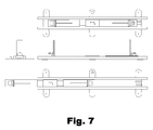
FIG. 7 shows the base 6, rails 5 and the sled 1 in different positions. The preferred length of the rails is approximately 56 inches with approximately 40 inches of travel on either side of center. These preferred dimensions are given for example only. Numerous other dimensions are within the scope of the present invention.
Adjustable resistance is provided by one or more resistance pads that slide and create friction against the rails as shown in FIG. 8. The resistance pads are spring biased so that Increasing spring tension increases resistance. The resistance mechanism 4 can also include a set of rollers that bias the sled to the opposite side causing the rollers to ride against the outer rails. Bottom rollers 30 can be seen in FIG. 8. There are also side rollers 32 on the side opposite to the resistance pads 24. The rails 5 can be seen.
FIG. 9 shows a broken-away view of the resistance pads 24. A knob 21 or other control is used to adjust resistance by moving a bar 22 or other member against the springs 23 forcing the pads 24 more tightly against the rail. There can also be an optional pad cover 31.
FIG. 10 shows a detail of the pad assembly. The pad 24 is attached to a push rod 25 by a dowel pin 26. The push rod 25 is driven by the spring 23. The resistance pad 24 can be removed and is replaceable.
FIG. 11 shows an optional force range selection switch 27. This sliding switch presets a bias into the springs effectively shifting the range of the knob 21. An optional indicator 28 shows the level of resistance chosen.
FIG. 12 shows an alternate embodiment of the present invention. This embodiment only has a single rail. The sled 1 slides on the single rail 5 that is secured to the base 6. The rear 2 and front 3 strike plates can be seen in FIG. 12. Each end of the rail 5 has a stop or bumper 7 that prevents the sled 1 from leaving the rail. The resistance mechanism 4 can be seen on the side of the sled 1 between the strike plates.
FIG. 13 shows a detail of the modified resistance mechanism 4 of the embodiment of FIG. 12. The pad 24, spring 23 and bar 22 can be seen. A resistance adjustment knob 21 is also visible.
FIG. 14 shows details of the rear 2 or front 3 strike plates in the embodiment of FIG. 12. The plates are attached to a clamp 40 by a pin 42 that passes through a flange 44. The plate engages two springs 43 on the front of the clamp 40. The front of the clamp 40 slants away in two directions allowing the plate 2,3 to swivel around the pin 42 through the predetermined angle.
FIG. 15 shows a detail of the clamp 40 in this embodiment. A knob 41 with a screw holds the clamp 40 to a base 44 which can be screwed to the sled. The faces of the clamp 40 slant at an angle and each receives a spring 43. This allows the plate 2, 3 to swivel about the pin 42.
The present invention provides an economical golf training tool that simultaneously increases swing length, swing coil, swing accuracy, and increases swing strength.
Several descriptions and illustrations have been presented to aid in understanding the present invention. One with skill in the art will realize that numerous changes and variations may be made without departing from the spirit of the invention. Each of these changes and variations is within the scope of the present invention.

Claims (19)

We claim:
1. A golf training apparatus comprising an elongated base with at least one fixed rail and a sliding sled portion that rides on the rail, the sled portion including at least one resistance pad that provides resistance against the rail as the sled portion moves, the sled portion also including a pair of separated upright strike plates that swivel through a predetermined angle about a pin, whereby a golfer can encounter one of the strike plates on a backswing and another of the strike plates on a foreswing moving the sled portion against the resistance pad.
2. The golf training apparatus of claim 1 wherein the resistance pad is configured to provide adjustable resistance.
3. The golf training apparatus of claim 1 wherein the resistance pad is replaceable.
4. The golf training apparatus of claim 1 further comprising an adjustment knob adapted to be adjusted from a first resistance to a second resistance, the second resistance being greater than the first resistance.
5. The golf training apparatus of claim 4 further comprising a switch configured to choose an absolute value of the first and second resistance.
6. The golf training apparatus of claim 4 wherein the resistance pad is raised against the rail by a spring.
7. The golf training apparatus of claim 6 wherein the spring is adjusted in bias by the adjustment knob.
8. The golf training apparatus of claim 1 wherein the rail, sled and strike plates are aluminum.
9. A golf training apparatus comprising:
at least one horizontal elongated parallel rail mounted on a base;
a sled configured to travel horizontally along said rail over the base fore and aft;
a rear strike plate attached to a first end of the sled, the rear strike plate being a flat vertical plate member perpendicular to said rail and configured to swivel through a predetermined angle about a vertical axis;
a front strike plate attached to a second end of the sled, the second strike plate also being a flat vertical plate member perpendicular to said rail and configured to swivel through the predetermined angle about the vertical axis;
a resistance member located on said sled, the resistance member having at least one pad biased by a spring to make friction contact with of said rail providing an adjustable resistance to movement of the sled according to the spring bias;
a control configured to adjust the spring bias between a first bias and a second bias, wherein the second bias is greater than the first bias.
10. The golf training apparatus of claim 9 further comprising a switch configured to offset the spring bias so the first and second bias is decreased or increased.
11. The golf training apparatus of claim 9 wherein the pad is biased by an adjustable spring.
12. The golf training apparatus of claim 9 wherein the base, rail and sled are aluminum.
13. The golf training apparatus of claim 9 wherein the pad is replaceable.
14. The golf training apparatus of claim 9 including two pads and two springs.
15. The golf training apparatus of claim 9 further comprising a horizontal member in contact with the spring, wherein the horizontal bar is adjustable with a set screw to increase or decrease the spring bias.
16. The golf training apparatus of claim 15 wherein the set screw is rotated with the knob.
17. A method of providing a golf training apparatus comprising:
providing at least one horizontal elongated rail mounted on a base;
providing a sled configured to travel horizontally along said rail over the base fore and aft;
providing a rear strike plate attached to a first end of the sled, the rear strike plate being a flat vertical plate member perpendicular to said rail;
providing a front strike plate attached to a second end of the sled, the front strike plate also being a flat vertical plate member perpendicular to said rail;
providing a resistance member located on said sled between the front and rear strike plates, the resistance member having at least one pad biased by a spring to contact said rail providing an adjustable resistance to movement of the sled according to the spring bias;
providing a control configured to adjust the spring bias between a first bias and a second bias, wherein the second bias is greater than the first bias.
18. The method of claim 17 comprising providing two pads and two springs.
19. The method of claim 17 further comprising providing a horizontal member in contact with the spring, wherein the horizontal bar is adjustable with a set screw to increase or decrease the spring bias.
US14/827,260 2014-08-15 2015-08-14 Golf training apparatus Active US9433846B2 (en)

Priority Applications (1)

Application Number Priority Date Filing Date Title
US14/827,260 US9433846B2 (en) 2014-08-15 2015-08-14 Golf training apparatus

Applications Claiming Priority (2)

Application Number Priority Date Filing Date Title
US201462037776P 2014-08-15 2014-08-15
US14/827,260 US9433846B2 (en) 2014-08-15 2015-08-14 Golf training apparatus

Publications (2)

Publication Number Publication Date
US20160045804A1 US20160045804A1 (en) 2016-02-18
US9433846B2 true US9433846B2 (en) 2016-09-06

Family

ID=55301411

Family Applications (1)

Application Number Title Priority Date Filing Date
US14/827,260 Active US9433846B2 (en) 2014-08-15 2015-08-14 Golf training apparatus

Country Status (1)

Country Link
US (1) US9433846B2 (en)

Cited By (1)

* Cited by examiner, † Cited by third party
Publication number Priority date Publication date Assignee Title
US20230226424A1 (en) * 2022-01-14 2023-07-20 Charles E. Lynch Motion Activated Golf Swing Trainer

Families Citing this family (3)

* Cited by examiner, † Cited by third party
Publication number Priority date Publication date Assignee Title
GB2588127B (en) * 2019-10-08 2022-04-06 Mcloughlin Enda Golf ball marker and alignment tool
GB2615306A (en) * 2022-01-28 2023-08-09 David Westlake Peter Golf training device
USD1097029S1 (en) * 2024-01-08 2025-10-07 Tour Aim Golf LLC Golf training aid

Citations (4)

* Cited by examiner, † Cited by third party
Publication number Priority date Publication date Assignee Title
US2084901A (en) * 1934-05-19 1937-06-22 Eisenberg William Putting device
US5301949A (en) * 1993-06-11 1994-04-12 Aupied Steven M Putt stroke training apparatus and method for using same
US5501452A (en) * 1994-06-24 1996-03-26 Halvorson; Glen A. Putting training device using muscle memory
US6699141B1 (en) * 2002-11-20 2004-03-02 Raymond J. Florian Golf putting and swing teaching aid

Patent Citations (4)

* Cited by examiner, † Cited by third party
Publication number Priority date Publication date Assignee Title
US2084901A (en) * 1934-05-19 1937-06-22 Eisenberg William Putting device
US5301949A (en) * 1993-06-11 1994-04-12 Aupied Steven M Putt stroke training apparatus and method for using same
US5501452A (en) * 1994-06-24 1996-03-26 Halvorson; Glen A. Putting training device using muscle memory
US6699141B1 (en) * 2002-11-20 2004-03-02 Raymond J. Florian Golf putting and swing teaching aid

Cited By (1)

* Cited by examiner, † Cited by third party
Publication number Priority date Publication date Assignee Title
US20230226424A1 (en) * 2022-01-14 2023-07-20 Charles E. Lynch Motion Activated Golf Swing Trainer

Also Published As

Publication number Publication date
US20160045804A1 (en) 2016-02-18

Similar Documents

Publication Publication Date Title
US5209484A (en) Golf putting improvement and teaching apparatus and method
US9433846B2 (en) Golf training apparatus
US9061190B2 (en) Baseball swing training apparatus
US20130116068A1 (en) Baseball swing line trainer
US9227124B1 (en) Apparatus and method for training a baseball pitcher
US4634131A (en) Golf putting trainer
US10814199B1 (en) Basketball shooting training device
US8956237B2 (en) Golf swing training device and method
KR20100137011A (en) Golf putting training device
WO2006062310A1 (en) Apparatus for putting correcting and training
US8915793B2 (en) Golf club swing training apparatus
US6322456B1 (en) Golf swing guide
KR102430587B1 (en) Putting practice device for making square of putter face and controlling putting power
US20130244804A1 (en) Golf Swing Training Device
US20160067585A1 (en) Sports Training Apparatus
US20180207506A1 (en) System and Method for Providing an Improved Golf Swing
US10967238B1 (en) Golf swing training apparatus and method
US8821308B2 (en) Club-swing alignment apparatus and a frame thereof
CN100398172C (en) Simple training device for volleyball players
US7717802B2 (en) Putting training device and method
KR200481306Y1 (en) Apparatus for training golf putting
US20230226424A1 (en) Motion Activated Golf Swing Trainer
JP5740579B2 (en) Golf practice equipment
CN212522944U (en) A golf putter training device
KR101381857B1 (en) Golf swing training device

Legal Events

Date Code Title Description
STCF Information on status: patent grant

Free format text: PATENTED CASE

MAFP Maintenance fee payment

Free format text: PAYMENT OF MAINTENANCE FEE, 4TH YR, SMALL ENTITY (ORIGINAL EVENT CODE: M2551); ENTITY STATUS OF PATENT OWNER: SMALL ENTITY

Year of fee payment: 4

FEPP Fee payment procedure

Free format text: 7.5 YR SURCHARGE - LATE PMT W/IN 6 MO, SMALL ENTITY (ORIGINAL EVENT CODE: M2555); ENTITY STATUS OF PATENT OWNER: SMALL ENTITY

MAFP Maintenance fee payment

Free format text: PAYMENT OF MAINTENANCE FEE, 8TH YR, SMALL ENTITY (ORIGINAL EVENT CODE: M2552); ENTITY STATUS OF PATENT OWNER: SMALL ENTITY

Year of fee payment: 8