US942554A - Last. - Google Patents
Last. Download PDFInfo
- Publication number
- US942554A US942554A US17815403A US1903178154A US942554A US 942554 A US942554 A US 942554A US 17815403 A US17815403 A US 17815403A US 1903178154 A US1903178154 A US 1903178154A US 942554 A US942554 A US 942554A
- Authority
- US
- United States
- Prior art keywords
- last
- heel
- plate
- locking
- shoulder
- Prior art date
- Legal status (The legal status is an assumption and is not a legal conclusion. Google has not performed a legal analysis and makes no representation as to the accuracy of the status listed.)
- Expired - Lifetime
Links
- 238000004904 shortening Methods 0.000 description 8
- 238000010276 construction Methods 0.000 description 4
- 230000004048 modification Effects 0.000 description 2
- 238000012986 modification Methods 0.000 description 2
- 230000000694 effects Effects 0.000 description 1
- 239000000945 filler Substances 0.000 description 1
- 238000003780 insertion Methods 0.000 description 1
- 230000037431 insertion Effects 0.000 description 1
- 238000000034 method Methods 0.000 description 1
- 230000000979 retarding effect Effects 0.000 description 1
Images
Classifications
-
- A—HUMAN NECESSITIES
- A43—FOOTWEAR
- A43D—MACHINES, TOOLS, EQUIPMENT OR METHODS FOR MANUFACTURING OR REPAIRING FOOTWEAR
- A43D3/00—Lasts
- A43D3/02—Lasts for making or repairing shoes
- A43D3/024—Lasts with a fore part and heel section relatively slideable to one another along an inclined line of cut
Definitions
- This invention relates to divided lasts and it consists in certain novel features of construction and arrangement of a last and the locking devices thereof whereby the sections of the last are locked together, which I shall now proceed to describe and claim.
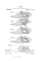
- Figure 1 represents a longitudinal section of a last containing one embodiment of my invention.
- Fig. 2 represents a similar view with the last contracted longitudinally.
- Fig. 3 represents a longitudinal section showing a modification.
- Fig. t represents a longitudinal sect-ion showing a second modification.
- Fig. 5 represents a horizontal section of the latter.
- My invention resides in providing the last with an automatically locking union and also with a yielding locking device or frictional retarding member for preventing accidental collapsing of the last.
- the last 1 comprises a fore part or section 2 and a heel part or section 3, the two sections having opposed sliding faces 4 5 slanted so that by moving the heel section 3 up along the fore section 2 from the position represented in Fi. 1 to that represented in Fig. 2, the
- last izvill be contracted longitudinally to permit it to be inserted in or withdrawn from the shoe.
- the union which permits the last to collapse or lengthen for removal from or insertion into a shoe, and which according to my invention comprises a combined lock-and-union, the form thereof herein shown consisting of a latch-plate or lever 9 pivoted on a pin 10 and arranged to project into the recess 7 of the fore section.
- a combined lock-and-union the form thereof herein shown consisting of a latch-plate or lever 9 pivoted on a pin 10 and arranged to project into the recess 7 of the fore section.
- a slot 11 occupied by a pin 12 on the fore section, said slot having a pin-guiding portion 13 and a pinlocking portion 14, the latter being located at an angle to the portion 13 and curved on an arc centered at 10.
- the latch-plate is formed with a toe 15 projecting into the spindle socket 6.
- ⁇ A spring 16 in the lower part of said socket engaging the under side of this toe, normally presses the latch-plate in a direction which tends to establish the pin 12 in the locking portion 14e of the slot 11 behind the locking shoulder 17 and to position the guiding portion 13 of said slot at an angle to the sliding faces 4 5 of the sections, as indicated in Fig. 1.
- a stop-pin 18 on the heel section 3 engages the upper edge of the latch-plate and limits the rotation of said plate in a locking direct-ion under the influence of spring 16.
- notch 19 is an open slot or notch occupied by a pin 20 on the fore section 2 and also curved on an arc centered at 10.
- the notch 19 and the locking portion 141 of slot 11 are located on opposite sides of a straight line passing through the pivot 10 and normal or perpendicular to the sliding faces 4t 5.
- This has the effect of making the inner side of portion 14, that is, the shoulder 1T, act in conjunction with the pin 12 to obstruct the upward or last-shortening movement of the heel-section 3, and of making the outer side of notch 19, that is the shoulder 21, perform a similar locking action in conjunction with the pin 20. herefore when the parts have the lasteXtended position represented in Fig.
- the fore and heel sections are securely locked against relative sliding movement in a direction parallel to their sliding faces and against a separating movement in a direction normal to said faces.
- the latch-plate 9 will automatically engage with both of the pins 12, 20, by a slight rotation on its pivot caused by the pin 12 impinging against the inclined inner side of the slot portion 13 adjacent the shoulder 17 and the pin 2O impinging against a short bevel 22 at the mouth of the notch 19 on the outer side thereof.
- Va spring actuated stud 26 being shown in Figs. 3 and 4 for this purpose, said stud bearing directly upon the plate 9 in Fig. 4 and indirectly thereon in Fig.- 3, the latter figure showing a locking dog 24 pivoted in the heel-part at 25 and-engaging a shoulder 27 of the union when the last is in its lengthened position, said dog having a rearwardly projecting end 2S adapted to be engaged by an unlocking tool, operating through the spindle hole.
- Another featurey of my invention resides in providing a frictional member or yielding device for preventing accidental movement and for holding the last against accidental collapsing.
- This frictional device is herein shown as carried by the fore-part and consisting of a spring actuated stud 29 engaging a socket or dwell 30 in the vertical pla-te 9.
- the purpose of this frictional locking device or atuomatic retainer is to cause a frictional resistance against movement between the relatively stationary last part and the swinging connecting device which connects the two parts of the last.
- the fore-part and heel-part are pivotally connected to each other by means of the plate 9 located vertically in opposite recesses, and, by providing this frictional device, a wedging action takes place between the socket or dwell 30 and the head of the stud 29, and this yielding resistance prevents accidental collapsing movement.
- This frictional device is carried by one part to engage the other, being shown as carried in the last part to engage the movable part or union.
- the engaging device has a rounded outer surface to fit the socket, thereby increasing the frictional eifect by an actual wedging resistance and also affording a normal position of rest for the parts.
- the degree of frictional resistance or opposing pressure between the stationary and movable parts varies according to the spring and the pitch of the socket or wedging arrangement. hether a heavy or light spring or equivalent yielding arrangement shall be used, is within the province of the mechanic, or constructor, depending upon the place and conditions of use, z'. e., whether for a regular last, follower, or filler, etc. IV here a vertical plate, such as the plate 9, is used, a comparately light spring is sufficient, because of the extended frictional engagement of the contacting surfaces of thel plate and recess or kerf, especially in a construction such as that shown, Where there is a pivotal action at both ends of the plate,
- the process of unlocking the last-sections is automatically performed when the last is placed upon the jack-spindle or upon a bench-pin for the purpose of removing the shoe from the last, by the engagement of said spindle, represented at 23 in Fig. 2, with the toe 15 of the latch-plate 9, whereby said plate is rotated on its pivot against the tension of spring 16 so as to bring the pin 20 out of the notch 19 and the pin 12 out of the locking portion 14 of slot 11 into the upper end of the guiding portion 13 thereof.
- My invention is capable of many variations in form and arrangementof parts, and I am not restricted in all respects to the details herein shown, as, for example, it will be understood that the form of the last with which my invention is illustrated is merely one of the well-known types of divided or hinged lasts and also I make no claim to operating a moveable latch within the last, nor do I claim broadly various other of the features herein shown in connect-ion with my invention, but on thel other hand, I wish it understood that the features herein claimed may be used in connection with other devices and in other embodiments, except as otherwise specified in the claims.
- a divided last having its forepart and heel-part severed by an oblique cut extending from the bottom upwardly and forwardly to permit the heel-part to slide forwardly for shortening movement within a shoe when it is desired to remove the last from the shoe, a spindle socket in the heelpart, a vertical plate permanently secured at its opposite ends in the heel-part and forepart respectively, the securing means in one of the last parts consisting of a slot in said plate and a transverse pin in the last part to permit the shortening and lengthening sliding movement ofthe heel-part on the forepart, said plate having a shoulder in the heel-part, and locking means movably mounted in the heel-part to engage said shoulder of the plate in the heel-part, said locking means extending rearwardly and being operable from said spindle socket for movement out of engagement with said shoulder to permit the last part to be moved into last-shortening position.
- a divided last having its forepart and heel-part severed by an oblique cut extending from the bottom upwardly and forwardly to permit the heel-part to slide forwardly for shortening movement within a shoe when it is desired to remove the last from the shoe, a spindle socket in the heelpart, a vertical plate permanently secured at its opposite ends in the heel--part and forepart respectively, the securing means in one of the last parts consisting of a slot in said plate and a transverse pin in the last part to permit the shortening and lengtheningr sliding movement of the heel-part on the orepart, said plate having a shoulder in the heel-part, locking means movably mounted in the heel-part to engage said shoulder of the plate in the heel-part, said locking means extending rearwardly and being operable from said spindle socket for movement out oi engagement with said shoulder to permit the last part to be moved into last-shortening position, and a spring for normally moving said locking means into locking position.
- a divided last having its parts joined by a combined lock-and-union, including a vertical plate, pivoted at one end in one of said last parts, and automatic means, pivoted in the heel-part and movable within the last and interlocking with said plate in the heel-part, for locking said parts when the last-parts are moved to lengthened position.
- a last comprising two sections, a movable latch on one of said sections formed with a slot having a pin-locking portion and a pin-guiding portion, a pin on the other section occupying said slot, and means yieldingly projecting said latch into locking position.
- a divided last comprising a forepart and a heel-part, the latter being providedwith a spindle socket, said last having a vertical plate joining its parts for relative movement, said plate having a shoulder in its top edge, and a locking dog pivoted in the heel-part of the last and extending forwardly in engagement with said shoulder to lock the last in lengthened position, said locking dog being operable from the spindle socket ot' said heel-part.
- a divided last comprising a forepart and a heel-part, the latter being provided with a spindle socket, said last having a Vertical plate joining its parts for relative movement, said plate having a shoulder in its top edge, a locking dog pivoted in the heel-part of the last and extending forwardly in engagement with said shoulder to lock the last in lengthened posit-ion, and yielding means for normally holding said dog in locking position, said locking dog being operable from the spindle socket of said heel-part.
- a divided last comprising a forepart and a heel-part, the latter having a spindle socket, a vertical plate pivoted at its opposite ends in the heel-part and forepart respectively, said plate having a shoulder in the heel-part, and a pivoted locking dog mounted to engage the shoulder part having a rearward extension operable from the spindle socket of said heel-part.
- a divided last comprising a Jr'orepart and a heel-part, the latter having a spindle socket, a vertical plate pivoted at its opposite ends in the heel-part and forepart respectively, said plate having a shoulder in the heel-part, and a pivoted locking dog mounted to engage the shoulder in the heelpart having a rearward extension, said plate also having a rearward extension in the path of movement of the rearward extension of said locking dog whereby the unlocking movement of said dog releases said dog from said plate at one end and engages the dog with the plate at its other end.
- a divided last having its orepart and heel-part severed by an oblique cut, a spindle socket in the heel-part, a vertical plate permanently secured at its opposite ends in the heel-part and forepart respectively, the securing means in one of the last parts consisting of a slot in said plate and a transverse pin in the last part to permit the shortening and lengthening sliding movement of the heel-part on the forepart, said plate having a shoulder in the heel-part, and a pivoted locking dog mounted to engage the shoulder in the heel-part, having a rearward extension operable from said spindle socket to move said locking dog out of engagement with said shoulder and thereby permit the last parts to be moved into lastshortening position.
Landscapes
- Buckles (AREA)
Description
W. S. HAMM.
LAST. APPLIQATION FILED Nov. 9, 1901. RBNBWED 001.22, 1903.
A 942,554. Patentd Dec. 7. 1909.
IINITFII) STATES PATRON ICE.
WILLIAM S. HAMM, OF NEWTON, MASSACHUSETTS, ASSIGNOR, BY MESNE ASSIGN- MENTS, TO KRENTLER-ARNOLD HINGE LAST COMPANY, OF DETROIT,
CORPORATION OF MICHIGAN.
MICHIGAN, A
LAST.
Application filed November 9, 1901, Serial No. 81,662. Renewed October 22, 1963.
Specification of Letters Patent.
To all whom it may concern:
Be it known that I, VILLIAM S. I-IAMM, of Newton, in the county of Middlesex and State of Massachusetts, have invented certain new and useful Improvements in Lasts, of which the following is a specification.
This invention relates to divided lasts and it consists in certain novel features of construction and arrangement of a last and the locking devices thereof whereby the sections of the last are locked together, which I shall now proceed to describe and claim.
Of the accompanying drawings,-Figure 1 represents a longitudinal section of a last containing one embodiment of my invention. Fig. 2 represents a similar view with the last contracted longitudinally. Fig. 3 represents a longitudinal section showing a modification. Fig. t represents a longitudinal sect-ion showing a second modification. Fig. 5 represents a horizontal section of the latter.
The same reference characters indicate the same parts in all the figures.
My invention resides in providing the last with an automatically locking union and also with a yielding locking device or frictional retarding member for preventing accidental collapsing of the last.
I have chosen to illustrate my invention as a )plied to one of the recognized types of divided lasts, and for convenience of eX- planation, `I will describe all the constructional details thereof as specifically shown, although it will be understood that in doing so I do not restrict myself thereto and in fact make no claim to this general type of last, nor to the constructional details of the union excepting as otherwise stated in the claims.
In the embodiment herein shown, the last 1 comprises a fore part or section 2 and a heel part or section 3, the two sections having opposed sliding faces 4 5 slanted so that by moving the heel section 3 up along the fore section 2 from the position represented in Fi. 1 to that represented in Fig. 2, the
last izvill be contracted longitudinally to permit it to be inserted in or withdrawn from the shoe.
6 is a spindle socket in the heel section.
In opposite verticalA recesses 7, 8 formed respectively in the two sections of the divided last is located the union which permits the last to collapse or lengthen for removal from or insertion into a shoe, and which according to my invention comprises a combined lock-and-union, the form thereof herein shown consisting of a latch-plate or lever 9 pivoted on a pin 10 and arranged to project into the recess 7 of the fore section. Therein it is formed with a slot 11 occupied by a pin 12 on the fore section, said slot having a pin-guiding portion 13 and a pinlocking portion 14, the latter being located at an angle to the portion 13 and curved on an arc centered at 10. The latch-plate is formed with a toe 15 projecting into the spindle socket 6. `A spring 16 in the lower part of said socket, engaging the under side of this toe, normally presses the latch-plate in a direction which tends to establish the pin 12 in the locking portion 14e of the slot 11 behind the locking shoulder 17 and to position the guiding portion 13 of said slot at an angle to the sliding faces 4 5 of the sections, as indicated in Fig. 1. A stop-pin 18 on the heel section 3, engages the upper edge of the latch-plate and limits the rotation of said plate in a locking direct-ion under the influence of spring 16.
19 is an open slot or notch occupied by a pin 20 on the fore section 2 and also curved on an arc centered at 10. The notch 19 and the locking portion 141 of slot 11 are located on opposite sides of a straight line passing through the pivot 10 and normal or perpendicular to the sliding faces 4t 5. This has the effect of making the inner side of portion 14, that is, the shoulder 1T, act in conjunction with the pin 12 to obstruct the upward or last-shortening movement of the heel-section 3, and of making the outer side of notch 19, that is the shoulder 21, perform a similar locking action in conjunction with the pin 20. herefore when the parts have the lasteXtended position represented in Fig. 1, the fore and heel sections are securely locked against relative sliding movement in a direction parallel to their sliding faces and against a separating movement in a direction normal to said faces. When the sections are moved from the last-contracted position represented in Fig. 2, to the extended position, represented in Fig. 1, the latch-plate 9 will automatically engage with both of the pins 12, 20, by a slight rotation on its pivot caused by the pin 12 impinging against the inclined inner side of the slot portion 13 adjacent the shoulder 17 and the pin 2O impinging against a short bevel 22 at the mouth of the notch 19 on the outer side thereof.
Various other means of yieldingly projecting the latch-plate or union into locking position may be employed besides the spring 16, Va spring actuated stud 26 being shown in Figs. 3 and 4 for this purpose, said stud bearing directly upon the plate 9 in Fig. 4 and indirectly thereon in Fig.- 3, the latter figure showing a locking dog 24 pivoted in the heel-part at 25 and-engaging a shoulder 27 of the union when the last is in its lengthened position, said dog having a rearwardly projecting end 2S adapted to be engaged by an unlocking tool, operating through the spindle hole. y
Another featurey of my invention resides in providing a frictional member or yielding device for preventing accidental movement and for holding the last against accidental collapsing. This frictional device is herein shown as carried by the fore-part and consisting of a spring actuated stud 29 engaging a socket or dwell 30 in the vertical pla-te 9. The purpose of this frictional locking device or atuomatic retainer is to cause a frictional resistance against movement between the relatively stationary last part and the swinging connecting device which connects the two parts of the last.
The fore-part and heel-part are pivotally connected to each other by means of the plate 9 located vertically in opposite recesses, and, by providing this frictional device, a wedging action takes place between the socket or dwell 30 and the head of the stud 29, and this yielding resistance prevents accidental collapsing movement. This frictional device is carried by one part to engage the other, being shown as carried in the last part to engage the movable part or union. The engaging device has a rounded outer surface to fit the socket, thereby increasing the frictional eifect by an actual wedging resistance and also affording a normal position of rest for the parts.
The degree of frictional resistance or opposing pressure between the stationary and movable parts varies according to the spring and the pitch of the socket or wedging arrangement. hether a heavy or light spring or equivalent yielding arrangement shall be used, is within the province of the mechanic, or constructor, depending upon the place and conditions of use, z'. e., whether for a regular last, follower, or filler, etc. IV here a vertical plate, such as the plate 9, is used, a comparately light spring is sufficient, because of the extended frictional engagement of the contacting surfaces of thel plate and recess or kerf, especially in a construction such as that shown, Where there is a pivotal action at both ends of the plate,
or a capacity for turning movement on both of its pivots 10 and 12.
The process of unlocking the last-sections is automatically performed when the last is placed upon the jack-spindle or upon a bench-pin for the purpose of removing the shoe from the last, by the engagement of said spindle, represented at 23 in Fig. 2, with the toe 15 of the latch-plate 9, whereby said plate is rotated on its pivot against the tension of spring 16 so as to bring the pin 20 out of the notch 19 and the pin 12 out of the locking portion 14 of slot 11 into the upper end of the guiding portion 13 thereof. This brings the said guiding portion 13 into parallelism with the sliding faces 4 5 of the fore and heel sections 2 3 and permits the heel section to be slid upwardly to the position represented in Fig. 2, the pin 12' traveling to the lower end of slot 11 during such movement.
In the construction shown in Figs. 1 3, the last when in its lengthened position is positively and immovably locked, and in the construction shown in Figs. 4 and 5, it is yieldingly locked in position.
I do not claim a vertical hinge or connecting plate pivoted on transverse pins in the respective last parts, as this is old, nor do I claim' the sliding arrangement, nor intend to restrict myself thereto.
My invention is capable of many variations in form and arrangementof parts, and I am not restricted in all respects to the details herein shown, as, for example, it will be understood that the form of the last with which my invention is illustrated is merely one of the well-known types of divided or hinged lasts and also I make no claim to operating a moveable latch within the last, nor do I claim broadly various other of the features herein shown in connect-ion with my invention, but on thel other hand, I wish it understood that the features herein claimed may be used in connection with other devices and in other embodiments, except as otherwise specified in the claims.
I claim 1. A divided last, having its forepart and heel-part severed by an oblique cut extending from the bottom upwardly and forwardly to permit the heel-part to slide forwardly for shortening movement within a shoe when it is desired to remove the last from the shoe, a spindle socket in the heelpart, a vertical plate permanently secured at its opposite ends in the heel-part and forepart respectively, the securing means in one of the last parts consisting of a slot in said plate and a transverse pin in the last part to permit the shortening and lengthening sliding movement ofthe heel-part on the forepart, said plate having a shoulder in the heel-part, and locking means movably mounted in the heel-part to engage said shoulder of the plate in the heel-part, said locking means extending rearwardly and being operable from said spindle socket for movement out of engagement with said shoulder to permit the last part to be moved into last-shortening position.
2. A divided last, having its forepart and heel-part severed by an oblique cut extending from the bottom upwardly and forwardly to permit the heel-part to slide forwardly for shortening movement within a shoe when it is desired to remove the last from the shoe, a spindle socket in the heelpart, a vertical plate permanently secured at its opposite ends in the heel--part and forepart respectively, the securing means in one of the last parts consisting of a slot in said plate and a transverse pin in the last part to permit the shortening and lengtheningr sliding movement of the heel-part on the orepart, said plate having a shoulder in the heel-part, locking means movably mounted in the heel-part to engage said shoulder of the plate in the heel-part, said locking means extending rearwardly and being operable from said spindle socket for movement out oi engagement with said shoulder to permit the last part to be moved into last-shortening position, and a spring for normally moving said locking means into locking position.
3. A divided last, having its parts joined by a combined lock-and-union, including a vertical plate, pivoted at one end in one of said last parts, and automatic means, pivoted in the heel-part and movable within the last and interlocking with said plate in the heel-part, for locking said parts when the last-parts are moved to lengthened position.
at. A last comprising two sections, a movable latch on one of said sections formed with a slot having a pin-locking portion and a pin-guiding portion, a pin on the other section occupying said slot, and means yieldingly projecting said latch into locking position.
5. A divided last, comprising a forepart and a heel-part, the latter being providedwith a spindle socket, said last having a vertical plate joining its parts for relative movement, said plate having a shoulder in its top edge, and a locking dog pivoted in the heel-part of the last and extending forwardly in engagement with said shoulder to lock the last in lengthened position, said locking dog being operable from the spindle socket ot' said heel-part.
G. A divided last, comprising a forepart and a heel-part, the latter being provided with a spindle socket, said last having a Vertical plate joining its parts for relative movement, said plate having a shoulder in its top edge, a locking dog pivoted in the heel-part of the last and extending forwardly in engagement with said shoulder to lock the last in lengthened posit-ion, and yielding means for normally holding said dog in locking position, said locking dog being operable from the spindle socket of said heel-part.
7. A divided last, comprising a forepart and a heel-part, the latter having a spindle socket, a vertical plate pivoted at its opposite ends in the heel-part and forepart respectively, said plate having a shoulder in the heel-part, and a pivoted locking dog mounted to engage the shoulder part having a rearward extension operable from the spindle socket of said heel-part.
8. A divided last, comprising a Jr'orepart and a heel-part, the latter having a spindle socket, a vertical plate pivoted at its opposite ends in the heel-part and forepart respectively, said plate having a shoulder in the heel-part, and a pivoted locking dog mounted to engage the shoulder in the heelpart having a rearward extension, said plate also having a rearward extension in the path of movement of the rearward extension of said locking dog whereby the unlocking movement of said dog releases said dog from said plate at one end and engages the dog with the plate at its other end.
9. A divided last, having its orepart and heel-part severed by an oblique cut, a spindle socket in the heel-part, a vertical plate permanently secured at its opposite ends in the heel-part and forepart respectively, the securing means in one of the last parts consisting of a slot in said plate and a transverse pin in the last part to permit the shortening and lengthening sliding movement of the heel-part on the forepart, said plate having a shoulder in the heel-part, and a pivoted locking dog mounted to engage the shoulder in the heel-part, having a rearward extension operable from said spindle socket to move said locking dog out of engagement with said shoulder and thereby permit the last parts to be moved into lastshortening position.
In testimony whereof I have aiiixed my signature, in presence of two witnesses.
WILLIAM S. HAMM.
Witnesses C. F. BRoWN, A. D. HARRISON.
in the heel-
Priority Applications (1)
| Application Number | Priority Date | Filing Date | Title |
|---|---|---|---|
| US17815403A US942554A (en) | 1903-10-22 | 1903-10-22 | Last. |
Applications Claiming Priority (1)
| Application Number | Priority Date | Filing Date | Title |
|---|---|---|---|
| US17815403A US942554A (en) | 1903-10-22 | 1903-10-22 | Last. |
Publications (1)
| Publication Number | Publication Date |
|---|---|
| US942554A true US942554A (en) | 1909-12-07 |
Family
ID=3010976
Family Applications (1)
| Application Number | Title | Priority Date | Filing Date |
|---|---|---|---|
| US17815403A Expired - Lifetime US942554A (en) | 1903-10-22 | 1903-10-22 | Last. |
Country Status (1)
| Country | Link |
|---|---|
| US (1) | US942554A (en) |
-
1903
- 1903-10-22 US US17815403A patent/US942554A/en not_active Expired - Lifetime
Similar Documents
| Publication | Publication Date | Title |
|---|---|---|
| US843383A (en) | Nail-clipper. | |
| US639990A (en) | Last. | |
| US1084995A (en) | Pin. | |
| US956582A (en) | Last. | |
| US1240174A (en) | Last. | |
| US929849A (en) | Last. | |
| US960578A (en) | Locking hinged last. | |
| US1000419A (en) | Last. | |
| US659754A (en) | Last for boots and shoes. | |
| US784149A (en) | Last. | |
| US864654A (en) | Hinged last. | |
| US633741A (en) | Last. | |
| US909388A (en) | Last. | |
| US983936A (en) | Combined last-support and last-unlocking device. | |
| US661699A (en) | Last. | |
| US915736A (en) | Last. | |
| US764894A (en) | Last. | |
| US938903A (en) | Last-lock. | |
| US845705A (en) | Last. | |
| US176673A (en) | Improvement in block-locks for lasts | |
| US842319A (en) | Last. | |
| US1447232A (en) | Last | |
| US1500471A (en) | Last | |
| US523402A (en) | Lasting machine | |
| US597784A (en) | Charles h |