US942286A - Ice-box and refrigerator scale. - Google Patents
Ice-box and refrigerator scale. Download PDFInfo
- Publication number
- US942286A US942286A US46124908A US1908461249A US942286A US 942286 A US942286 A US 942286A US 46124908 A US46124908 A US 46124908A US 1908461249 A US1908461249 A US 1908461249A US 942286 A US942286 A US 942286A
- Authority
- US
- United States
- Prior art keywords
- ice
- scale
- members
- refrigerator
- arm
- Prior art date
- Legal status (The legal status is an assumption and is not a legal conclusion. Google has not performed a legal analysis and makes no representation as to the accuracy of the status listed.)
- Expired - Lifetime
Links
- 241000669069 Chrysomphalus aonidum Species 0.000 description 2
- 239000011435 rock Substances 0.000 description 2
- 230000000284 resting effect Effects 0.000 description 1
Images
Classifications
-
- F—MECHANICAL ENGINEERING; LIGHTING; HEATING; WEAPONS; BLASTING
- F25—REFRIGERATION OR COOLING; COMBINED HEATING AND REFRIGERATION SYSTEMS; HEAT PUMP SYSTEMS; MANUFACTURE OR STORAGE OF ICE; LIQUEFACTION SOLIDIFICATION OF GASES
- F25D—REFRIGERATORS; COLD ROOMS; ICE-BOXES; COOLING OR FREEZING APPARATUS NOT OTHERWISE PROVIDED FOR
- F25D23/00—General constructional features
- F25D23/12—Arrangements of compartments additional to cooling compartments; Combinations of refrigerators with other equipment, e.g. stove
Definitions
- DUDLEY Gr SANSBURY AND ADELINE H. SANSBURY, OF BROOKLYN, NEW YORK.
- This invention relates to scales and has for its object to provide a scale incorporated in a refrigerator and arranged to show the weight of ice containedwithin the refrigerator, thus making it possible to ascertain whetherI or not a proper quantity of ice has been deposited, and also to determine when a new supply of ice is needed.
- Another object is to provide a scale arrangement which will be especially adapted for use in connection with a refrigerator', and which will be relatively simple and cheap.
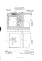
- Figure 1 is a front elevation of a refrigerator provided with the present invention
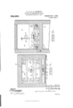
- Fig. 2 is a vertical section taken on line 2 2 of Fig. 1
- Fig. 3 is a section taken at right-angles to Fig. 2 on line 3 3 of that figure
- Fig. 4 is a section on line et--fl of Fig. 2 with the ice container removed
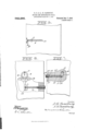
- Fig. 5 is a side elevation showing a slightly different form
- Fig. 6 is a side view showing a different form of indicator
- Fig. 7 is a sectional view through the adjusting screw, rod and spring.
- an ice box of the usual type having an upper interior chamber 9.
- the ice box has a front wall 10, side wall 11 and 12, and a back wall 13.
- brackets 15 which receive a horizontal rock shaft 16, extending at one end laterally beyond the adjacent bar 14, and having at this laterally extending portion a depending arm 17 to the lower portion of which there is pivoted a forwardly extending horizontal rod 18, having an enlargement 20 at its rearward end, resulting in a shoulder 19 surrounding the rod.
- An interiorly threaded sleeve 21 is carried b v the forward wall of the refrigerator, and engaged within this threaded sleeve there is a threaded plug 22, having an adjusting nger piece 23 at its outer end and having in its inner end face a longitudinally extending recess 24 which receives the outer end of the rod 18.
- a helical spring 25 is engaged with the rod 18 between the inner end of the plug 22 and the shoulder 19, and thus the arm 17 is held yieldably against forward movement at its lower end.
- the plug may be operated to vary the tension of the spring as will be readily understood.
- Each of the bars 11 has a pair of spaced upwardly directed fingers 26, one of these fingers 2G being located adjacent to each end of each bar, and these fingers are provided in their upper surface with arcuate sockets 27
- a pair of horizontal spaced members 27 and 28 are disposed above the bars 14, these members extending atl right angles to the bars, the member 27 being located adjacent to the forward wall of the refrigerator, and the member 28 being located adjacent to the rearward wall of the refrigerator.
- These members have outwardly directed laterally turned end portions 27 and 28 respectively, these end portions having depending feet 29 at their extremities which are rounded at their lower ends as shown at 30 and which are engaged in the sockets of the iingers 26, these sockets being indicated at 27.
- the curvature of the sockets is greater than the curvature of the feet 29, so that the feet are free to move pivotally within the sockets.
- the member 28 has a forwardly extending central yoke member 31, and the member 27 has a rearwardly extending arm 32 which is pivoted at its rearward end within the yoke member 31. This point of pivotal connection is thus movable vertically, the members 27 and 2S rocking upon their feet 29 as l vided with an upwardly extending fixed will be understood.
- a depending knife edge 33 is carried by the arm 32 alining vertically with the axis upon which the members 31 and 32 move with respect to each other and this knife edge is received in a clutch 34 formed in the upper end of an arm 35 extending vertically and having a forwardly turned lateral lower portion 3G adjoining the shaft 16.
- the vertical plane of the arm 35 is thus located rearwardly of the vertical plane of the shaft 16, so that when the arm 35 is moved downwardly, the shaft 16 will be rocked to move the arm 17 forwardly at its lower end against the action of the spring
- a forwardly extending lever 37 is carried by the shaft 16 and is thus movable vertically at its forward end.
- a vertical rack bar 38 is pivoted to the lever 37, for vertical movement therewith, and has its rack 33 meshed with a pinion 39 carrying a pointer 40, which is movable to indicate different points upon a circular scale 41 and thus indicate the weight of ice as will be later brought out.
- the pinion 39 is mounted upon a plate 42, which also carries a vertical scale 43, this scale being arranged parallel with the rack bar 38, and having extended thereover a pointer 45 which is carried by the rack bar.
- the scale 43 is marked to correspond with the proportionate contents of the refrigerator, so that by inspecting the scale 43 and the point indicated by the pointer 45, it may be ascertained whether the ice chamber.l to be later described, is one-third, one-half, or three-quarters full or the exact amount of ice contained therein as will be understood.
- the rack bar 3S includes a link 44, )ivotally connected with the lower portion of the rack bar and pivoted to the lever 37, for proper operation of the mechanism.
- a rectangular ice receiving member 47 has rounded feet 4S which are located in sockets 49 formed in the upper faces of the member 27 and 28, and it will be seen that the weight of ice within the receptacle 47 will cause the members 27 and 2S to rock upon their feet 29, thus moving the knife edge 33 downwardly and operating the indicating mechanism.
- Fig. 5 there is shown a form of the invention in which a ⁇ balance arm A is connected. with the shaft 16, and has a depending weight plate B and a sliding poise C.
- This balance arm may or may not be used in connection with the indicator described in the foregoing.
- Fig. G there is shown a different form of indicator, in which the shaft 1G, is proarm L having a rack segment M at its upper end, meshing with a pinion N, corresponding to the pinion 3S), and carrying a pointer P corresponding to the pointer 4() and movable over a circular scale 41.
- the arm 17 is omitted, and the rod 13 is pivoted directly to the upwardly extending arm L.
- a scale structure the combination with parallel members, of a transverse shaft pivotally connected with the members, upwardly extending projections carried by the members, said projections having arcuate sockets in their upper faces, a pair of spaced members disposed transversely of the supporting members and extending across the space between the supporting members, said second named members having outwardly turned end portions, depending rounded feet carried by the end portions and engaged in the sockets of the projections, in, wardly extending members carried by the second named members, said inwardly extending members being pivotally connected, said second named members having arcuate sockets in their upper faces inwardly of their feet, an ice receptacle having depending rounded projections engaged in the sockets of the second named members, a laterally and upwardly extending arm carried by the shaft, said arm having a notch at its upper end, a knife edge, connected with the pivoted members and resting in the notch of the arm, a lever connected with the shaft and extending oppositely from the arm, a rack bar connected with
Landscapes
- Engineering & Computer Science (AREA)
- Chemical & Material Sciences (AREA)
- Combustion & Propulsion (AREA)
- Physics & Mathematics (AREA)
- Mechanical Engineering (AREA)
- Thermal Sciences (AREA)
- General Engineering & Computer Science (AREA)
- A Measuring Device Byusing Mechanical Method (AREA)
Description
@zu H5 715.6117159 wor/mu D. G. & A. H. SANSBURY. ICE BOX AND RBFRIGERATOR SCALE.
APPLIGATIGN FILED Nov. 5, 1908.
Patented Dec. 7, 1909.
3 SHEETS-SHEET 1.
Anuniw. s. GRAHAM CQ. Pnu'rourm'aurxsns. msmmmu. n. c.
D. G. & A. H. SANSBURY.
1GB BOX AND RBPRIGBRATOR SCALE.
APPLICATION FILED NOV. 5, 1908.
Patented Dec. 7, 1909.
3 SHEETS-SHEET 2.
-mmlw af/@Zzzfy SH01/WNBA moksw, s. Gamm co.. More D. G. & A. H. SANSBURY.
ICB BOX AND REFRIGERATOR SCALE.
APFLIOATION z'ILnnNov. 5, 1908.
PatentedDec. 7, 1909.
3 SHEETS-SHEET 3.
UNITED STATES PATENT OFFICE.
DUDLEY Gr. SANSBURY AND ADELINE H. SANSBURY, OF BROOKLYN, NEW YORK.
ICE-BOX AND REFRIGERATOR SCALE.
To all whom t may concern.'
Be it known that we, DUDLEY Gs" SANsi-.URY and ADELINE H. SANSBURY, citizens of the United States, residing at Brooklyn, in the county of Kings and State of New York, have invented certain new and useful Imj provements in Ice-Box and Refrigerator Scales, of which the following is a speciiication.
This invention relates to scales and has for its object to provide a scale incorporated in a refrigerator and arranged to show the weight of ice containedwithin the refrigerator, thus making it possible to ascertain whetherI or not a proper quantity of ice has been deposited, and also to determine when a new supply of ice is needed.
Another object is to provide a scale arrangement which will be especially adapted for use in connection with a refrigerator', and which will be relatively simple and cheap.
Other objects and advantages will be apparent from the following description and it will be understood that changes in the specific structure shown and described may be made within the scope of the claims without departing from the spirit of the invention.
In the drawings forming a portion of this specification, and in which like characters of reference indicate similar parts in the several views, Figure 1 is a front elevation of a refrigerator provided with the present invention, Fig. 2 is a vertical section taken on line 2 2 of Fig. 1, Fig. 3 is a section taken at right-angles to Fig. 2 on line 3 3 of that figure, Fig. 4 is a section on line et--fl of Fig. 2 with the ice container removed, Fig. 5 is a side elevation showing a slightly different form, Fig. 6 is a side view showing a different form of indicator, Fig. 7 is a sectional view through the adjusting screw, rod and spring.
Referring now to the drawings, there is shown an ice box of the usual type, indicated at 8, having an upper interior chamber 9. The ice box has a front wall 10, side wall 11 and 12, and a back wall 13.
Secured at their ends to the front and back walls 10 and 13, there are a pair of horizontal parallel bars 14. These bars 14 have a pair of transversely alining depend- Specication of Letters Patent.
Application filed November 5, 1908.
Patented Deo. *7, 1909.
Serial No. 461,249.
ing brackets 15, which receive a horizontal rock shaft 16, extending at one end laterally beyond the adjacent bar 14, and having at this laterally extending portion a depending arm 17 to the lower portion of which there is pivoted a forwardly extending horizontal rod 18, having an enlargement 20 at its rearward end, resulting in a shoulder 19 surrounding the rod.
An interiorly threaded sleeve 21 is carried b v the forward wall of the refrigerator, and engaged within this threaded sleeve there is a threaded plug 22, having an adjusting nger piece 23 at its outer end and having in its inner end face a longitudinally extending recess 24 which receives the outer end of the rod 18. A helical spring 25 is engaged with the rod 18 between the inner end of the plug 22 and the shoulder 19, and thus the arm 17 is held yieldably against forward movement at its lower end. The plug may be operated to vary the tension of the spring as will be readily understood.
Each of the bars 11 has a pair of spaced upwardly directed fingers 26, one of these fingers 2G being located adjacent to each end of each bar, and these fingers are provided in their upper surface with arcuate sockets 27 A pair of horizontal spaced members 27 and 28 are disposed above the bars 14, these members extending atl right angles to the bars, the member 27 being located adjacent to the forward wall of the refrigerator, and the member 28 being located adjacent to the rearward wall of the refrigerator. These members have outwardly directed laterally turned end portions 27 and 28 respectively, these end portions having depending feet 29 at their extremities which are rounded at their lower ends as shown at 30 and which are engaged in the sockets of the iingers 26, these sockets being indicated at 27.
The curvature of the sockets is greater than the curvature of the feet 29, so that the feet are free to move pivotally within the sockets.
The member 28 has a forwardly extending central yoke member 31, and the member 27 has a rearwardly extending arm 32 which is pivoted at its rearward end within the yoke member 31. This point of pivotal connection is thus movable vertically, the members 27 and 2S rocking upon their feet 29 as l vided with an upwardly extending fixed will be understood.
A depending knife edge 33 is carried by the arm 32 alining vertically with the axis upon which the members 31 and 32 move with respect to each other and this knife edge is received in a clutch 34 formed in the upper end of an arm 35 extending vertically and having a forwardly turned lateral lower portion 3G adjoining the shaft 16. The vertical plane of the arm 35 is thus located rearwardly of the vertical plane of the shaft 16, so that when the arm 35 is moved downwardly, the shaft 16 will be rocked to move the arm 17 forwardly at its lower end against the action of the spring A forwardly extending lever 37 is carried by the shaft 16 and is thus movable vertically at its forward end. A vertical rack bar 38 is pivoted to the lever 37, for vertical movement therewith, and has its rack 33 meshed with a pinion 39 carrying a pointer 40, which is movable to indicate different points upon a circular scale 41 and thus indicate the weight of ice as will be later brought out.
The pinion 39 is mounted upon a plate 42, which also carries a vertical scale 43, this scale being arranged parallel with the rack bar 38, and having extended thereover a pointer 45 which is carried by the rack bar. The scale 43 is marked to correspond with the proportionate contents of the refrigerator, so that by inspecting the scale 43 and the point indicated by the pointer 45, it may be ascertained whether the ice chamber.l to be later described, is one-third, one-half, or three-quarters full or the exact amount of ice contained therein as will be understood. The rack bar 3S includes a link 44, )ivotally connected with the lower portion of the rack bar and pivoted to the lever 37, for proper operation of the mechanism.
A rectangular ice receiving member 47 has rounded feet 4S which are located in sockets 49 formed in the upper faces of the member 27 and 28, and it will be seen that the weight of ice within the receptacle 47 will cause the members 27 and 2S to rock upon their feet 29, thus moving the knife edge 33 downwardly and operating the indicating mechanism.
Suitable drain and air circulating openings will of course be provided, as will be understood. y
In Fig. 5 there is shown a form of the invention in which a`balance arm A is connected. with the shaft 16, and has a depending weight plate B and a sliding poise C. This balance arm may or may not be used in connection with the indicator described in the foregoing.
In Fig. G, there is shown a different form of indicator, in which the shaft 1G, is proarm L having a rack segment M at its upper end, meshing with a pinion N, corresponding to the pinion 3S), and carrying a pointer P corresponding to the pointer 4() and movable over a circular scale 41. In this form of the invention, the arm 17 is omitted, and the rod 13 is pivoted directly to the upwardly extending arm L.
lVhat is claimed is:-
1. The combination with an ice box, of a pair of supporting bars mounted therein, said supporting bars having sockets in their upper faces, a pair of pivotally connected members, rounded feet carried by the pivotally connected members and engaged in the sockets, the pivot point of the members lying inwardly of the feet, a shaft pivotally connected with the supporting bars for rocking movement, connections between the pivot point of the two members and the shaft for rotation of the shaft when the pivot point is mounted down iardly, an indicator mounted upon the outer surface of the ice box, connections between the indicator and the shaft for operation of the indicator when the shaft is rocked, and adjustable means for holding the shaft yieldably against rocking motion.
2. 1n a scale structure, the combination with parallel members, of a transverse shaft pivotally connected with the members, upwardly extending projections carried by the members, said projections having arcuate sockets in their upper faces, a pair of spaced members disposed transversely of the supporting members and extending across the space between the supporting members, said second named members having outwardly turned end portions, depending rounded feet carried by the end portions and engaged in the sockets of the projections, in, wardly extending members carried by the second named members, said inwardly extending members being pivotally connected, said second named members having arcuate sockets in their upper faces inwardly of their feet, an ice receptacle having depending rounded projections engaged in the sockets of the second named members, a laterally and upwardly extending arm carried by the shaft, said arm having a notch at its upper end, a knife edge, connected with the pivoted members and resting in the notch of the arm, a lever connected with the shaft and extending oppositely from the arm, a rack bar connected with the lever and extending upwardly therefrom, an indicator connected with the rack bar, said indicator being arranged to show the weight of matter within the receptacle, a scale located adjacent to the rack bar, a pointer carried by the rack bar and arranged to indicate ditlerent points upon the scale, a depending arm carried by the shaft, a forwardly extending In testimony whereof we aliix our signarod pivotally connected with the depending tures, in presence of two witnesses.
arm, a helical spring engaged with the rod DUDLEY G. SANSBURY. :1nd arranged to hold the lower end of the ADELINE H. SANSBURY. depending arm against forward movement, lVitnesses:
and inea-ns for varying the tension of the DETEEF LASSEN,
snin HARRY Or' ENS.
Priority Applications (1)
| Application Number | Priority Date | Filing Date | Title |
|---|---|---|---|
| US46124908A US942286A (en) | 1908-11-05 | 1908-11-05 | Ice-box and refrigerator scale. |
Applications Claiming Priority (1)
| Application Number | Priority Date | Filing Date | Title |
|---|---|---|---|
| US46124908A US942286A (en) | 1908-11-05 | 1908-11-05 | Ice-box and refrigerator scale. |
Publications (1)
| Publication Number | Publication Date |
|---|---|
| US942286A true US942286A (en) | 1909-12-07 |
Family
ID=3010708
Family Applications (1)
| Application Number | Title | Priority Date | Filing Date |
|---|---|---|---|
| US46124908A Expired - Lifetime US942286A (en) | 1908-11-05 | 1908-11-05 | Ice-box and refrigerator scale. |
Country Status (1)
| Country | Link |
|---|---|
| US (1) | US942286A (en) |
Cited By (2)
| Publication number | Priority date | Publication date | Assignee | Title |
|---|---|---|---|---|
| US2447335A (en) * | 1946-03-06 | 1948-08-17 | Philco Corp | Refrigerating apparatus with means for indicating the quantity of solid refrigerant therein |
| US8328438B2 (en) | 2011-03-10 | 2012-12-11 | Spinnaker Process Instruments | Networked freezer stocking management |
-
1908
- 1908-11-05 US US46124908A patent/US942286A/en not_active Expired - Lifetime
Cited By (3)
| Publication number | Priority date | Publication date | Assignee | Title |
|---|---|---|---|---|
| US2447335A (en) * | 1946-03-06 | 1948-08-17 | Philco Corp | Refrigerating apparatus with means for indicating the quantity of solid refrigerant therein |
| US8328438B2 (en) | 2011-03-10 | 2012-12-11 | Spinnaker Process Instruments | Networked freezer stocking management |
| US8545113B2 (en) | 2011-03-10 | 2013-10-01 | Spinnaker Process Instruments | Networked freezer stocking management |
Similar Documents
| Publication | Publication Date | Title |
|---|---|---|
| US1183638A (en) | Device for indicating the list of vessels. | |
| US715582A (en) | Test-indicator. | |
| US748297A (en) | Weighing attachment for refrigerators. | |
| US1249927A (en) | Scale. | |
| US762010A (en) | Gage. | |
| US922960A (en) | Level. | |
| US942945A (en) | Scale. | |
| US1143109A (en) | Measuring device. | |
| US1523168A (en) | Gasoline gauge | |
| US1146975A (en) | Counting apparatus. | |
| US1748351A (en) | Scale | |
| US1190632A (en) | Support for fire-pails and the like. | |
| US1516405A (en) | Scale construction | |
| US928491A (en) | Weighing-machine. | |
| US1094722A (en) | Scale-beam. | |
| US745684A (en) | Spring-scale. | |
| US765146A (en) | Weighing attachment for refrigerators. | |
| US738572A (en) | Store-bin. | |
| US939213A (en) | Scale. | |
| US1222488A (en) | Refrigerator-scale. | |
| US312743A (en) | Combined square | |
| US555661A (en) | Weighing-scale | |
| US895692A (en) | Bearing for scale-beams. | |
| USRE5082E (en) | Improvement in spring-scales | |
| US1318932A (en) | Lubricating system |