US942091A - Harmonic signaling system. - Google Patents
Harmonic signaling system. Download PDFInfo
- Publication number
- US942091A US942091A US30012506A US1906300125A US942091A US 942091 A US942091 A US 942091A US 30012506 A US30012506 A US 30012506A US 1906300125 A US1906300125 A US 1906300125A US 942091 A US942091 A US 942091A
- Authority
- US
- United States
- Prior art keywords
- current
- source
- circuit
- battery
- waves
- Prior art date
- Legal status (The legal status is an assumption and is not a legal conclusion. Google has not performed a legal analysis and makes no representation as to the accuracy of the status listed.)
- Expired - Lifetime
Links
- 230000011664 signaling Effects 0.000 title description 11
- 230000005540 biological transmission Effects 0.000 description 22
- 230000000694 effects Effects 0.000 description 9
- 230000000737 periodic effect Effects 0.000 description 8
- 230000000153 supplemental effect Effects 0.000 description 5
- 239000004020 conductor Substances 0.000 description 4
- 238000010586 diagram Methods 0.000 description 3
- 230000010349 pulsation Effects 0.000 description 3
- 230000000979 retarding effect Effects 0.000 description 3
- 239000013589 supplement Substances 0.000 description 3
- 238000013016 damping Methods 0.000 description 2
- 230000001939 inductive effect Effects 0.000 description 2
- 230000007246 mechanism Effects 0.000 description 2
- 241001506137 Rapa Species 0.000 description 1
- 230000009471 action Effects 0.000 description 1
- 230000007547 defect Effects 0.000 description 1
- 230000007812 deficiency Effects 0.000 description 1
- NRUQNUIWEUZVLI-UHFFFAOYSA-O diethanolammonium nitrate Chemical compound [O-][N+]([O-])=O.OCC[NH2+]CCO NRUQNUIWEUZVLI-UHFFFAOYSA-O 0.000 description 1
- 230000002452 interceptive effect Effects 0.000 description 1
- 230000004048 modification Effects 0.000 description 1
- 238000012986 modification Methods 0.000 description 1
- QEVHRUUCFGRFIF-MDEJGZGSSA-N reserpine Chemical compound O([C@H]1[C@@H]([C@H]([C@H]2C[C@@H]3C4=C(C5=CC=C(OC)C=C5N4)CCN3C[C@H]2C1)C(=O)OC)OC)C(=O)C1=CC(OC)=C(OC)C(OC)=C1 QEVHRUUCFGRFIF-MDEJGZGSSA-N 0.000 description 1
- 230000002441 reversible effect Effects 0.000 description 1
- 230000009291 secondary effect Effects 0.000 description 1
- 230000001502 supplementing effect Effects 0.000 description 1
- 230000001360 synchronised effect Effects 0.000 description 1
- 238000004804 winding Methods 0.000 description 1
Images

Classifications
-
- H—ELECTRICITY
- H04—ELECTRIC COMMUNICATION TECHNIQUE
- H04Q—SELECTING
- H04Q3/00—Selecting arrangements
Definitions
- ELYBIA OHIO, ASSIGNOR 'ro DEAN ntno'rnic comraur, or ELYRIA, omo, a coaroaarrou or onto.
- My invention relates to signal systems, and more particularly to what are known as harmonic selective signaling systems, wherein a lurality of stations are served, or a plum ity of signals may be actuated over a single circuit.
- My invention finds its principal use at present, and I shall therefore illustrate and describe it as embodied, in a party-line telephone system; but it will sufliciently appear from both illustration and description that it is equally a)plicable to any other class of systems w erein the same kind of current is employed.
- pole-changers to 1 supply currents of different frequencies for sitgnaling 'over tele hone lines
- the source 0 current supply or these pole-changers is conveniently arranged to be the main stora e battery of the exchange equipment.
- T l is battery also supplies current or incoming signals, and for the transmitters employed both at the central office and at the subscribers stations. It is therefore very important to prevent the accession of any rapidly recurring changes in otential which would tend to make lines noisy.
- the vibrating ole-chan ers if connected directly to the main battery busses, have a tendency to produce noise in the subscribers lines connected to said basses, and this is particularly so where the store e battery is smaller is comparatively 01.; that is where its internal resistance is not of the lowest, or its output of current ample for all purposes.
- auxiliary source is not necessarily-a storage battery
- a generator may be employed in its place, of any de-" sired and suitable type, and a driven generator may also be employedin place of a battery I01 the mam source.
- a generator may be employed in its place, of any de-" sired and suitable type, and a driven generator may also be employedin place of a battery I01 the mam source.
- the character of the source will necessarily be varied according to the character and requirements of the system'.
- the gist of the invention lies in'the employment of a source of current with associatcd parts so constructed as to deliver energy in successive waves or increments, t'o gether with means for acceutuat-mg the said waves, preferably by boosting the available i electromotive force for each recurring wave.
- the 1n ⁇ -'cn"t1c-n serves its end; but it wll also serve in the case where the main source itself is not capable of supplya ing sharp pulsations.
- the auxintending to cover all the applications of circuits of a manual telephone switchboard,
- iliary source may then be associated with the alternator so as to furnish the boosting electromotiveforces and current through a commutator or pole-changer running synchronously with the rotor of the alternator. Since the invention may therefore be applied reversely in a sense as to the functions subserved, and since I believe myself to be the first to produce a successful arrangement of this kind, I shall claim the same broadly,
- auxiliary battery of ordinary dry cells which of course are commonly employed only in open circuit work. I have found them eminently satisfactory for my purposes, and that they stand up well, because they are normally exposed to a counter e. m. f. which prevents flow as well as an open circuit. In fact, they work better than under ordinary conditions, because the counter e. nnf, tends to depolarize and restore them constantly, thus keeping their voltage up to normal.
- Wl1lCl1- Figure 1 is a diagram showing two cordequippedwith selective keys, and supplied with ringing current of four frequencies from mam and auxiliary batteries;
- Fig. 2 is a diagram of a modification.
- a'ringing key, K, and nset of selective keys is, k, 70's; lVhen'the plug, 1 has been in; sorted in a line jacln'and the'pperator de- ⁇ sires' to' call one of four parties on thatline,
- eaaoei combine these so that when any selective key is operated it automatically operates the
- the latter breaks the cordcircuit, connects the sleeve of the plug to the wire 7 and thence through wire 5 to the .main battery, B, and at the same time grounds a wire, 8, which is common to all of the cord-circuit ringing keys and constitutes the controlling wire for the polechanger set.
- the sleeve of the plug is connected to battery in order that direct current may be supplied to hold up the cut-off relay of the line, since the cord-circuit is severed at the key, and the flow of battery current would othcrwisebc interrupted.
- the ringing current flows out over the tip side of the )lu to line back throu h the sleeve side of line and plug and to ground through the battery, B.
- the wire 8 leads to the common relay, R, which controls ringing current to all of the pole-changing units, U, U, U U.
- R the relay connected through the wire 9 to the retardation coil, M, and thence by wire 10 to the main battery. Whenever the wire 8 is grounded, therefore, a circuit will be completed from the main battery through the relay, R, and the latter will pull up.
- Each pole-changer has a vibrating magnet, N, whose armature, it, carries a pendulum rod and a Weight or pendulum bob, a.
- Each armature also carries three contactsprings, n a a, the springs, 72 being in- 'sulated-and the others connected to the lever,
- auxiliary battery, B I make in practice a primary battery or a storage battery of small ampere capacity, and during operation it is kept constant y charged, since it is floated across the terminals of the main battery and subject to the damping effects of the retardation coil,
- .M has a constant difference of potential across its terminals. It should be noted particularly that this retardation coil, M, is in the circuit between the main battery and the vibrators, U, etc., while the connection of u 1 i u I the auxiliary battery to the springs, n is direct. The effect of this is as follows: The armature of relay, R, being up, current flows through the primary winding, t, of each transformer from B, 10, M, 9, 13, 1', 12, a, 18 or 19, t, 19, or 18, a1, a, 11 and back to battery. As the armature, n, is vibrating back and forth, this circuit is made and' broken a number of times per second corcuits connected to the battery bus 5.
- the secondary effects produced by the transformers, T, are smoother than those in the primary in any event, and with the retardation coil, M, in the primary circuit the waves become so much flattened and smoothed off as to reduce the efficiency of ringing.
- the battery, B remedies this.
- the difference of potential between the wires 11 and 9 is at a maximum, the battery B sup lies practically no current, but when, t e circuit having been closed at the'contacts, a 17, for an instant so that the electromotive force should be a maximum, but is not owing to the choking effect of the coil, M, then the battery B for a very brief interval carries the load, furnishing what I may call the peak of the wave.
- the battery may be called an equalizer, since it really takes up and absorbs the noisy back surgings, but I prefer to call it a peak battery because it accentuates or boosts the otherwise flattened Waves.
- the auxiliary battery, B, and the coil, M, ttorm apart of the equipment the main terminals for battery connection in the exchange being as indicated by the letters, 0:.
- Suitable binding-posts or other terminals are also provided for the ringing leads and the wires 8, and within these terminals all the circuits and the apparatus herein shown are connected up complete and selfcontained.
- the entire equipment is preferably housed in a cabinet provided with a shelf or other supporting means for the battery, B.
- Fig. 2 shows a form of circuit and an arrangement of the apparatus which is even simpler than that of Fig. 1. In this case,
- the ma I nets, N are wound so as to have a ver hig resistance, and hence theytake so htt e ourrent that they have no disturbing effect on r of the vibrators.
- FIG. 2 may be regarded as showing a very simple embodiment of the invention.
- circuit, alternating current translating devices thereon, commutating means and a plu- 'rality of sources of direct currentsupply for said commutatmg means comprising a mam source adapted to supply bulk energy ,and
- one or more supplementalsources adapted to directly modify the electromotive force so to produce accentuated waves.
- a circuit alternating current translating devices thereon, a pole-changer connected therewith, a main source of continuous current connected to said pole-changer through a retardation coil, and a supplen'iental source connected to the polechanger direct.
- a ci.rcuit one or more signal receiving devices thereon, a pole-changer connected therewith, a main battery connected to said polcchanger through a retardation coil, and a supplemental battery connected thereto direct, whereby accentuated waves of current are produced in the circuit without any sharp changes of potential in the main battery connections.
- a main source of current supply a plurality of circuits having both alternating and direct current translating devices thereon, commutating devices for the alternating cub rent circuits, means interposed between the main source and said commutating devices to prevent any abrupt changes on the terminals of said main source, and a supplemental source connected to the commutating devices to furnish accentuated electromotive forces thereto.
- a main source of current supplying a plurality of circuits having both alternating and di rect current t 'anslating devices thereon, commutating devices for the alternating current circuits, means interposed between the main source and said con'n'i'iutating devices to prevent any abrupt changes on the terminals of said main source, and a supplemental source comprising a storage battery adapted to be charged by the main source and to discharge through the conunutating dcriccs so as to produce accentuated current waves.
- a pole-changer associated .with said source to furnish modified signaling current, aretardation coil connected between the pole changer and the source lo prevent noise onthe talking circuits, and a supplemental source of current connected to the pole-changer between it and the retardation coil, so as to compensate for the loss of sharpness due to the coil.
- a linecircuit and a plurality of harmonic signaling devices connected thereto, a main battery supplying current for both lalking aiul vicesthereon, a pole-changing device, and a signaling purposes, a plurality of polechangers connected to said main battery to derive current therefrom throu h a retardation coil, and a su plemental attery connected to the pole-9 an ers direct, so as to sharpen the waves produced.
- a source of current means in circuit with such source for modifying the form of current waves delivered by such source to such circuit and a second source of current adapted to correct such modified current waves.
- a source of current means in circuit with such source for flattening the current waves delivered by suchsource to such circuit and a second source of current adapted to correct such flattened current waves.
- a source of current means] in circuit with such source for modifying the form of cur- .rent waves delivered by such source to such circuitv and a battery adapted to supplement such modified current waves, such battery adapted to be automatically charged from such source of current.
- a source of electric energy means in circuit with such-source for retarding the flow of periodic currents therefrom, translatin means in such circuit adapted to be operated by periodic currents and a second source of electric energyadapted to supply current periodically to such circuit, such currents thus supplied to such circuit adapted to comhim to effectively operate such translating means.
- a source of electric energy means in circuit with such source for retarding the flow of periodic currents therefrom translating means in' such circuit adapte to be operated b periodic currents and a battery adapte to sup ly current periodically to such circuit, suc h currents thus supplied to such circuit ada ted to combine to effectively operate suc translatin means, such battery adapted to be automatically charged from such source of current.
- I a circuit containing translating means adapted to be operated by periodic currents, two sources of electric ener current to such circuit in periodic waves and means located between such sources'of electric energy for modifying current waves delivered from one of such sources to such circuit, the resultant of such combined current waves adapted to efi'ectively operate such translating means.
- a source of current In an electrical transm sslon system, a source of current, a circuit for delivering cuit for causing the waves delivered there through to thecircuit to have a form different than such waves would assume in the absence of such modifyin means, and a second source of current electrically connected to such circuit adapted to effect further thereirom.
- a source of current conductors extending therefrom, means electrically connect d with the conductors for nodifymg the i" rm of current waves delivered from such source to rent electrically connected to the conductors for supplementing such current waves.
- Inzan electrical transr'nission system a source of current of practically constant potential, means in circuit with such source for sending current in waves through the circuit, means in the circuit for modifying theform of the current waves thus roduced, and a second source of current adapted to correct such modified waves.
- a source of current of practically constant potential means in circuit with such source for sending current in; waves through the the form of the current waves thus produced, and a second source of current electrically connected to the circuit and adapted to supplement such modified waves.
- a source of current In an electrical transmission system, a source of current, a circuit extending therefrom, means for delivering current from such source through the circuit in waves, retardation mechanism associated with the circuit to modify the form of the current waves delivered to the circuit, and a second source of current adapted to correct the modified current waves.
- a source of current In an electrical transmission system, a source of current, a circuit extending therefrom, means for delivering current from such source through the circuit in waves, retardation mechanism. electrically connected with the circuit to modify the form of the current waves delivered-to the circuit, and a second source of current electrically connected to the circuit and adapted to supplement the modified current waves.
- a direct current battery In an electrical transmission system, a direct current battery, a circuit extending therefrom, means in the circuit for causing current to flow from such battery in waves,
- a direct current battery In an electrical transmission system, a direct current battery, a circuit extending therefrom, means in the circuit for causing current to flow from such battery in Waves, retardation means electrically connected with the circuit to modify the form of such current waves, and a second direct current battery electrically connected to the circuit and adapted to correct such modified Waves.
- a source oi. current
- a current converter adapted to convert continuous to alternating currents in circuit with said source
- a choking device adapted to eliminate buttery disturbing effects in circuit with said source
- a second source of current floated across the terminals of the first source adapted to correct the current Waves modified by the choking device.
Landscapes
- Engineering & Computer Science (AREA)
- Computer Networks & Wireless Communication (AREA)
- Charge And Discharge Circuits For Batteries Or The Like (AREA)
Description
R. H. MANSON.
HARMONIG SIGNALING SYSTEM.
APPLICATION FILED FEB. 8, 1906.
Patented Dec. 7, 1909:
2 SHEETS-SHEET 1.
wi Hume:
- R. H. MANSON. HARMONIG SIGNALING SYSTEM.
APPLICATION FILED FEB. 8, 1906.
Patented Dec. 7, 1909.
2 SHEETS-SHEET 2;
M RW .I. #333 R m M m w RAY H. MANSON, or
ELYBIA, OHIO, ASSIGNOR 'ro DEAN ntno'rnic comraur, or ELYRIA, omo, a coaroaarrou or onto.
HABMONIC SIGNALING SYSTEM.
To all whom it may concern:
Be it known that I, RAY H. MANSON, a citizen of the United States, residin at Elyria, in the county of Lorain and tate of Ohio, have invented certain new and useful Improvements in Harmonic Signaling Systems, of which the following is a specification, reference being had therein to the accompanying drawing.
My invention relates to signal systems, and more particularly to what are known as harmonic selective signaling systems, wherein a lurality of stations are served, or a plum ity of signals may be actuated over a single circuit.
My invention finds its principal use at present, and I shall therefore illustrate and describe it as embodied, in a party-line telephone system; but it will sufliciently appear from both illustration and description that it is equally a)plicable to any other class of systems w erein the same kind of current is employed.
It hasheretofore been proposed to employ what are known as pole-changers to 1 supply currents of different frequencies for sitgnaling 'over tele hone lines, The source 0 current supply or these pole-changers is conveniently arranged to be the main stora e battery of the exchange equipment. T l is battery also supplies current or incoming signals, and for the transmitters employed both at the central office and at the subscribers stations. It is therefore very important to prevent the accession of any rapidly recurring changes in otential which would tend to make lines noisy. The vibrating ole-chan ers, if connected directly to the main battery busses, have a tendency to produce noise in the subscribers lines connected to said basses, and this is particularly so where the store e battery is smaller is comparatively 01.; that is where its internal resistance is not of the lowest, or its output of current ample for all purposes. In order to prevent this noise, I ropose inserting a choking coil in the su p y or feed wire between the battery mdt e pole-changers; but if this coil be included without any further provision, and if it after sufiicient retardation to currents of the frequencies dealt with in the polechan ers to prevent substantial lea age thereiirom into the talking circuits, then t e efficiency of the pole-changers is reduced to Specification of Letters ratent. Patented Dec. 7, 1909. Application filed February a, 1900. Serial No. 300,125. I
i a marked degree: This is due to the fact that the peaks'or crests of the successive waves are smoothed off, and the current curve is very much flattened and reduced below the shape and dimensions which give the best results in ringing. The amount of energy supplied from the main battery is substantially sufficient for the purpose, but it is no longer applied in the most etlicient manner. In order to remedy this defect, and according to the present. invention, I supply an auxiliary source, which may be a small storage battery or its equivalent, bridged or floated across the main battery wires, between the retardation coil and the pole-changers. Like poles of this battery and the main battery are connected to the same wires, so that the auxiliary is kept constantly charged, and in fact is called upon for no discharge except when the electromotive force due to the main battery is choked down and prevented from producing a peak current, the deficiency beingthen momentarily supplied for'eaehwave by the auxiliary battery. 1
It will be observed that the auxiliary source is not necessarily-a storage battery,
nor indeed a battery at all. A generator may be employed in its place, of any de-" sired and suitable type, and a driven generator may also be employedin place of a battery I01 the mam source. In fact, in
applying the invention in its broadest as-" pect to transmission systems-other than such as I describe herein, the character of the source will necessarily be varied according to the character and requirements of the system'. The gist of the invention lies in'the employment of a source of current with associatcd parts so constructed as to deliver energy in successive waves or increments, t'o gether with means for acceutuat-mg the said waves, preferably by boosting the available i electromotive force for each recurring wave. Where-the main source of current is one like with a steady an continuous supply for other pur )oses, the 1n\-'cn"t1c-n serves its end; but it wll also serve in the case where the main source itself is not capable of supplya ing sharp pulsations. Assuming, for example, that an alternator of or inary design with collector rings be substituted for the main battery and pole-changer, the auxintending to cover all the applications of circuits of a manual telephone switchboard,
fully describe the mechanical structures,
6 Each calling p'lug, P has associ'ated .with it she actuates one of the selective keys, is, is",
iliary source may then be associated with the alternator so as to furnish the boosting electromotiveforces and current through a commutator or pole-changer running synchronously with the rotor of the alternator. Since the invention may therefore be applied reversely in a sense as to the functions subserved, and since I believe myself to be the first to produce a successful arrangement of this kind, I shall claim the same broadly,
which itis capable, whether described herein or not.
- In a number of telephone systems equipped with improved ringing means according to the present invention, I have made the auxiliary battery of ordinary dry cells, which of course are commonly employed only in open circuit work. I have found them eminently satisfactory for my purposes, and that they stand up well, because they are normally exposed to a counter e. m. f. which prevents flow as well as an open circuit. In fact, they work better than under ordinary conditions, because the counter e. nnf, tends to depolarize and restore them constantly, thus keeping their voltage up to normal.
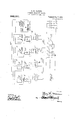
My invention is illustrated as to the specific embodiment hereinbefore mentioned, in the accompanying drawing, in Wl1lCl1- Figure 1 is a diagram showing two cordequippedwith selective keys, and supplied with ringing current of four frequencies from mam and auxiliary batteries; Fig. 2 is a diagram of a modification.
I do not consider it necessary herein to such as the pole-changers, relays and'transformers, of which I make use,'since these of themselves form no part of my present invention, and since they are fully described and claimed in a prior application filed by me on the 16th day of January, 1906, Serial No. 296,309. g I I Referring to Fig. l, P, P.,',rep r -sent answering and calling plugs d signed to co operate respectively with'thfe a swering and calling or trunk-jacks off'aima'l ial'switchonnected by bridged through the wiresi56 so as to supply. talking and signaling current to the cords and the lines interconnected .thereby.
a'ringing key, K, and nset of selective keys," is, k, 70's; lVhen'the plug, 1 has been in; sorted in a line jacln'and the'pperator de-{ sires' to' call one of four parties on thatline,
etc., and the'master key, K. I preferably master key;
eaaoei combine these so that when any selective key is operated it automatically operates the The latter breaks the cordcircuit, connects the sleeve of the plug to the wire 7 and thence through wire 5 to the .main battery, B, and at the same time grounds a wire, 8, which is common to all of the cord-circuit ringing keys and constitutes the controlling wire for the polechanger set. The sleeve of the plug is connected to battery in order that direct current may be supplied to hold up the cut-off relay of the line, since the cord-circuit is severed at the key, and the flow of battery current would othcrwisebc interrupted. The ringing current flows out over the tip side of the )lu to line back throu h the sleeve side of line and plug and to ground through the battery, B.
The wire 8 leads to the common relay, R, which controls ringing current to all of the pole-changing units, U, U, U U. On the other side the relay connected through the wire 9 to the retardation coil, M, and thence by wire 10 to the main battery. Whenever the wire 8 is grounded, therefore, a circuit will be completed from the main battery through the relay, R, and the latter will pull up.
Each pole-changer has a vibrating magnet, N, whose armature, it, carries a pendulum rod and a Weight or pendulum bob, a. Each armature also carries three contactsprings, n a a, the springs, 72 being in- 'sulated-and the others connected to the lever,
which is itself connected by the wire 11 to ground. The spring, a of every polechanger is connected through wire 12 to the armature, 9", of the relay, R, and when the latter is attracted, to a main battery wire 9 through the branch 13, also to the auxiliary battery wire 14-, leading to the auxiliary battery B.
t will be observed hat the circuit of each vibrating magnet, Y iscompleted as follows: B, 10, M, 9, 15, N, 16, 17, a 11 back to battery. The armatures arekept constantly vibrating, in this simple form of circuit, but may be separately controlled. by
suitable relays, as specified in my former- 'dilfere'nt" eri'ods of vibration. As each bob vibrates moves the spriiws, 77;, 775*, back and forth between fixed contacts so as to reverse"tlieconnection of the wires 1.1, 12 -'-to thewires 18, 19. By this means battery currentfiowing through these wires 1s rapa normally closed shunt containing non-inductive resistance. Any excessive current in a ringing lead will vibrate the corresponding armature to break the shunt and expose the inductive'resistance of its electromagnet. Y
It will be observed that whenever a key, 70, is operated to ring over a subscribers' line, the relay R pulls up and puts both main and auxiliary batteries on the contactsprings, W. The auxiliary battery, B, I make in practice a primary battery or a storage battery of small ampere capacity, and during operation it is kept constant y charged, since it is floated across the terminals of the main battery and subject to the damping effects of the retardation coil,
.M, has a constant difference of potential across its terminals. It should be noted particularly that this retardation coil, M, is in the circuit between the main battery and the vibrators, U, etc., while the connection of u 1 i u I the auxiliary battery to the springs, n is direct. The effect of this is as follows: The armature of relay, R, being up, current flows through the primary winding, t, of each transformer from B, 10, M, 9, 13, 1', 12, a, 18 or 19, t, 19, or 18, a1, a, 11 and back to battery. As the armature, n, is vibrating back and forth, this circuit is made and' broken a number of times per second corcuits connected to the battery bus 5.
responding to the tuned'period of the vibrating parts; and if the retardation 0011, M, were not included in the circuit sharp pulsations of current in the primary, it, would be produced. Under such conditions, however, and particularly where the storage battery B is a small one or rather old, I- t have ound that these pulsations react, prosmall periodic surgings in other cir- This will be understood if it be assumed that the two cord-circuits shown in the drawing are connected to two pairs of lines, and only one of them is being used for ringing. Where-the storage battery B has ample capacity, and has a normal y low internal re-. sistunce, with good terminal connections, no interfering efieet would be erceptible; but under the conditions named other circuits connected to the bus 5 may be rendered ducing .noisy while ringing 'is going on over any circuit. It is to obviate this that the retardation coil, M, is introduced. This has a good magnetic circuit, preferably closed as shown, and is wound so as to have a somewhat high coefficient of self-induction. The result is that it chokes out current changes of. frequencies within reasonable predetermined limits, but in choking these back from the battery bus 5 it also has a very perceptible damping effect on the current waves in the primary circuit I have traced. The secondary effects produced by the transformers, T, are smoother than those in the primary in any event, and with the retardation coil, M, in the primary circuit the waves become so much flattened and smoothed off as to reduce the efficiency of ringing. The battery, B, however, remedies this. When the difference of potential between the wires 11 and 9is at a maximum, the battery B sup lies practically no current, but when, t e circuit having been closed at the'contacts, a 17, for an instant so that the electromotive force should be a maximum, but is not owing to the choking effect of the coil, M, then the battery B for a very brief interval carries the load, furnishing what I may call the peak of the wave. Although I ive this explanation of the action of the attery, B, it may be stated in other words. The battery may be called an equalizer, since it really takes up and absorbs the noisy back surgings, but I prefer to call it a peak battery because it accentuates or boosts the otherwise flattened Waves.
\Vith the arrangement thus described, I find that my pole-changing sets may be iiistalled-in any exchange, even those of limited size, wherein the batteries have been in use for a long time, without making the lines in the least noisy.-
In furnishing equipments embodying this invention, the auxiliary battery, B, and the coil, M, ttorm apart of the equipment, the main terminals for battery connection in the exchange being as indicated by the letters, 0:. Suitable binding-posts or other terminals are also provided for the ringing leads and the wires 8, and within these terminals all the circuits and the apparatus herein shown are connected up complete and selfcontained. The entire equipment is preferably housed in a cabinet provided with a shelf or other supporting means for the battery, B.
Fig. 2 shows a form of circuit and an arrangement of the apparatus which is even simpler than that of Fig. 1. In this case,
ininal of the main battery, B. The ma I nets, N, are wound so as to have a ver hig resistance, and hence theytake so htt e ourrent that they have no disturbing effect on r of the vibrators.
the talking circuits. I have found it advisable to. make this direct connection to the main battery in some cases, in order to avoid any slowing down of the vibrators when a heavy load is put onto the transformers, i. 0., a greater load than the output of the auxiliary battery can conveniently take care of. Under such. circun'istances, with the arrangement of Fig. l, the resistance of the coil, M, would limit the flow of currentfrom the main battery, and the. lowering of potential would be suliicieut to weaken the movements I Gt course, this can only occur in cases of extreme load, but I have planned my circuits so that they are adapted to produce the most efficient results even'in emergencies. It will. also be observed in Fig. 2 that the leads 20, 21, 22 and 23 go directly .to the selective ringing. keys, is, is, c c and that instead oi having a separate master key, K, I ground the sleeve side of the plug through any one of the selective key, springs. Any suitable connection of ground or battery can be employed at this point.
The diagram of Fig. 2 may be regarded as showing a very simple embodiment of the invention.
Having thus described my invention What I claim and desire to secure by Letters Patent is 1 In an electrical transmission system, translating devices, a circuit therefor, a main source of current for the circuit for supplying energy thereto in quantity, an energy storing or retarding device between said main source and the transmision circuit, whereby a comparatively smooth flow of current is produced, together with a supplen'iental source connected outside of the energy storing device, and adapted to impress sharply varying periodic waves of clectromotive force upon the circuit, as to accentuate the eli'ects due to the main source.
In an electrical transmission system, a *ircuit and alternating current translating; devices therefor, a main source oli current for the circuit supplying energy thereto in flattened waves, and a supplemental source adapted to impress synchronous accentuating waves on the circuit. 7
3. In an electrical transmission system, a
"circuit, alternating current translating devices thereon, commutating means and a plu- 'rality of sources of direct currentsupply for said commutatmg means, comprising a mam source adapted to supply bulk energy ,and
one or more supplementalsources adapted to directly modify the electromotive force so to produce accentuated waves.
4;. In an electrical transmission system a circuit, alternating current translating deplurality of current sources therefor, adapt-- ed to have their electromotive forces and currents combined through said pole-changer to produce resultant effects in the line and translating devices.
5. In an electrical transmission system a circuit, alternating current translating devices thereon, a pole-changer connected therewith, a main source of continuous current connected to said pole-changer through a retardation coil, and a supplen'iental source connected to the polechanger direct.
6. In an electrical signaling system a ci.rcuit, one or more signal receiving devices thereon, a pole-changer connected therewith, a main battery connected to said polcchanger through a retardation coil, and a supplemental battery connected thereto direct, whereby accentuated waves of current are produced in the circuit without any sharp changes of potential in the main battery connections.
7. In an electrical transmission system, a main source of current supply, a plurality of circuits having both alternating and direct current translating devices thereon, commutating devices for the alternating cub rent circuits, means interposed between the main source and said commutating devices to prevent any abrupt changes on the terminals of said main source, and a supplemental source connected to the commutating devices to furnish accentuated electromotive forces thereto.
8. In an electrical transmission system a main source of current supplying a plurality of circuits having both alternating and di rect current t 'anslating devices thereon, commutating devices for the alternating current circuits, means interposed between the main source and said con'n'i'iutating devices to prevent any abrupt changes on the terminals of said main source, and a supplemental source comprising a storage battery adapted to be charged by the main source and to discharge through the conunutating dcriccs so as to produce accentuated current waves.
9. In a telephone exchange system a plurality of circuits and a main source of currentsupply therefor for both talking and signaling purposes, a pole-changer associated .with said source to furnish modified signaling current, aretardation coil connected between the pole changer and the source lo prevent noise onthe talking circuits, and a supplemental source of current connected to the pole-changer between it and the retardation coil, so as to compensate for the loss of sharpness due to the coil.' I I 10. In a telephone exchange system a linecircuit and a plurality of harmonic signaling devices connected thereto, a main battery supplying current for both lalking aiul vicesthereon, a pole-changing device, and a signaling purposes, a plurality of polechangers connected to said main battery to derive current therefrom throu h a retardation coil, and a su plemental attery connected to the pole-9 an ers direct, so as to sharpen the waves produced.
11. In an electrical transmission system, a source of current, means in circuit with such source for modifying the form of current waves delivered by such source to such circuit and a second source of current adapted to correct such modified current waves.
12. In an electrical transmission system, a source of current, means in circuit with such source for flattening the current waves delivered by suchsource to such circuit and a second source of current adapted to correct such flattened current waves.
13. In an electrical transmission system, a source of current, means] in circuit with such source for modifying the form of cur- .rent waves delivered by such source to such circuitv and a battery adapted to supplement such modified current waves, such battery adapted to be automatically charged from such source of current.
14. In an electrical transmission system, a source of electric energy, means in circuit with such-source for retarding the flow of periodic currents therefrom, translatin means in such circuit adapted to be operated by periodic currents and a second source of electric energyadapted to supply current periodically to such circuit, such currents thus supplied to such circuit adapted to comhim to effectively operate such translating means.
15. In an electrical transmission system, a source of electric energy, means in circuit with such source for retarding the flow of periodic currents therefrom translating means in' such circuit adapte to be operated b periodic currents and a battery adapte to sup ly current periodically to such circuit, suc h currents thus supplied to such circuit ada ted to combine to effectively operate suc translatin means, such battery adapted to be automatically charged from such source of current.
16. In an electrical transmission system,
I a circuit containing translating means adapted to be operated by periodic currents, two sources of electric ener current to such circuit in periodic waves and means located between such sources'of electric energy for modifying current waves delivered from one of such sources to such circuit, the resultant of such combined current waves adapted to efi'ectively operate such translating means.
5 to have a form different t an such waves adapted to deliver- 17 In an electrical transmission s stem, a
'fying means, and a second source of current connected to such clrcuit adapted to effect ered therefrom. v
18. In an electrical transm sslon system, a source of current, a circuit for delivering cuit for causing the waves delivered there through to thecircuit to have a form different than such waves would assume in the absence of such modifyin means, and a second source of current electrically connected to such circuit adapted to effect further thereirom. p
19. In an electrical transmission system, a source of current, conductors extending therefrom, means electrically connect d with the conductors for nodifymg the i" rm of current waves delivered from such source to rent electrically connected to the conductors for supplementing such current waves.
20. Inzan electrical transr'nission system, a source of current of practically constant potential, means in circuit with such source for sending current in waves through the circuit, means in the circuit for modifying theform of the current waves thus roduced, and a second source of current adapted to correct such modified waves.
21. In an electrical transmission system, a source of current of practically constant potential, means in circuit with such source for sending current in; waves through the the form of the current waves thus produced, and a second source of current electrically connected to the circuit and adapted to supplement such modified waves.
22. In an electrical transmission system, a source of current, a circuit extending therefrom, means for delivering current from such source through the circuit in waves, retardation mechanism associated with the circuit to modify the form of the current waves delivered to the circuit, and a second source of current adapted to correct the modified current waves.
23. In an electrical transmission system, a source of current, a circuit extending therefrom, means for delivering current from such source through the circuit in waves, retardation mechanism. electrically connected with the circuit to modify the form of the current waves delivered-to the circuit, and a second source of current electrically connected to the circuit and adapted to supplement the modified current waves.
24. In an electrical transmission system, a direct current battery, a circuit extending therefrom, means in the circuit for causing current to flow from such battery in waves,
would assume in the absence of such modi further changes in the form of waves delivthe conductors, and a second source of curcircuit, means in the circuit for modifying current from such source in waves,modify- I mg means electrically connected 1n the c1r- I changes in the form of the waves delivered retardation means associated with the circuit to modify the form of such current waves, and a second direct current battery adapted to correct such current Waves.
25. In an electrical transmission system, a direct current battery, a circuit extending therefrom, means in the circuit for causing current to flow from such battery in Waves, retardation means electrically connected with the circuit to modify the form of such current waves, and a second direct current battery electrically connected to the circuit and adapted to correct such modified Waves.
26. In an electrical transmission system, a source oi. current, a current converter adapted to convert continuous to alternating currents in circuit with said source, a choking device adapted to eliminate buttery disturbing effects in circuit with said source, and a second source of current floated across the terminals of the first source adapted to correct the current Waves modified by the choking device.
In testimony whereof I have afiixed my signature in presence of tWo Witnesses.
RAY H. MANSON.
Witnesses A. J. ROBERTS, G. A. GARSSON.
Priority Applications (1)
| Application Number | Priority Date | Filing Date | Title |
|---|---|---|---|
| US30012506A US942091A (en) | 1906-02-08 | 1906-02-08 | Harmonic signaling system. |
Applications Claiming Priority (1)
| Application Number | Priority Date | Filing Date | Title |
|---|---|---|---|
| US30012506A US942091A (en) | 1906-02-08 | 1906-02-08 | Harmonic signaling system. |
Publications (1)
| Publication Number | Publication Date |
|---|---|
| US942091A true US942091A (en) | 1909-12-07 |
Family
ID=3010513
Family Applications (1)
| Application Number | Title | Priority Date | Filing Date |
|---|---|---|---|
| US30012506A Expired - Lifetime US942091A (en) | 1906-02-08 | 1906-02-08 | Harmonic signaling system. |
Country Status (1)
| Country | Link |
|---|---|
| US (1) | US942091A (en) |
Cited By (1)
| Publication number | Priority date | Publication date | Assignee | Title |
|---|---|---|---|---|
| US2834954A (en) * | 1953-04-15 | 1958-05-13 | Gen Dynamics Corp | Multi-frequency ringing machine |
-
1906
- 1906-02-08 US US30012506A patent/US942091A/en not_active Expired - Lifetime
Cited By (1)
| Publication number | Priority date | Publication date | Assignee | Title |
|---|---|---|---|---|
| US2834954A (en) * | 1953-04-15 | 1958-05-13 | Gen Dynamics Corp | Multi-frequency ringing machine |
Similar Documents
| Publication | Publication Date | Title |
|---|---|---|
| US2666812A (en) | Telephone signaling system | |
| US3140358A (en) | Electrical signalling system | |
| US1647606A (en) | Intercommunication system | |
| US1293060A (en) | Telephone system. | |
| US1568938A (en) | System of radio broadcast distribution | |
| US1551626A (en) | Substation telephone circuits | |
| US1657635A (en) | Substation telephone circuits | |
| US1778768A (en) | Telephone-ringing system | |
| US957909A (en) | Autophone system. | |
| USRE12929E (en) | manson | |
| US1295096A (en) | Telephone system. | |
| US1608520A (en) | System | |
| US2187901A (en) | Telephone substation apparatus | |
| US1725377A (en) | Direct-current-supply system | |
| US1540797A (en) | Signaling system | |
| US1648975A (en) | Printing-telegraph-exchange system | |
| US1808280A (en) | Telephone system | |
| US818897A (en) | Telephone system. | |
| US860902A (en) | Telephone-exchange system. | |
| US1260424A (en) | Common-battery two-wire repeater system. | |
| US958868A (en) | Telephone system. | |
| US2224477A (en) | Telephone system | |
| US983098A (en) | Telephone system. | |
| US2187902A (en) | Telephone system | |
| US1571357A (en) | Communication system |