US9420890B2 - Foam furniture molded around a hollow shell of hard plastic - Google Patents
Foam furniture molded around a hollow shell of hard plastic Download PDFInfo
- Publication number
- US9420890B2 US9420890B2 US14/093,222 US201314093222A US9420890B2 US 9420890 B2 US9420890 B2 US 9420890B2 US 201314093222 A US201314093222 A US 201314093222A US 9420890 B2 US9420890 B2 US 9420890B2
- Authority
- US
- United States
- Prior art keywords
- foam
- shell
- hollow shell
- molded
- seating article
- Prior art date
- Legal status (The legal status is an assumption and is not a legal conclusion. Google has not performed a legal analysis and makes no representation as to the accuracy of the status listed.)
- Expired - Fee Related, expires
Links
Images


Classifications
-
- A—HUMAN NECESSITIES
- A47—FURNITURE; DOMESTIC ARTICLES OR APPLIANCES; COFFEE MILLS; SPICE MILLS; SUCTION CLEANERS IN GENERAL
- A47C—CHAIRS; SOFAS; BEDS
- A47C5/00—Chairs of special materials
- A47C5/12—Chairs of special materials of plastics, with or without reinforcement
-
- A—HUMAN NECESSITIES
- A47—FURNITURE; DOMESTIC ARTICLES OR APPLIANCES; COFFEE MILLS; SPICE MILLS; SUCTION CLEANERS IN GENERAL
- A47C—CHAIRS; SOFAS; BEDS
- A47C3/00—Chairs characterised by structural features; Chairs or stools with rotatable or vertically-adjustable seats
- A47C3/16—Chairs characterised by structural features; Chairs or stools with rotatable or vertically-adjustable seats of legless type, e.g. with seat directly resting on the floor; Hassocks; Pouffes
-
- A—HUMAN NECESSITIES
- A47—FURNITURE; DOMESTIC ARTICLES OR APPLIANCES; COFFEE MILLS; SPICE MILLS; SUCTION CLEANERS IN GENERAL
- A47C—CHAIRS; SOFAS; BEDS
- A47C7/00—Parts, details, or accessories of chairs or stools
- A47C7/02—Seat parts
- A47C7/18—Seat parts having foamed material included in cushioning part
- A47C7/185—Seat parts having foamed material included in cushioning part with a stiff, rigid support
-
- B—PERFORMING OPERATIONS; TRANSPORTING
- B29—WORKING OF PLASTICS; WORKING OF SUBSTANCES IN A PLASTIC STATE IN GENERAL
- B29C—SHAPING OR JOINING OF PLASTICS; SHAPING OF MATERIAL IN A PLASTIC STATE, NOT OTHERWISE PROVIDED FOR; AFTER-TREATMENT OF THE SHAPED PRODUCTS, e.g. REPAIRING
- B29C44/00—Shaping by internal pressure generated in the material, e.g. swelling or foaming ; Producing porous or cellular expanded plastics articles
- B29C44/02—Shaping by internal pressure generated in the material, e.g. swelling or foaming ; Producing porous or cellular expanded plastics articles for articles of definite length, i.e. discrete articles
- B29C44/08—Shaping by internal pressure generated in the material, e.g. swelling or foaming ; Producing porous or cellular expanded plastics articles for articles of definite length, i.e. discrete articles using several expanding or moulding steps
-
- B—PERFORMING OPERATIONS; TRANSPORTING
- B29—WORKING OF PLASTICS; WORKING OF SUBSTANCES IN A PLASTIC STATE IN GENERAL
- B29C—SHAPING OR JOINING OF PLASTICS; SHAPING OF MATERIAL IN A PLASTIC STATE, NOT OTHERWISE PROVIDED FOR; AFTER-TREATMENT OF THE SHAPED PRODUCTS, e.g. REPAIRING
- B29C44/00—Shaping by internal pressure generated in the material, e.g. swelling or foaming ; Producing porous or cellular expanded plastics articles
- B29C44/02—Shaping by internal pressure generated in the material, e.g. swelling or foaming ; Producing porous or cellular expanded plastics articles for articles of definite length, i.e. discrete articles
- B29C44/12—Incorporating or moulding on preformed parts, e.g. inserts or reinforcements
- B29C44/1266—Incorporating or moulding on preformed parts, e.g. inserts or reinforcements the preformed part being completely encapsulated, e.g. for packaging purposes or as reinforcement
-
- B—PERFORMING OPERATIONS; TRANSPORTING
- B29—WORKING OF PLASTICS; WORKING OF SUBSTANCES IN A PLASTIC STATE IN GENERAL
- B29C—SHAPING OR JOINING OF PLASTICS; SHAPING OF MATERIAL IN A PLASTIC STATE, NOT OTHERWISE PROVIDED FOR; AFTER-TREATMENT OF THE SHAPED PRODUCTS, e.g. REPAIRING
- B29C49/00—Blow-moulding, i.e. blowing a preform or parison to a desired shape within a mould; Apparatus therefor
- B29C49/02—Combined blow-moulding and manufacture of the preform or the parison
- B29C49/06905—Using combined techniques for making the preform
- B29C49/0691—Using combined techniques for making the preform using sheet like material, e.g. sheet blow-moulding from joined sheets
-
- B—PERFORMING OPERATIONS; TRANSPORTING
- B29—WORKING OF PLASTICS; WORKING OF SUBSTANCES IN A PLASTIC STATE IN GENERAL
- B29D—PRODUCING PARTICULAR ARTICLES FROM PLASTICS OR FROM SUBSTANCES IN A PLASTIC STATE
- B29D99/00—Subject matter not provided for in other groups of this subclass
- B29D99/0092—Producing upholstery articles, e.g. cushions, seats
-
- B—PERFORMING OPERATIONS; TRANSPORTING
- B29—WORKING OF PLASTICS; WORKING OF SUBSTANCES IN A PLASTIC STATE IN GENERAL
- B29K—INDEXING SCHEME ASSOCIATED WITH SUBCLASSES B29B, B29C OR B29D, RELATING TO MOULDING MATERIALS OR TO MATERIALS FOR MOULDS, REINFORCEMENTS, FILLERS OR PREFORMED PARTS, e.g. INSERTS
- B29K2007/00—Use of natural rubber as moulding material
-
- B—PERFORMING OPERATIONS; TRANSPORTING
- B29—WORKING OF PLASTICS; WORKING OF SUBSTANCES IN A PLASTIC STATE IN GENERAL
- B29K—INDEXING SCHEME ASSOCIATED WITH SUBCLASSES B29B, B29C OR B29D, RELATING TO MOULDING MATERIALS OR TO MATERIALS FOR MOULDS, REINFORCEMENTS, FILLERS OR PREFORMED PARTS, e.g. INSERTS
- B29K2023/00—Use of polyalkenes or derivatives thereof as moulding material
- B29K2023/10—Polymers of propylene
- B29K2023/12—PP, i.e. polypropylene
-
- B—PERFORMING OPERATIONS; TRANSPORTING
- B29—WORKING OF PLASTICS; WORKING OF SUBSTANCES IN A PLASTIC STATE IN GENERAL
- B29K—INDEXING SCHEME ASSOCIATED WITH SUBCLASSES B29B, B29C OR B29D, RELATING TO MOULDING MATERIALS OR TO MATERIALS FOR MOULDS, REINFORCEMENTS, FILLERS OR PREFORMED PARTS, e.g. INSERTS
- B29K2101/00—Use of unspecified macromolecular compounds as moulding material
-
- B—PERFORMING OPERATIONS; TRANSPORTING
- B29—WORKING OF PLASTICS; WORKING OF SUBSTANCES IN A PLASTIC STATE IN GENERAL
- B29K—INDEXING SCHEME ASSOCIATED WITH SUBCLASSES B29B, B29C OR B29D, RELATING TO MOULDING MATERIALS OR TO MATERIALS FOR MOULDS, REINFORCEMENTS, FILLERS OR PREFORMED PARTS, e.g. INSERTS
- B29K2105/00—Condition, form or state of moulded material or of the material to be shaped
- B29K2105/04—Condition, form or state of moulded material or of the material to be shaped cellular or porous
-
- B—PERFORMING OPERATIONS; TRANSPORTING
- B29—WORKING OF PLASTICS; WORKING OF SUBSTANCES IN A PLASTIC STATE IN GENERAL
- B29K—INDEXING SCHEME ASSOCIATED WITH SUBCLASSES B29B, B29C OR B29D, RELATING TO MOULDING MATERIALS OR TO MATERIALS FOR MOULDS, REINFORCEMENTS, FILLERS OR PREFORMED PARTS, e.g. INSERTS
- B29K2313/00—Use of textile products or fabrics as reinforcement
-
- B—PERFORMING OPERATIONS; TRANSPORTING
- B29—WORKING OF PLASTICS; WORKING OF SUBSTANCES IN A PLASTIC STATE IN GENERAL
- B29L—INDEXING SCHEME ASSOCIATED WITH SUBCLASS B29C, RELATING TO PARTICULAR ARTICLES
- B29L2031/00—Other particular articles
- B29L2031/751—Mattresses, cushions
Definitions
- the present invention relates generally to upholstered furniture for seating and, more particularly, to furniture made by molding foam around a hollow inner shell of hard plastic.
- Conventional upholstered furniture for seating is made by placing padding and upholstery around a weight-bearing frame.
- the frame is made primarily by joining linear members of wood or metal. Often springs are also used to provide a cushioned seating surface. It is a challenge to use conventional materials to make furniture that is not mostly rigid with linear sections. Thus, making a rounded frame by bending metal and shaping wood and then adding springs, padding and upholstery is labor intensive and costly. Moreover, the wood or metal frames are usually heavy, which adds to the cost of transportation.
- Foam is sometimes used as one of the padding components of upholstered furniture.
- foam that is suitably soft to cushion seating furniture cannot also provide sufficient structural integrity to support the structure of the furniture.
- Using harder foam as the frame for foam seating furniture also provides insufficient support.
- a method is sought for making seating furniture using foam as the upholstery padding that does not require a heavy wood or metal frame.
- a foam seating article includes a layer of molded foam surrounding a hollow shell made of hard plastic.
- a covering encloses the molded foam and the shell.
- the covering is made of woven fabric, nonwoven fabric, leather, or a conformal plastic layer.
- the foam seating article can take the form of a chair, stool, sofa, chaise lounge, bench or Ottoman.
- the hollow shell can be formed using blow molding, injection molding or by capping both ends of a tube with disks.
- the hard plastic shell is made of polypropylene, polyethylene, polyvinyl chloride (PVC), polyvinyl acetate (PVA) or a thermoplastic elastomer (TPE).
- the hollow shell has an uneven outer surface with dimples, grooves or crevices to which the foam of the molded foam layer adheres.
- Air pressure inside the airtight hollow shell prevents the shell from collapsing inwards under the weight of an occupant.
- the hollow shell of the seating article can be accessed through a removable top plug.
- the seating article includes no wood or metal.
- the layer of molded foam includes sections of different foam types, such as high density (HD) foam, memory foam and latex foam.
- Molding foam around a hard plastic shell is simpler and less costly than manufacturing furniture with the conventional process of shaping metal and wood to make a frame and then adding springs, padding and upholstery. And it is easier to make curved shapes by molding the inner shell and outer foam than it is to make a curved inner frame from wood or metal.
- a foam seating article is manufactured by blow molding a hollow shell of hard plastic.
- the shell is formed using by injection molding or by attaching disks to both ends of a tube.
- blow molding is used to make the shell, a tube of resin is placed inside a mold and sealed at both ends. Air is blown into the resin tube such that the resin expands outwards and takes the shape of the interior of the mold. The resin tube is then cured, and the cured resin shell is removed from the mold.
- the hollow shell is placed in a second mold, and foam is molded around the outer surface of hollow shell.
- Liquid foam precursors are injected into the space between the shell and the inner walls of the second mold.
- Different kinds of foams are successively poured into the second mold, such as an extra hard foam with an ILD of about twenty, and HD foam with an ILD of about fifteen, and a memory foam with an ILD of about twelve.
- the liquid foam precursors of the molded foam layer are cured, and the foam and enclosed shell are removed from the second mold.
- a covering is then placed around the molded foam layer and the hollow shell.
- the covering is made of woven fabric, nonwoven fabric, leather or a conformal plastic or rubber layer.
- FIG. 1 is a perspective view of an occupant seated in a foam seating article made by molding foam around a hollow, hard plastic shell.
- FIG. 2 shows the hollow, hard plastic shell that forms a frame inside the seating article of FIG. 1 .
- FIG. 3 illustrates the hard plastic shell of FIG. 2 inside a mold for foam.
- FIG. 4 is a perspective view of the foam seating article of FIG. 1 after being removed from the mold of FIG. 3 and before a fabric covering is added.
- FIG. 5 is a cross-sectional view of the seating article of FIG. 4 showing the thickness of the molded foam layer around the shell.
- FIG. 6 is a perspective view of another embodiment of a foam seating article in which the inner shell includes both a curved sitting surface that is not hollow and a hollow cylindrical portion.
- FIG. 7 is a cross-sectional view of the foam seating article of FIG. 6 .
- FIG. 8 is an exploded view of the foam seating article of FIG. 6 .
- FIG. 9 is a perspective view of two modular foam seating articles shaped as chaise lounges and made in the same way as the foam seating article of FIG. 1 except that the inner hollow shell has a different shape.
- FIG. 10 is a perspective view of the inner hollow shell used to make the foam seating article of FIG. 10 .
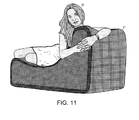
- FIG. 11 is a perspective view of an occupant resting on one of the chaise lounges of FIG. 9 .
- FIG. 12 is a perspective view of a foam seating article shaped as a chaise lounge as in FIG. 9 except that the inner shell is made from planar sheets of hard plastic instead of by blow molding.
- FIG. 13 is a cross-sectional view of the foam seating article of FIG. 12 .
- FIG. 14A is a perspective view of a foam seating article in the form of an Ottoman with an inner shell that is open at the bottom.
- FIG. 14B is a cross-sectional view of the foam seating article of FIG. 14A .
- FIG. 15A is a perspective view of a foam seating article in which a hard plastic bottom disk and an upper memory foam disk have been added to the seating article of FIGS. 14A-B .
- FIG. 15B is a cross-sectional view of the foam seating article of FIG. 15A .
- FIG. 16 is a bottom perspective view of a cylindrical foam seating article with an unzipped bottom circular flap of a fabric covering.
- FIG. 17A is a perspective view of a foam seating article similar to that of FIG. 15 except that the top plug is removable and allows access to the hollow shell.
- FIG. 17B is a cross-sectional view of the foam seating article of FIG. 17A .
- FIG. 18A is a perspective view of a foam seating article similar to that of FIGS. 17A-B except that the horizontal cross section of the outside of the molded foam layer is pentagonal instead of circular.
- FIG. 18B is a cross-sectional view of the foam seating article of FIG. 18A .
- FIG. 19 is a perspective view of four modular blocks of the foam seating article of FIGS. 18A-B .
- FIG. 20 is a flowchart of steps of a method of manufacturing the foam seating articles of the previous figures.
- FIG. 1 shows a foam seating article 10 in the form of a chair that is sized and configured to allow a single person to use the chair at one time. But other configurations of chair 10 could be sized and configured to allow two or more persons to sit on the chair at the same time.
- Chair 10 has a thick layer of molded memory foam surrounding a hollow shell of hard plastic. Thus, much of the inner volume of chair 10 is air. The hollow shell is made airtight in order to increase the rigidity of the hard plastic shell.
- a shell of polypropylene can provide sufficient support with a thickness of only three millimeters if the hollow shell is completely enclosed.
- the major weight component of chair 10 is the layer of molded memory foam that surrounds the hollow shell. Nevertheless, chair 10 still weighs much less than an equivalently sized chair with an inner wood or metal frame.
- FIG. 1 shows an occupant 11 comfortably seated in foam seating article 10 .
- a woven fabric covering 12 surrounds the memory foam.
- chair 10 has a covering made of nonwoven fabric, leather or even a conformal plastic layer.
- FIG. 2 shows the hollow shell 13 of hard plastic around which the thick layer of memory foam is molded to form chair 10 .
- Shell 13 is formed by blow molding a thermoplastic resin into a first mold.
- the thermoplastic resin is first extruded in the form of a tube or sheet, which is then expanded by blowing air into the tube inside a blow mold.
- the thermoplastic resin can be polypropylene (PP) resin, polyethylene (PE) resin, acrylonitrile butadiene styrene (ABS) resin, polyvinyl chloride (PVC) resin, polyvinyl acetate (PVA) resin, polycarbonate resin, polyamide resin, a polyphenylene oxide resin or a blend of these resins.
- shell 13 is made from a tube of 3-millimeter thick plasticized polypropylene (PP) resin.
- PP polypropylene
- the tube is placed inside the first mold and then sealed at both ends. The two halves of the first mold are then closed. Air is blown into the tube such that the blown up tube takes the shape of the interior of the first mold.
- air can be blown into the tube through an injection needle that punctures the tube.
- the needle passes through both the first mold and the tube of resin.
- the first mold includes small escape holes that allow the air trapped between the walls of the mold cavity and the resin tube to escape as the tube is filled with air and expands outwards to the walls of the mold.
- the sealed resin tube entirely covers the inside walls of the first mold.
- the resin tube is then cured and hardens when it is heated.
- the two halves of the first mold are then opened, and the cured resin tube is removed from the mold.
- the cured resin tube forms shell 13 .
- the tiny hole made by the injection needle is glued closed such that the shell 13 is air tight.
- the air pressure inside shell 13 provides added strength and helps to prevent the shell from collapsing inwards under the weight of occupant 11 .
- Foam is later molded around the outer surface of shell 13 .
- shell 13 is made of polypropylene surrounded by visco-elastic polyurethane foam (memory foam)
- the foam naturally sticks to the surface of the shell.
- it is advantageous to generate additional adhesion between the shell and the foam by forming an uneven outer surface on the shell to which the foam can better attach.
- dimples, grooves or crevices can be formed on the outside surface of shell 13 by providing micro-bumps or ribs on the inside surface of the first mold. The molded foam then sets up inside the dimples, grooves and crevices and becomes even more attached to shell 13 .
- FIG. 2 shows rows of dimples 14 that have been formed in the outer surface of shell 13 .
- FIG. 3 illustrates how foam is molded around shell 13 by placing the shell inside a second mold 15 .
- Second mold 15 has multiple sections, such as the top half 16 and bottom half 17 shown in FIG. 3 . In other embodiments, the second mold has a right half and a left half, or the second mold has more than two sections.
- a foam precursor mixture is then injected into the space 18 between shell 13 and the inner mold walls.
- two kinds of foam are molded around shell 13 .
- First, “high density” (HD) polyurethane foam is poured into space 18 in second mold 15 until about the bottom half of the mold cavity is filled.
- Second, visco-elastic memory foam is then poured into the remaining space between shell 13 and the inner mold walls. Latex can be used instead of memory foam in the remaining space.
- the molded foam is then allowed to set, and the second mold 15 is removed.
- HD high density
- an extra hard foam can be added first such that the bottom several inches of chair 10 have a more durable base.
- the indentation load deflection (ILD) is one measure of foam hardness.
- the extra hard bottom foam layer can have an ILD of about twenty, while the HD foam has an ILD of fifteen, and the memory foam has an ILD of twelve.
- the “high density” HD foam is somewhat of a misnomer because the memory foam has a higher density than does the HD foam. Density and hardness are not synonymous. Generally, denser foam is more durable.
- the HD foam used for cushioning has a density of between 1.5 to 2.5 pounds per cubic foot, whereas memory foam typically has a density between three and 5.5 pounds per cubic foot. Memory foam is temperature sensitive.
- At room temperature memory foam is harder than at skin temperature. Memory foam softens on contact and molds itself to the shape of a warm body within a few minutes. As occupant 11 sits on the memory foam that covers the top of chair 10 , the foam becomes softer, more pliant and more elastic.
- FIG. 4 shows foam seating article 10 after being removed from second mold 15 and before fabric covering 12 has been added.
- a layer of molded foam 19 surrounds hollow shell 13 .
- the thickness of molded foam layer 19 is about equal around shell 13 except on the bottom, where layer 19 is thinner.
- FIG. 5 is a cross-sectional view of chair 10 showing the thickness of molded foam layer 19 .
- Layer 19 includes a hard foam base portion 20 , an HD foam bottom portion 21 and a memory foam top portion 22 .
- the precursors of the different types of foam are poured into second mold 15 in a liquid state and cure together. Thus, no adhesive is required to bind the three foam portions together. Molded foam layer 19 naturally sticks to hard plastic shell 13 . However, the molded foam that flows into the dimples 14 in the outside surface of shell 13 provides additional bonding of layer 19 to shell 13 .
- FIGS. 6-7 show another embodiment of foam seating article 10 in which hollow shell 13 is cylindrical, and the thickness of molded foam layer 19 is not equal around shell 13 .
- Second portion 23 is not hollow. Instead, second portion 23 is shaped as a curved sitting surface suspended above the cylindrical hollow shell 13 . Hard plastic portion 23 is held in place within second mold 15 while the foam sets up around it. Neither shell 13 nor portion 23 is blow molded. Portion 23 can be injection molded.
- Shell 13 is a tube 24 that is capped at both ends by plugs 25 - 26 .
- Tube 24 is extruded polyvinyl chloride (PVC), polyvinyl acetate (PVA), polypropylene, polyethylene or a thermoplastic elastomer (TPE).
- PVC polyvinyl chloride
- PVA polyvinyl acetate
- TPE thermoplastic elastomer
- the plugs 25 - 26 are shaped as lipped disks that are glued over the ends of tube 24 forming an airtight seal.
- FIG. 8 shows an exploded view of foam seating article 10 of FIG. 6-7 .
- a top portion 27 of molded foam layer 19 is shown surrounding second portion 23 of hard plastic.
- a bottom portion 28 of molded foam layer 19 is shown surrounding cylindrical hollow shell 13 .
- FIG. 9 shows two modular foam seating articles 30 - 31 shaped as chaise lounges.
- the modular articles 30 - 31 can be placed together to form larger pieces of furniture, such as a sofa.
- Foam seating articles 30 - 31 are made in the same way as foam seating article 10 of FIG. 1 except that the inner hollow shell has a different shape.
- FIG. 10 shows an inner hollow shell 32 of hard plastic used to make foam seating article 31 of FIG. 9 .
- Shell 32 is formed in the same way as shell 13 is formed by blow molding a thermoplastic resin into a first mold. A layer of foam is then molded around shell 32 using a second mold. A woven fabric covering 33 is then placed around the molded foam.
- FIG. 11 shows an occupant 33 resting on chaise lounge 31 .
- FIG. 12 is a perspective view of a foam seating article 34 with a shape similar to that of chaise lounge 31 .
- the inner hollow shell 35 of article 34 is not made using blow molding.
- Shell 35 is constructed from sheets of hard plastic that have been cut to form the planar sides of shell 35 .
- the plastic sheets can be made of polypropylene, polyethylene, polyvinyl chloride (PVC), polyvinyl acetate (PVA) or a thermoplastic elastomer (TPE).
- the sides of shell 35 can be glued or melted together.
- Shell 35 has two portions, a bottom portion 36 and a back portion 37 . Each portion 36 - 37 is made airtight, and the two portions are then glued together. For example, the air pressure in airtight bottom portion 36 helps to prevent the flat top from sagging under the weight of the occupant of chaise lounge 34 .
- FIG. 13 is a cross-sectional view of foam seating article 34 of FIG. 12 .
- FIG. 13 shows that the layer of molded foam that surrounds hollow shell 35 is much thicker above bottom portion 36 of shell 35 than to the sides of shell 35 .
- FIGS. 14A-B show perspective and cross-sectional views of a foam seating article 38 in the form of an Ottoman, which can be used as a stool or a foot stool.
- Ottoman 38 has an inner hard plastic shell 39 that is open at the bottom.
- Shell 39 is a cylinder with one end closed.
- Shell 39 is formed as a single piece using injection molding instead of as an extruded tube with a planar, circular plug added separately as in the embodiment of FIG. 7 .
- Foam 40 is then molded around shell 39 leaving the bottom end 41 of the cylindrical shell open.
- a fabric covering (not shown) is then placed around the molded foam 40 and shell 39 . The covering covers the entire Ottoman 38 , including the open bottom end 41 of shell 39 .
- FIGS. 15A-B show a foam seating article 42 in which a hard plastic bottom disk 43 and an upper memory foam disk 44 have been added to Ottoman 38 of FIG. 14 .
- Hard plastic bottom disk 43 is glued over the bottom end 41 of shell 39 .
- Disk 44 of memory foam is glued to the top of molded foam 40 .
- a removable fabric covering 45 is then placed around foam disk 44 , molded foam 40 and hard plastic bottom disk 43 .
- the bottom circle of fabric covering 45 can be opened with a zipper to remove the covering 45 from the foam.
- FIG. 16 is a bottom perspective view of foam seating article 42 with the bottom circular flap of covering 45 unzipped.
- a zipper 46 is sewn around the circumference of the bottom flap. When the flap is unzipped, fabric covering 45 can be slid off from the cylindrical Ottoman 42 .
- FIGS. 17A-B show perspective and cross-sectional views of a foam seating article 47 similar to Ottoman 42 of FIG. 15 .
- Article 47 can be used for storage, however, because the top plug 48 is removable.
- article 47 can be used as a foot stool for a sofa, as well as a storage bin for children's toys.
- the shell of article 47 is a tube 49 that is capped at both ends by lipped disks 50 - 51 .
- Tube 49 is a portion of an extruded polyvinyl chloride (PVC) pipe, and lipped disks 50 - 51 fit into the ends of tube 49 .
- Lower disk 50 is glued to the bottom end of tube 49 .
- a layer of molded foam 40 is molded around the sides of tube 49 .
- Top plug 48 includes upper disk 51 to which a disk of memory foam 44 is glued. An upper portion 52 of the covering 45 fits around the top of memory foam disk 44 . Upper disk 51 , memory foam disk 44 and upper portion 52 of the covering 45 together form the top plug 48 and can be removed from article 47 as a unit to gain access to the cavity inside tube 49 . A lower portion 53 of the covering 45 fits around molded foam 40 and lower disk 50 .
- FIGS. 18A-B show perspective and cross-sectional views of a foam seating article 54 similar to seating article 47 of FIG. 17 except for the shape of the molded foam layer 40 .
- the horizontal cross section of the inner, hard-plastic shell is circular, whereas the horizontal cross section of the outside of molded foam layer 40 is pentagonal.
- Article 54 has a pentagonal top lid made up of upper disk 51 , memory foam 44 and a fabric covering (not shown).
- Upper disk 51 has a circular bottom and a pentagonal upper lip.
- FIG. 19 shows four modular blocks of the foam seating article 54 .
- the blocks 54 of FIG. 19 can also be used in a children's room as stools that store toys.
- FIG. 20 is a flowchart illustrating steps 55 - 58 of a method of manufacturing the foam seating articles described above. Molding foam around a hard plastic shell is a simpler and less costly manufacturing process than shaping metal and wood to make a frame and then adding springs, padding and upholstery. And it is easier to make curved shapes by molding the inner shell and outer foam than it is to make a curved inner frame from wood or metal. In addition, the foam and plastic construction does not include nails that can come loose with extended use.
- hollow shell 13 is formed using blow molding, injection molding or by attaching disks to both ends of a tube.
- blow molding is used to make hollow shell 13
- a tube of plasticized resin is placed inside a first mold and then sealed at both ends.
- the first mold is closed, and air is blown into the tube of resin such that the resin sheet expands outwards towards the walls of the mold and takes the shape of the interior of the mold.
- the shell is given an uneven outer surface with dimples or grooves by providing micro-bumps or ribs on the inside surface of the first mold.
- the resin tube is then cured.
- the first mold is opened, and the cured resin shell 13 is removed from the mold.
- step 56 the hollow shell 13 is placed in second mold 15 .
- Shell 13 must be supported inside second mold 15 so that the shell does not sit at the bottom of the mold and so that there is spacing between shell 13 and all of the inside walls of second mold 15 .
- step 57 foam is molded around the outer surface of hollow shell 13 .
- Liquid foam precursors are injected into the space between shell 13 and the inner walls of second mold 15 .
- Different kinds of foams can be successively poured into second mold 15 .
- the precursors of an extra hard foam with an ILD of about twenty are first added to fill the bottom several inches of space 18 in second mold 15 .
- the precursors of HD polyurethane foam with an ILD of about fifteen are added until about the bottom half of space 18 is filled.
- memory foam is poured into the remaining space 18 between shell 13 and the inner mold walls.
- the memory foam has an ILD of about twelve.
- the liquid foam precursors of the molded foam layer 19 are cured, and the foam with shell are removed from the second mold 15 .
- covering 12 is then placed around molded foam layer 19 and hollow shell 13 .
- Covering 12 is made of woven fabric, nonwoven fabric, leather or a conformal plastic or rubber layer.
- foam seating article 54 of FIG. 19 can be given a conformal rubber covering by dipping the foam layer 40 and shell into a synthetic rubber bath.
Landscapes
- Engineering & Computer Science (AREA)
- Mechanical Engineering (AREA)
- Manufacturing & Machinery (AREA)
- Casting Or Compression Moulding Of Plastics Or The Like (AREA)
- Mattresses And Other Support Structures For Chairs And Beds (AREA)
- Chair Legs, Seat Parts, And Backrests (AREA)
- Injection Moulding Of Plastics Or The Like (AREA)
Abstract
Description
Claims (15)
Priority Applications (9)
| Application Number | Priority Date | Filing Date | Title |
|---|---|---|---|
| US14/093,222 US9420890B2 (en) | 2013-11-29 | 2013-11-29 | Foam furniture molded around a hollow shell of hard plastic |
| KR20140013517A KR101500621B1 (en) | 2013-11-29 | 2014-02-06 | Foam furniture molded around a hollow shelll of hard plastic |
| US14/259,156 US9420891B2 (en) | 2013-11-29 | 2014-04-23 | Foam furniture molded around a rigid foam core |
| KR20140061223A KR101500622B1 (en) | 2013-11-29 | 2014-05-21 | Foam furniture molded around a rigid foam core |
| US14/511,471 US9456696B2 (en) | 2013-11-29 | 2014-10-10 | Foam furniture molded around a core with a lumbar support protrusion |
| KR1020140160339A KR20150062947A (en) | 2013-11-29 | 2014-11-17 | Foam furniture molded around a rigid foam core |
| US15/224,459 US20160331141A1 (en) | 2013-11-29 | 2016-07-29 | Foam Furniture Molded Around a Rigid Foam Core |
| US15/224,667 US10271657B2 (en) | 2013-11-29 | 2016-08-01 | Foam furniture molded around a hollow shell of hard plastic |
| US15/253,770 US20160367032A1 (en) | 2013-11-29 | 2016-08-31 | Foam Furniture Molded Around a Core with a Lumbar Support Protrusion |
Applications Claiming Priority (1)
| Application Number | Priority Date | Filing Date | Title |
|---|---|---|---|
| US14/093,222 US9420890B2 (en) | 2013-11-29 | 2013-11-29 | Foam furniture molded around a hollow shell of hard plastic |
Related Child Applications (2)
| Application Number | Title | Priority Date | Filing Date |
|---|---|---|---|
| US14/259,156 Continuation-In-Part US9420891B2 (en) | 2013-11-29 | 2014-04-23 | Foam furniture molded around a rigid foam core |
| US15/224,667 Continuation US10271657B2 (en) | 2013-11-29 | 2016-08-01 | Foam furniture molded around a hollow shell of hard plastic |
Publications (2)
| Publication Number | Publication Date |
|---|---|
| US20150150378A1 US20150150378A1 (en) | 2015-06-04 |
| US9420890B2 true US9420890B2 (en) | 2016-08-23 |
Family
ID=53026938
Family Applications (2)
| Application Number | Title | Priority Date | Filing Date |
|---|---|---|---|
| US14/093,222 Expired - Fee Related US9420890B2 (en) | 2013-11-29 | 2013-11-29 | Foam furniture molded around a hollow shell of hard plastic |
| US15/224,667 Expired - Fee Related US10271657B2 (en) | 2013-11-29 | 2016-08-01 | Foam furniture molded around a hollow shell of hard plastic |
Family Applications After (1)
| Application Number | Title | Priority Date | Filing Date |
|---|---|---|---|
| US15/224,667 Expired - Fee Related US10271657B2 (en) | 2013-11-29 | 2016-08-01 | Foam furniture molded around a hollow shell of hard plastic |
Country Status (2)
| Country | Link |
|---|---|
| US (2) | US9420890B2 (en) |
| KR (1) | KR101500621B1 (en) |
Cited By (6)
| Publication number | Priority date | Publication date | Assignee | Title |
|---|---|---|---|---|
| US10206514B1 (en) * | 2016-12-06 | 2019-02-19 | Keith Lawrence Zivalich | Contoured meditation seat |
| US20200046131A1 (en) * | 2016-10-13 | 2020-02-13 | Humantool Oy | Seat base for a saddle seat |
| US10588414B2 (en) | 2018-06-08 | 2020-03-17 | Series International, Llc | Chair frame with injection molded foam padding |
| USD953766S1 (en) | 2018-11-01 | 2022-06-07 | Inharmony Interactive | Seating apparatus |
| US11751694B2 (en) | 2020-09-29 | 2023-09-12 | Craftsman Upholstery & Interiors, Llc | Method and apparatus for creating a kneeler pad using a thermoforming process |
| US12408756B1 (en) | 2022-05-27 | 2025-09-09 | Series International, Llc | Stacking chair with removable back |
Families Citing this family (17)
| Publication number | Priority date | Publication date | Assignee | Title |
|---|---|---|---|---|
| WO2018203222A1 (en) * | 2017-05-01 | 2018-11-08 | North Carolina State University | A molded nonwoven assembly and a method for manufacturing a molded nonwoven assembly |
| USD845016S1 (en) * | 2017-11-03 | 2019-04-09 | Idea Nuova, Inc. | Couch chair |
| US11033778B2 (en) * | 2018-06-13 | 2021-06-15 | Julie Ann Wattenberg | Fitness device for exercise and balance development |
| USD927880S1 (en) | 2019-07-28 | 2021-08-17 | Comfort Research, Llc | Chair |
| KR102502712B1 (en) * | 2019-09-06 | 2023-02-23 | (주)에이앤씨인터내셔널 | Seat board for a chair and manufacturing method thereof |
| USD906715S1 (en) * | 2019-10-12 | 2021-01-05 | Dongguan City Baby Furniture Co., Ltd | Sofa for children |
| USD927214S1 (en) | 2019-11-21 | 2021-08-10 | Comfort Research, Llc | Chair |
| USD927881S1 (en) | 2019-11-21 | 2021-08-17 | Comfort Research, Llc | Chair |
| USD927213S1 (en) | 2019-11-21 | 2021-08-10 | Comfort Research, Llc | Chair |
| USD927215S1 (en) | 2019-11-21 | 2021-08-10 | Comfort Research, Llc | Chair |
| TR201918531A1 (en) * | 2019-11-26 | 2021-06-21 | Taskiranlar Hali Pazarlama Mob Ins San Ve Tic A S | Furniture assembly in where textile is fixed to soft material and the soft material is fixed with plastic, wood or cardboard body/skeleton and the production method of it |
| USD954459S1 (en) * | 2020-12-29 | 2022-06-14 | CPA Advisory Trust | Gaming chair bean bag |
| USD1029517S1 (en) * | 2021-12-13 | 2024-06-04 | Hangzhou Shinnwa Hometex Co., Ltd. | Chair |
| USD1052918S1 (en) * | 2023-01-20 | 2024-12-03 | Rick Dieterle | Chair with support and beanbag cushion |
| USD1052919S1 (en) * | 2023-03-07 | 2024-12-03 | Clifton Wilcox | Ring chair |
| USD1072510S1 (en) * | 2024-01-12 | 2025-04-29 | Jun He | Inflatable sofa |
| USD1077502S1 (en) * | 2025-01-23 | 2025-06-03 | Ningbo Yousun Imp.and Exp. Co., Ltd | Sofa |
Citations (39)
| Publication number | Priority date | Publication date | Assignee | Title |
|---|---|---|---|---|
| US3325214A (en) * | 1966-07-25 | 1967-06-13 | Goodrich Co B F | Headrest |
| US3543315A (en) * | 1967-10-09 | 1970-12-01 | William L Hoffman | Soft board fabrication |
| US3556586A (en) * | 1968-02-16 | 1971-01-19 | Karoll S Inc | Multipurpose furniture |
| US3620570A (en) * | 1969-10-08 | 1971-11-16 | Jean B Wilson | Chair-boat structure |
| US3719185A (en) * | 1970-11-30 | 1973-03-06 | C Hanes | Orthopedic bolster pillow |
| US3761130A (en) * | 1971-05-19 | 1973-09-25 | Tenryu Industries | Convertible chair |
| US4118813A (en) * | 1976-11-10 | 1978-10-10 | Armstrong Nolen L | Sleep training pillow for the prevention of snoring |
| US4258952A (en) * | 1978-12-15 | 1981-03-31 | Dutra Antonio S | Rocking couch, chaise, lounge, recliner, chair or relaxer |
| EP0179043A1 (en) | 1984-10-16 | 1986-04-23 | "Velda", naamloze vennootschap | Method for manufacturing furniture from foam, products obtained thereby, and mould used therewith |
| US4858994A (en) * | 1987-09-30 | 1989-08-22 | Ikeda Bussan Co., Ltd. | Adjustable headrest for automotive seat |
| US4902003A (en) * | 1985-09-23 | 1990-02-20 | Buoni Nick J | Exercise device and method |
| US4988090A (en) | 1989-03-23 | 1991-01-29 | Schmitt Marcella H | Portable, safety, play furniture assembly |
| JPH0595847A (en) * | 1991-10-11 | 1993-04-20 | Sekisui Chem Co Ltd | Chair |
| US5316372A (en) * | 1987-09-10 | 1994-05-31 | Ford Motor Company | Headrest for a motor vehicle |
| US5415461A (en) | 1993-10-29 | 1995-05-16 | Sakamoto; Alice | Furniture construction |
| US5744231A (en) | 1991-05-23 | 1998-04-28 | Sumitomo Chemical Company, Limited | Composite foam molded article, process for production thereof composition |
| US5778469A (en) * | 1997-05-13 | 1998-07-14 | Festa; John Philip | Therapeutic cervical pillow |
| US5801211A (en) | 1996-10-04 | 1998-09-01 | Cinco, Inc. | Resilient fiber mass and method |
| US5857742A (en) | 1994-03-14 | 1999-01-12 | Norix Group, Inc. | Molding chair |
| US5967612A (en) * | 1998-06-18 | 1999-10-19 | Tachi-S Co., Ltd. | Headrest for automotive seat |
| US6183045B1 (en) * | 1998-06-03 | 2001-02-06 | Magna Interior Systems Inc. | Method of manufacturing an interior automotive component and components made therefrom |
| US6360387B1 (en) * | 2000-10-16 | 2002-03-26 | Mirchana S. Everhart | Fertility pillow |
| US6457773B1 (en) * | 2001-08-31 | 2002-10-01 | Richard L. Gates | Transportable cushioning device |
| US20020151233A1 (en) * | 2000-07-28 | 2002-10-17 | Philippe Renard | Subassembly designed to produce an aquatic gliding board |
| US20030233694A1 (en) * | 2002-06-25 | 2003-12-25 | Michael Wescombe-Down | Protective swimsuit incorporating an electrical wiring system |
| US6702391B1 (en) | 1995-06-07 | 2004-03-09 | Grant Stipek | Furniture with molded frame |
| US6726284B2 (en) | 2000-01-18 | 2004-04-27 | Bobby D. Cleary | Furniture construction and method |
| US6877817B1 (en) * | 2003-10-02 | 2005-04-12 | Nancy L. Brown | Stool with leg supports |
| US6997513B2 (en) * | 2003-08-13 | 2006-02-14 | Salubrion Llc | Chair for healthy sitting |
| US20060145526A1 (en) | 2002-10-17 | 2006-07-06 | Niekel Edwin J | Light weight seating furniture construction with so-called memory effect |
| US7108646B1 (en) * | 2002-11-12 | 2006-09-19 | Quick Catherine G | Infant roll cushion and method |
| US20070283865A1 (en) * | 2004-11-01 | 2007-12-13 | Bouncing Brain Innovations Season Two Subsidiary 14, Llc | Powered surfboard for preserving energy of surfer during paddling |
| US20080292830A1 (en) | 2007-05-21 | 2008-11-27 | Featherlyte, Llc | Multi-layered foam furniture method and apparatus |
| US7571965B1 (en) | 2007-08-16 | 2009-08-11 | Perry Michael L | Molded foam pool chair |
| US20110094033A1 (en) * | 2009-10-28 | 2011-04-28 | Zinus Inc. | Anti-snore neck-support contour pillow |
| US7998031B2 (en) * | 2006-09-28 | 2011-08-16 | Sharon Dumke | Exercise device for aquatic use |
| US20130062922A1 (en) * | 2011-09-12 | 2013-03-14 | Christopher S. Dickson | Leg Elevation Device |
| US20130104787A1 (en) * | 2009-07-01 | 2013-05-02 | Kendyl A. Roman | Clean Energy Powered Surfboards |
| US8496860B2 (en) | 2009-07-31 | 2013-07-30 | Fusion Specialties, Inc. | Foam-backed, hollow articles made by cold rotational molding |
Family Cites Families (28)
| Publication number | Priority date | Publication date | Assignee | Title |
|---|---|---|---|---|
| US2880428A (en) | 1957-02-27 | 1959-04-07 | Audre C Forsland | Posture pillow |
| US3161436A (en) | 1962-03-27 | 1964-12-15 | Davidson Rubber Company Inc | Pre-stressed molded foam cushioning element |
| US3842453A (en) | 1972-08-15 | 1974-10-22 | N Redfield | Posture pillow |
| EP0044083A1 (en) | 1980-07-14 | 1982-01-20 | Alkor GmbH Kunststoffe | Method of producing foam-padded deep-drawn plastic articles |
| US4471993A (en) | 1981-11-13 | 1984-09-18 | Watson Steven R | Personalized low back support device |
| JPS58185235A (en) | 1982-04-23 | 1983-10-28 | Toyo Rubber Chem Ind Co Ltd | Manufacture of cushion and its mold |
| BE1002899A6 (en) | 1989-03-03 | 1991-07-16 | Recticel | METHOD FOR MANUFACTURING ARTICLES WITH ELASTOMERIC EXTERIOR WALL AND PLASTIC FOAM CORE |
| CN2081676U (en) | 1991-02-07 | 1991-07-31 | 梁瑞杰 | Soft sofa |
| US5240528A (en) | 1991-05-31 | 1993-08-31 | Pagni Larry P | Foamed core furniture structure and method of making same |
| US5474362A (en) | 1991-06-26 | 1995-12-12 | Albecker, Iii; Walter J. | Cushions having internal support member |
| US6022205A (en) | 1998-07-06 | 2000-02-08 | Tas Enterprise, L.L.C. | System for producing and conditioning blocks of flexible polyurethane foam |
| CN1273979A (en) | 1999-05-17 | 2000-11-22 | 珠海市江奇家具有限公司 | Furniture core material made of polyurethane and its production method |
| US6684433B2 (en) | 2001-03-07 | 2004-02-03 | Gualtiero G. Giori | Pressure adjustable foam support apparatus |
| US20020167136A1 (en) | 2001-03-09 | 2002-11-14 | Lehr Gregory S. | Dual density foam core sports board |
| CA2404609A1 (en) | 2001-09-21 | 2003-03-21 | The Upholstery Studio, Inc. | Furniture backing support |
| US20040026970A1 (en) | 2002-05-28 | 2004-02-12 | Vassar Matthew William | Upholstered furniture inserts |
| US7201625B2 (en) | 2004-03-11 | 2007-04-10 | Tzong In Yeh | Foam product having outer skin and method for producing the same |
| JP3110643U (en) * | 2005-02-24 | 2005-06-30 | 榮子 山本 | Portable chair and bag |
| US7922944B2 (en) | 2005-10-03 | 2011-04-12 | L&P Property Management Company | Blow mold and backfill manufacturing process |
| KR20110088576A (en) * | 2006-06-09 | 2011-08-03 | 삭 액큐지션 엘엘씨 | Modular furniture assemblies |
| KR20100139007A (en) | 2008-03-10 | 2010-12-31 | 바스프 에스이 | Molded composite articles, especially for furniture |
| US8141957B2 (en) | 2008-12-15 | 2012-03-27 | La-Z-Boy Incorporated | Cushion with plural zones of foam |
| WO2010075231A1 (en) * | 2008-12-22 | 2010-07-01 | Tempur-Pedic Management, Inc. | Thin-layered alternating material body support and method of manufacturing same |
| WO2011084804A2 (en) | 2009-12-21 | 2011-07-14 | Saint-Gobain Performance Plastics Corporation | Thermally conductive foam material |
| US8398166B2 (en) | 2010-03-11 | 2013-03-19 | Honda Motor Co., Ltd. | Vehicle seat assembly |
| PL2569186T3 (en) * | 2010-05-12 | 2015-10-30 | Johnson Controls Tech Co | Flexible interior trim component having an integral skin show surface |
| EP2576175A1 (en) | 2010-05-27 | 2013-04-10 | Dow Global Technologies LLC | Method of manufacturing a shaped foam article |
| FR2996809B1 (en) | 2012-10-15 | 2014-12-19 | Cera | HEADREST FOR THE SEAT OF A MOTOR VEHICLE |
-
2013
- 2013-11-29 US US14/093,222 patent/US9420890B2/en not_active Expired - Fee Related
-
2014
- 2014-02-06 KR KR20140013517A patent/KR101500621B1/en not_active Expired - Fee Related
-
2016
- 2016-08-01 US US15/224,667 patent/US10271657B2/en not_active Expired - Fee Related
Patent Citations (39)
| Publication number | Priority date | Publication date | Assignee | Title |
|---|---|---|---|---|
| US3325214A (en) * | 1966-07-25 | 1967-06-13 | Goodrich Co B F | Headrest |
| US3543315A (en) * | 1967-10-09 | 1970-12-01 | William L Hoffman | Soft board fabrication |
| US3556586A (en) * | 1968-02-16 | 1971-01-19 | Karoll S Inc | Multipurpose furniture |
| US3620570A (en) * | 1969-10-08 | 1971-11-16 | Jean B Wilson | Chair-boat structure |
| US3719185A (en) * | 1970-11-30 | 1973-03-06 | C Hanes | Orthopedic bolster pillow |
| US3761130A (en) * | 1971-05-19 | 1973-09-25 | Tenryu Industries | Convertible chair |
| US4118813A (en) * | 1976-11-10 | 1978-10-10 | Armstrong Nolen L | Sleep training pillow for the prevention of snoring |
| US4258952A (en) * | 1978-12-15 | 1981-03-31 | Dutra Antonio S | Rocking couch, chaise, lounge, recliner, chair or relaxer |
| EP0179043A1 (en) | 1984-10-16 | 1986-04-23 | "Velda", naamloze vennootschap | Method for manufacturing furniture from foam, products obtained thereby, and mould used therewith |
| US4902003A (en) * | 1985-09-23 | 1990-02-20 | Buoni Nick J | Exercise device and method |
| US5316372A (en) * | 1987-09-10 | 1994-05-31 | Ford Motor Company | Headrest for a motor vehicle |
| US4858994A (en) * | 1987-09-30 | 1989-08-22 | Ikeda Bussan Co., Ltd. | Adjustable headrest for automotive seat |
| US4988090A (en) | 1989-03-23 | 1991-01-29 | Schmitt Marcella H | Portable, safety, play furniture assembly |
| US5744231A (en) | 1991-05-23 | 1998-04-28 | Sumitomo Chemical Company, Limited | Composite foam molded article, process for production thereof composition |
| JPH0595847A (en) * | 1991-10-11 | 1993-04-20 | Sekisui Chem Co Ltd | Chair |
| US5415461A (en) | 1993-10-29 | 1995-05-16 | Sakamoto; Alice | Furniture construction |
| US5857742A (en) | 1994-03-14 | 1999-01-12 | Norix Group, Inc. | Molding chair |
| US6702391B1 (en) | 1995-06-07 | 2004-03-09 | Grant Stipek | Furniture with molded frame |
| US5801211A (en) | 1996-10-04 | 1998-09-01 | Cinco, Inc. | Resilient fiber mass and method |
| US5778469A (en) * | 1997-05-13 | 1998-07-14 | Festa; John Philip | Therapeutic cervical pillow |
| US6183045B1 (en) * | 1998-06-03 | 2001-02-06 | Magna Interior Systems Inc. | Method of manufacturing an interior automotive component and components made therefrom |
| US5967612A (en) * | 1998-06-18 | 1999-10-19 | Tachi-S Co., Ltd. | Headrest for automotive seat |
| US6726284B2 (en) | 2000-01-18 | 2004-04-27 | Bobby D. Cleary | Furniture construction and method |
| US20020151233A1 (en) * | 2000-07-28 | 2002-10-17 | Philippe Renard | Subassembly designed to produce an aquatic gliding board |
| US6360387B1 (en) * | 2000-10-16 | 2002-03-26 | Mirchana S. Everhart | Fertility pillow |
| US6457773B1 (en) * | 2001-08-31 | 2002-10-01 | Richard L. Gates | Transportable cushioning device |
| US20030233694A1 (en) * | 2002-06-25 | 2003-12-25 | Michael Wescombe-Down | Protective swimsuit incorporating an electrical wiring system |
| US20060145526A1 (en) | 2002-10-17 | 2006-07-06 | Niekel Edwin J | Light weight seating furniture construction with so-called memory effect |
| US7108646B1 (en) * | 2002-11-12 | 2006-09-19 | Quick Catherine G | Infant roll cushion and method |
| US6997513B2 (en) * | 2003-08-13 | 2006-02-14 | Salubrion Llc | Chair for healthy sitting |
| US6877817B1 (en) * | 2003-10-02 | 2005-04-12 | Nancy L. Brown | Stool with leg supports |
| US20070283865A1 (en) * | 2004-11-01 | 2007-12-13 | Bouncing Brain Innovations Season Two Subsidiary 14, Llc | Powered surfboard for preserving energy of surfer during paddling |
| US7998031B2 (en) * | 2006-09-28 | 2011-08-16 | Sharon Dumke | Exercise device for aquatic use |
| US20080292830A1 (en) | 2007-05-21 | 2008-11-27 | Featherlyte, Llc | Multi-layered foam furniture method and apparatus |
| US7571965B1 (en) | 2007-08-16 | 2009-08-11 | Perry Michael L | Molded foam pool chair |
| US20130104787A1 (en) * | 2009-07-01 | 2013-05-02 | Kendyl A. Roman | Clean Energy Powered Surfboards |
| US8496860B2 (en) | 2009-07-31 | 2013-07-30 | Fusion Specialties, Inc. | Foam-backed, hollow articles made by cold rotational molding |
| US20110094033A1 (en) * | 2009-10-28 | 2011-04-28 | Zinus Inc. | Anti-snore neck-support contour pillow |
| US20130062922A1 (en) * | 2011-09-12 | 2013-03-14 | Christopher S. Dickson | Leg Elevation Device |
Cited By (9)
| Publication number | Priority date | Publication date | Assignee | Title |
|---|---|---|---|---|
| US20200046131A1 (en) * | 2016-10-13 | 2020-02-13 | Humantool Oy | Seat base for a saddle seat |
| US11033108B2 (en) * | 2016-10-13 | 2021-06-15 | Humantool Oy | Seat base for a saddle seat |
| US10206514B1 (en) * | 2016-12-06 | 2019-02-19 | Keith Lawrence Zivalich | Contoured meditation seat |
| US10588414B2 (en) | 2018-06-08 | 2020-03-17 | Series International, Llc | Chair frame with injection molded foam padding |
| US10835045B2 (en) | 2018-06-08 | 2020-11-17 | Series International, Llc | Chair frame with injection molded foam padding |
| US11457744B2 (en) | 2018-06-08 | 2022-10-04 | Series International, Llc | Chair frame with injection molded foam padding |
| USD953766S1 (en) | 2018-11-01 | 2022-06-07 | Inharmony Interactive | Seating apparatus |
| US11751694B2 (en) | 2020-09-29 | 2023-09-12 | Craftsman Upholstery & Interiors, Llc | Method and apparatus for creating a kneeler pad using a thermoforming process |
| US12408756B1 (en) | 2022-05-27 | 2025-09-09 | Series International, Llc | Stacking chair with removable back |
Also Published As
| Publication number | Publication date |
|---|---|
| US20160338493A1 (en) | 2016-11-24 |
| KR101500621B1 (en) | 2015-03-18 |
| US10271657B2 (en) | 2019-04-30 |
| US20150150378A1 (en) | 2015-06-04 |
Similar Documents
| Publication | Publication Date | Title |
|---|---|---|
| US10271657B2 (en) | Foam furniture molded around a hollow shell of hard plastic | |
| US9420891B2 (en) | Foam furniture molded around a rigid foam core | |
| US9456696B2 (en) | Foam furniture molded around a core with a lumbar support protrusion | |
| US8434748B1 (en) | Cushions comprising gel springs | |
| US8932692B2 (en) | Cushions comprising deformable members and related methods | |
| US2838100A (en) | Chair, sofa, or similar article | |
| US8628067B2 (en) | Cushions comprising core structures and related methods | |
| US20130081209A1 (en) | Cellular mattress assemblies and related methods | |
| US20120060296A1 (en) | Foam mattress | |
| US20170245664A1 (en) | Dual density molded foam pillow | |
| US20140130265A1 (en) | All-foam mattress assemblies with foam engineered cores having thermoplastic and thermoset materials, and related assemblies and methods | |
| KR20120082401A (en) | Modular support element | |
| WO2015150920A2 (en) | Support cushions for providing ventilation | |
| US20190038043A1 (en) | Dual density systems and methods for bedding applications | |
| CN101431925A (en) | Chair | |
| KR102396668B1 (en) | Pillow with adjustable massing and height | |
| US3844613A (en) | Seating construction | |
| KR101040908B1 (en) | Latex Foam Molding Mold | |
| CN219125895U (en) | Composite sheet for home textile product and home textile product | |
| KR20190067358A (en) | Mattress combination sofa with air cushion | |
| US3797885A (en) | Seat type article of furniture and method of manufacturing | |
| RU2223022C1 (en) | Filler for piece of furniture or bedding | |
| KR20170083517A (en) | Seat board of chair | |
| RU187034U1 (en) | MATTRESS | |
| CN201388773Y (en) | rest cushion |
Legal Events
| Date | Code | Title | Description |
|---|---|---|---|
| AS | Assignment |
Owner name: ZINUS INC., CALIFORNIA Free format text: ASSIGNMENT OF ASSIGNORS INTEREST;ASSIGNOR:LEE, YOUN JAE;REEL/FRAME:031744/0704 Effective date: 20131128 |
|
| ZAAA | Notice of allowance and fees due |
Free format text: ORIGINAL CODE: NOA |
|
| ZAAB | Notice of allowance mailed |
Free format text: ORIGINAL CODE: MN/=. |
|
| STCF | Information on status: patent grant |
Free format text: PATENTED CASE |
|
| MAFP | Maintenance fee payment |
Free format text: PAYMENT OF MAINTENANCE FEE, 4TH YEAR, LARGE ENTITY (ORIGINAL EVENT CODE: M1551); ENTITY STATUS OF PATENT OWNER: LARGE ENTITY Year of fee payment: 4 |
|
| AS | Assignment |
Owner name: ZINUS, INC., CALIFORNIA Free format text: CORRECTIVE ASSIGNMENT TO CORRECT THE RECEIVING PARTY'S DATA ON THE COVER SHEET PREVIOUSLY RECORDED AT REEL: 031744 FRAME: 0704. ASSIGNOR(S) HEREBY CONFIRMS THE ASSIGNMENT;ASSIGNOR:LEE, YOUN JAE;REEL/FRAME:063888/0461 Effective date: 20131128 |
|
| FEPP | Fee payment procedure |
Free format text: MAINTENANCE FEE REMINDER MAILED (ORIGINAL EVENT CODE: REM.); ENTITY STATUS OF PATENT OWNER: LARGE ENTITY |
|
| LAPS | Lapse for failure to pay maintenance fees |
Free format text: PATENT EXPIRED FOR FAILURE TO PAY MAINTENANCE FEES (ORIGINAL EVENT CODE: EXP.); ENTITY STATUS OF PATENT OWNER: LARGE ENTITY |
|
| STCH | Information on status: patent discontinuation |
Free format text: PATENT EXPIRED DUE TO NONPAYMENT OF MAINTENANCE FEES UNDER 37 CFR 1.362 |
|
| FP | Lapsed due to failure to pay maintenance fee |
Effective date: 20240823 |