US9416640B2 - Downhole wellbore heating system and method - Google Patents
Downhole wellbore heating system and method Download PDFInfo
- Publication number
- US9416640B2 US9416640B2 US14/033,072 US201314033072A US9416640B2 US 9416640 B2 US9416640 B2 US 9416640B2 US 201314033072 A US201314033072 A US 201314033072A US 9416640 B2 US9416640 B2 US 9416640B2
- Authority
- US
- United States
- Prior art keywords
- cable
- support member
- cables
- heating
- heating cables
- Prior art date
- Legal status (The legal status is an assumption and is not a legal conclusion. Google has not performed a legal analysis and makes no representation as to the accuracy of the status listed.)
- Active, expires
Links
Images






Classifications
-
- E—FIXED CONSTRUCTIONS
- E21—EARTH OR ROCK DRILLING; MINING
- E21B—EARTH OR ROCK DRILLING; OBTAINING OIL, GAS, WATER, SOLUBLE OR MELTABLE MATERIALS OR A SLURRY OF MINERALS FROM WELLS
- E21B43/00—Methods or apparatus for obtaining oil, gas, water, soluble or meltable materials or a slurry of minerals from wells
- E21B43/16—Enhanced recovery methods for obtaining hydrocarbons
- E21B43/24—Enhanced recovery methods for obtaining hydrocarbons using heat, e.g. steam injection
- E21B43/2401—Enhanced recovery methods for obtaining hydrocarbons using heat, e.g. steam injection by means of electricity
-
- E—FIXED CONSTRUCTIONS
- E21—EARTH OR ROCK DRILLING; MINING
- E21B—EARTH OR ROCK DRILLING; OBTAINING OIL, GAS, WATER, SOLUBLE OR MELTABLE MATERIALS OR A SLURRY OF MINERALS FROM WELLS
- E21B17/00—Drilling rods or pipes; Flexible drill strings; Kellies; Drill collars; Sucker rods; Cables; Casings; Tubings
- E21B17/10—Wear protectors; Centralising devices, e.g. stabilisers
- E21B17/1042—Elastomer protector or centering means
- E21B17/105—Elastomer protector or centering means split type
-
- E—FIXED CONSTRUCTIONS
- E21—EARTH OR ROCK DRILLING; MINING
- E21B—EARTH OR ROCK DRILLING; OBTAINING OIL, GAS, WATER, SOLUBLE OR MELTABLE MATERIALS OR A SLURRY OF MINERALS FROM WELLS
- E21B33/00—Sealing or packing boreholes or wells
- E21B33/02—Surface sealing or packing
- E21B33/03—Well heads; Setting-up thereof
- E21B33/04—Casing heads; Suspending casings or tubings in well heads
- E21B33/0407—Casing heads; Suspending casings or tubings in well heads with a suspended electrical cable
Definitions
- heat can be delivered to the production tubing in the well via a heater installation in order to heat the oil to be extracted, reducing its viscosity and improving extraction rates.
- the heater installation can deliver heat to the oil reservoir itself to increase the amount of oil that enters the production tubing.
- Existing downhole heater installations typically require the use of a drilling or other rig.
- the installation of a heater is usually managed by clamping heater cables to the exterior of the production tubing, which generally requires that a complete workover or similar operation must be performed. Such operations can be very time consuming and expensive processes.
- heating systems of the present invention can be deployed within continuous tubing, frequently referred to as “coiled tubing” because it is sufficiently flexible to be coiled onto a spool and transported to the deployment site.
- Deployment of coiled tubing heaters improves heat transfer to a target medium because such coiled tubing heaters provide a larger surface area in contact with said medium, and can frequently be installed so as to be in direct contact with said medium.
- exposure of heater cables to well fluids can be problematic due to the chemical makeup of such fluids, installation of such heater cables within coiled tubing isolates and protects heater cables from such well fluids.
- such continuous tubing heating devices can be installed without performing a workover, or requiring the use of a drilling or other rig.
- Electric cables typically do not have sufficient tensile strength to be deployed independently within a tube, especially over relatively long vertical sections. Accordingly, various means of providing support to heater cables have been designed including, without limitation, for downhole skin-effect heaters like the skin-effect heating cable described in co-pending United States Patent Application Publication No. 2011/0233192, entitled “SKIN EFFECT HEATING SYSTEM HAVING IMPROVED HEAT TRANSFER AND WIRE SUPPORT CHARACTERISTICS”, which is incorporated herein by reference. Unfortunately, such existing methods are generally not suitable to use with multiple independent cables, such as mineral insulated (“MI”) cables, that comprise their own electrical circuit and do not need to be electrically attached to the coiled tubing to function.
- MI mineral insulated
- Some embodiments of the invention provide a downhole heating apparatus having one or more electric heating cables, an elongated support member attached to the heating cables and receiving a mechanical load from the heating cables, and a cable hang-off configured to vertically suspend the heating cables and the support member.
- the cable hang-off can have a shell through which the heating cables and the support member are disposed, the shell having a bowl, and a plurality of slips that cooperate with each other and with the bowl to form a pinching member that grips and suspends the support member.
- the heating cables can be mineral insulated cables.
- the support member can be a wire rope attached to the heating cables at regular intervals with a cable support clamp.
- the cable support clamp can include at least one clamp body having a cable cavity for each heating cable and a rope cavity.
- the shell can have a cylindrical mount that receives an end of a length of coiled tubing, and the heating cables and support member can be disposed within the length of coiled tubing when the support member is suspended by the pinching member.
- the coiled tubing can be pressure-sealed at its opposite end from the shell, and can be filled with a dielectric fluid.
- the slips can form a gripping channel in the pinching member, through which the support member is disposed when it is gripped by the pinching member.
- the gripping channel can have a non-slide surface formed by projections on a gripping surface of each of the slips.
- the slips can form one or more cable channels in the pinching member, through which the heating cables are disposed when the support member is gripped by the pinching member.
- a downhole heating apparatus having one or more electric heating cables, an elongated support member that receives a mechanical load from the heating cables when the heating cables are suspended vertically by a cable hang-off, and a plurality of cable support clamps that attach the support member to the heating cables and transfer mechanical loads from the heating cables to the support member, the cable support clamps being attached to the support member and to the heating cables at regular intervals along the length of the support member.
- the heating cables can be mineral insulated cables.
- the support member can be a wire rope.
- each cable support clamp includes a clamp body having a cylindrical center member with an outer surface and a rear surface, a first wing attached to the center member at the outer surface and having a first cable cavity and a second cable cavity, and a second wing attached to the center member at the outer surface diametrically opposite the first wing, the second wing having a third cable cavity and a rope cavity.
- the first and second wings can be flush with the rear of the center member, can be about twice the length of the center member in the center member's axial direction and can have an arcuate interior surface that conforms to the diameter of the center member and defines a mounting channel between the first wing and the second wing.
- Each of the first and second wings can further have a groove disposed in an outer surface of the wing.
- a downhole heating apparatus for a wellbore having a cable hang-off configured to be installed in a wellbore termination assembly
- the cable hang-off can have a proximal end and a distal end and can include a cylindrical mount that is disposed in the distal end and receives an end of a length of coiled tubing disposed in the wellbore, a conical bowl that is disposed in the proximal end and connects with the mount, and a plurality of slips that cooperate with each other and with the bowl to form a pinching member having a gripping channel and a cable channel, an electric heating cable disposed in the coiled tubing and in the cable channel, and an elongated support member attached to the heating cable, disposed in the coiled tubing, and disposed in and gripped by the gripping channel.
- Each of the slips can be identical and wedge-shaped, and can have an arcuate outer surface that conforms to the bowl, a first inner surface adjacent to one end of the outer surface, and a second inner surface adjacent to the other end of the outer surface, the second inner surface being a mirror image of the first inner surface.
- Each of the inner surfaces can have a planar portion and an arcuate portion, the first inner surface of one slip cooperating with the second inner surface of an adjacent slip to form a cable channel in the pinching member.
- Each of the slips can further have an arcuate gripping surface that cooperates with the gripping surfaces of the other slips to form a gripping channel in the pinching member.
- FIG. 1A is a cross-sectional schematic diagram of a heating apparatus according to the present disclosure.
- FIG. 1B is a cross-sectional schematic diagram of a wellhead termination assembly of the heating apparatus of FIG. 1A .
- FIG. 2 is another cross-sectional schematic diagram of a heating apparatus according to the present disclosure.
- FIG. 3 is a cross-sectional schematic diagram of a length of coiled tubing according to the present disclosure.
- FIG. 4 is another cross-sectional schematic diagram of a length of coiled tubing according to the present disclosure.
- FIG. 5 is a side perspective view of an inline cable splice of the present disclosure.
- FIG. 6 is a side view of an inline cable splice of the present disclosure.
- FIG. 7 is a front view of an inline cable splice of the present disclosure.
- FIG. 8 is a side perspective view of a wye splice of the present disclosure.
- FIG. 9 is a side view of a wye splice of the present disclosure.
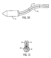
- FIG. 10 is a side view of a wye splice of the present disclosure.
- FIG. 11 is an end view of a wye splice of the present disclosure.
- FIG. 12 is a side perspective view of a cable support clamp of the present disclosure.
- FIG. 13 is a side view of a cable support clamp of the present disclosure.
- FIG. 14 is a front view of a cable support clamp of the present disclosure.
- FIG. 15 is a rear view of a cable support clamp of the present disclosure.
- FIGS. 16A-B are side perspective views of assembly of a cable support clamp of the present disclosure.
- FIG. 17 is a front perspective view of a cable hang-off of the present disclosure.
- FIG. 18 is a side perspective view of a shell of a cable hang-off of the present disclosure.
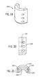
- FIG. 19 is a side perspective view of a shell half of a cable hang-off of the present disclosure.
- FIG. 20 is a side view of a shell half of a cable hang-off of the present disclosure.
- FIG. 21 is a top view of a shell half of a cable hang-off of the present disclosure.
- FIG. 22 is a rear view of a shell half of a cable hang-off of the present disclosure.
- FIG. 23 is a front perspective view of a slip of a cable hang-off of the present disclosure.
- FIG. 24 is a top view of a slip of a cable hang-off of the present disclosure.
- FIG. 25 is a side view of a slip of a cable hang-off of the present disclosure.
- FIG. 25A is an inset detail view of area 25 A of FIG. 25 .
- FIG. 26 is a front perspective view of a cable hang-off of the present disclosure being assembled over a proximal end of a coiled tubing.
- FIG. 27 is a side view of a cable hang-off of the present disclosure being assembled over a proximal end of a coiled tubing.
- FIG. 28 is a front perspective view of a cable hang-off of the present disclosure being assembled over a proximal end of a coiled tubing.
- FIG. 29 is a side view of a cable hang-off of the present disclosure being assembled using a pressure plate.
- FIG. 30 is a top view of a cable hang-off of the present disclosure being assembled using a pressure plate.
- FIG. 31 is a side view of a cable hang-off of the present disclosure being assembled using a pressure plate.
- FIG. 32 is a side view of a cable hang-off of the present disclosure being assembled using a pressure plate.
- FIG. 33 is a side perspective view of a wellhead termination assembly of the present disclosure, shown with the terminal spool in broken lines.
- FIG. 34 is a side view of a wellhead termination assembly of the present disclosure, shown with the terminal spool removed.
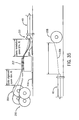
- FIG. 35 is a plan view of a method of manufacturing the heating apparatus according to the present disclosure.
- the present invention encompasses various embodiments of installing an electric heating apparatus downhole within the production tubing 100 of a wellbore 102 for the purpose of providing thermal (heat) energy to the production tubing 100 , the wellbore 102 , the medium contained in the wellbore 102 , or the surrounding environment (i.e., reservoir).
- the apparatus can include a length of coiled tubing 40 containing one or more electric heating cables that provide the thermal energy.
- the coiled tubing 40 extends from a proximal end at or near the wellhead 104 downhole a predetermined distance to a distal end, which may be at, short of, or beyond the bottom of the production tubing 100 .
- a tubing plug 42 located at or near the bottom end of the coiled tubing 40 can provide a pressure-tight seal between the coiled tubing 40 and the surrounding environment.
- the coiled tubing 40 can be attached at its proximal end to a wellhead termination assembly 50 .
- the wellhead termination assembly 50 can include a coiled tubing hanger 52 , a termination spool 54 disposed above the coiled tubing hanger 52 , and a wellhead cable hang-off 56 disposed within the termination spool 54 .
- the coiled tubing hanger 52 hangs the coiled tubing 40 at its proximal end, substantially coaxially with the production tubing 100 as is known in the art, allowing the proximal end of the coiled tubing 40 to interface with the cable hang-off 56 .
- the terminal spool 54 is a hollow metal cylinder that contains and protects the cable hang-off 56 and the heater termination attachments 58 for one or more electrical heating cables 70 .
- the heater termination attachments 58 can be attached to a cold lead of each heating cable 70 .
- An electrical feedthrough 60 in the terminal spool 54 receives connecting wires 62 that connect to the termination attachments 58 and deliver power to the heating cables 70 from the transformer 66 .
- a heater control panel 68 can be disposed in the electrical circuit that includes the cables 70 , in order to control power supplied to the cables 70 .
- the coiled tubing 40 can contain one or more electrical heating cables 70 , such as MI cables or polymer insulated cables, that extend along all or most of the length of the coiled tubing 40 and are isolated, and thereby protected, from the surrounding wellbore 102 environment.
- the cables 70 are enclosed within the coiled tube 40 and sealed off from well fluids which often contain corrosive or harsh gases and liquids which can damage the cables 70 . Isolating the cables 70 from well fluids allows for the use of cables and related materials (such as, by way of illustration but not limitation, silver solder) that would otherwise not be possible in many applicable environments. Further, by allowing a broader range of materials to be used to construct the heating cables 70 and associated components, more cost effective systems can be manufactured.
- One or more of the cables 70 may be comprised of cable segments 70 A, B, C, and adjacent segments may be spliced together with an inline cable splice 72 .
- the inline cable splice 72 depicted in FIGS. 5-7 is a splice which can connect two or more heating cables from the same electrical circuit phase inline so as to facilitate longer circuit lengths.
- cable segments 70 A, B enter/exit the splice from opposite ends.
- one or more of the cables 70 can be comprised of segments 70 A-C with different properties in order to deliver different amounts of thermal energy along the length of the coiled tubing 40 .
- a cable 70 can have a cold lead 70 A that has a very narrow conductor or very thick insulator to radiate little or not thermal energy, a warm lead 70 B having properties that cause it to radiate some thermal energy, and a hot lead 70 C that comparatively delivers the most thermal energy to its surroundings.
- the lead segments 70 A-C can be further spliced with inline cable splices 72 as shown in FIG. 3 .
- Separate cables 70 may be spliced together or co-terminated with a wye splice 74 or end cap, respectively.
- the cable wye splice 74 (or end cap) depicted in FIGS. 8-11 is a splice which connects two or more cables 70 from different electrical circuit phases together to form a closed circuit at the electrical terminal (i.e., distal) end of the heater system. While the wye splice 74 is disposed at the distal end of the coiled tubing 40 in FIGS. 3 and 4 , it is not required to be so located, as it is possible to “loop back” cables 70 for some distance in order to increase power output in a portion of the coiled tubing 40 . Typically, all spliced cables 70 enter the wye splice 74 from the same end, and no cables 70 enter or exit the wye splice 74 from the opposite end.
- the coiled tubing 40 can further contain a high-strength, elongate support member 76 , such as a wire rope, extending along the length of the coiled tubing 40 substantially parallel and in proximity to the heating cables 70 .
- the support member 76 can be attached to the heating cables 70 for the purpose of transferring mechanical load onto the support member 76 .
- the support member 76 provides tensile strength for purposes of pulling the cables 70 into the coiled tubing 40 during the manufacturing or assembly process, and also for the purposes of providing additional tensile strength when the coiled tubing 40 and the cables 70 are disposed vertically inside the wellbore 102 or another installation.
- the support member 76 can be attached to some or all of the cables 70 at regular intervals along the length of the support member 76 with cable support clamps 80 .
- the cable support clamp 80 is used to make a mechanical connection between cables 70 and the elongate support member 76 in order to transfer mechanical loads from the cables 70 to the support member 76 .
- a cable support clamp 80 can attach all or a subset of the cables 70 to the support member 76 .
- FIGS. 12-16B illustrate an exemplary cable support clamp 80 for the heating system of FIGS. 3 and 4 , which has three cables 70 and one wire rope (i.e., support member 76 ).
- the cable support clamp 80 can include at least one clamp body 82 having a cylindrical center member 84 and substantially diametrically opposed wings 86 , 88 attached to or integral with the center member 84 at the outer surface of the cylinder.
- the center member 84 can include a centrally disposed bore 90 .
- the bore 90 may be partially or completely threaded for receiving a bolt 128 , or may be otherwise configured to receive an attachment device for attaching another clamp body 82 as described below.
- Each wing 86 , 88 is flush and coplanar with the rear of the center member 84 and is twice the length of the center member 84 in the axial direction, therefore extending past the front of the center member 84 for the length of the center member 84 .
- the front surfaces of the wings 86 , 88 are coplanar.
- a mounting channel 92 separates the wings 86 , 88 and is defined by an arcuate interior surface 92 A,B on each wing 86 , 88 that conforms to the diameter of the center member 84 .
- Each wing 86 , 88 can include one or more cavities that are configured to cooperate with corresponding cavities in the corresponding wing 86 , 88 of another clamp body 82 .
- a first wing 86 can include a first cable cavity 94 A and a second cable cavity 94 B, while the opposing second wing 88 can include a third cable cavity 94 C and a rope cavity 96 .
- the cable cavities 94 A-C each hold a cable 70 and therefore may be the same size (i.e., cavity radius).
- the rope cavity 96 can have a smaller radius than the cable cavities 94 A-C. Any of the cavities 94 A-C, 96 can further have a tapering profile, such that the cavity radius is larger at one end of the wing 88 than at the other.
- Each wing 86 , 88 can further include one or more grooves 98 disposed in the outer surface of the wing 86 , 88 .
- the grooves 98 can facilitate the passage of a fluid that is used to fill the coiled tubing 40 if the coiled tubing 40 is being filled as described below when the cable support clamps 80 are present therein.
- the cable support clamp 80 can include two substantially identical clamp bodies 82 oriented in opposite axial directions and at a 90-degree angle to each other. With the bores 90 of the clamp bodies 82 aligned, the clamp bodies 82 interface with each other, the central member 84 of one clamp body 82 sliding into the mounting channel 92 of the opposing clamp body until the central members 84 abut each other. A bolt 110 or other suitable attachment device can then be inserted through the bores 90 to attach the clamp bodies 82 to each other.
- Each cable cavity 94 A-C and the rope cavity 96 of one clamp body 82 cooperates with the corresponding cable cavities 94 A-C and rope cavity 96 of the other clamp body 82 to create clamp channels 97 A-D for each heating cable 70 and the support member 76 .
- a suitable interval for attaching the cable support clamps 80 can depend on several factors, including the length and diameter of the cables 70 and support member 76 , the trajectory of the wellbore 102 , and the inherent material tolerances of the cable support clamp 80 .
- the apparatus can include cable support clamps 80 of different sizes, including clamp body 82 size and clamp channel 97 A-D diameters, for different sized heating cables 70 .
- the material of the clamp bodies 82 can have high heat tolerance to resist deformation that might cause the cables 70 or support member 76 to slip at high temperatures.
- an apparatus disposed in vertically-hung and air-filled coiled tubing 40 and having three heating cables 70 and one wire rope as the support member 76 , has the following characteristics:
- the illustrated clamp 80 may be comprised substantially of carbon steel, in which case the clamps 80 of each of the three sizes needed for the working example can support a load of 275-300 lbs. at a temperature of 185 F-220 F.
- the clamp 80 can be stainless steel or another suitable material.
- the coiled tubing 40 may be filled with at least one fluid which serves a variety of beneficial purposes. Said at least one fluid can improve heat transfer between the cables and the tubing, thereby allowing higher power output and higher system operating temperature. Fluid filling also provides a means of tube integrity monitoring including, without limitation, by way of the measurement of the fluid pressure or level inside the tube. Fluid filling further provides a buoyancy effect on the heating cables 70 and support member 76 , relieving some of the mechanical load on the clamps 80 and cable hang-off 56 .
- the coiled tubing 40 can receive approximately 400 gal. of a dielectric fluid, such as transformer oil, mineral oil, or another dielectric oil, leaving a safety gap of about 250 ft. to the wellhead, allowing sufficient expansion volume of the fluid at expected temperatures to prevent an overflow and keep air pressures within the system at a manageable level. This configuration relieves about 800 lb. of the above hanging weight.
- the wellhead cable hang-off 56 can be used to suspend the cables 70 and support member 76 (e.g., wire rope) within the coiled tubing 40 or other structure, usually at the uppermost extent of the heater system where electrical power will be connected to the cables 70 .
- the cable hang-off 56 can provide the requisite mechanical support to hold the support member 56 at or near its proximal end, allowing the support member 56 and the cables 70 to extend downhole within the coiled tubing 40 .
- the cable hang-off 56 can include a shell 120 having a distal end that fits over the proximal end of the coiled tubing 40 , and a proximal end that receives a plurality of slips 130 .
- the shell 120 can be divided into two halves 120 A,B that can be identical, or at least substantially symmetrical.
- the halves 120 A,B can be semi-cylindrical, with planar faces that abut each other and receive bolts or other attachment devices to hold the halves 120 A,B together.
- Each half 120 A,B of the shell 120 has a plurality of cavities that cooperate with the cavities of the opposing half 120 A,B to form a plurality of receptacles in the shell 120 : the proximal cavities 122 A,B cooperate to form a conical bowl 122 that receives the slips 130 ; and, the distal cavities 124 A,B cooperate to form a cylindrical mount 124 that receives the proximal end of the coiled tubing 40 .
- the proximal face of the shell 120 can include a plurality of bolt holes 126 .
- the distal end of the shell 120 can be beveled.
- the slips 130 are wedge-shaped members that cooperate to form a conical pinching member that suspends the support member 76 via friction fit.
- the slip 130 tapers from a proximal end to a distal end, and has an arcuate outer surface 132 that conforms to the radius of the bowl 122 .
- the slip 130 can have first and second inner surfaces 134 , 136 that are adjacent to each end of the outer surface 132 .
- the first and second inner surfaces 134 , 136 are mirror images of each other, each having a planar portion 134 A, 136 A and an arcuate portion 134 B, 136 B.
- the first inner surface 134 cooperates with the second inner surface 136 of an adjacent slip 130 to form a cable channel 140 .
- the slip 130 can further have an arcuate gripping surface 138 positioned to cooperate with the gripping surfaces 138 of the other slips 130 to create a substantially circular gripping channel 142 that is coaxial with the shell 120 . See FIG. 17 .
- the gripping surface 138 may have studs, ribs, teeth, or other projections 138 A, as shown in FIG. 25A , that give the gripping channel 142 a slide-resistant surface.
- the halves 120 A,B of the shell 120 can be assembled over the coiled tubing 40 .
- three slips 130 assemble by being inserted into the bowl 122 to form the pinching member 144 , with the gripping channel 142 encircling and gripping the wire rope, and the cable channels 140 disposed around the cables 70 .
- the slips 130 can be mechanically inserted into the bowl 122 into contact with the wire rope so that the gripping channel 142 grips the wire rope.
- a pressure plate 150 as shown in FIGS. 29-32 can be used to mechanically urge the slips 130 into their tightest-fitting position.
- the pressure plate 150 can have an arm 152 for contacting each of the slips 130 .
- the arms 152 meet at the center of the pressure plate 150 , and can define a fitting recess 154 that surrounds the wire rope so that the wire rope is centered at the center of the pressure plate 150 .
- the pressure plate 150 can push the slips 130 into place, and then can be attached to the shell 120 , such as with one or more bolts driven into the bolt holes 126 .
- the proximal ends of the cables 70 can extend proximally out of the cable hang-off 56 and connect electrically to cable terminators 58 .
- the cable terminators 58 connect electrically to wires 62 that extend out of the termination spool 54 through the electrical feedthrough(s) 60 .
- Another feature or embodiment of the present invention comprises a method of manufacturing the apparatus by installing the cable into the coiled tubing 40 , such as with a sinker bar if the coiled tubing 40 is installed in a vertical well, or with a horizontal pull into horizontally-laid coiled tubing 40 .
- the coiled tubing 40 is laid flat and cut to length.
- One or more heating cable spools 200 each carrying a heating cable 70 , and a support member spool 202 are positioned at the distal (i.e., downhole) end of the coiled tubing 40 .
- a cable alignment space A and a clamp installation space B may be left between the spools 200 , 202 and the coiled tubing 40 .
- Protective members 204 such as one or more sheets of plywood, may be laid in the path between the spools 200 , 202 and the coiled tubing 40 .
- a funnel 210 can be attached to the distal end of the coiled tubing 40 to facilitate running the cables 70 .
- the cables 70 and support member 76 are paid out of the spools 200 , 202 .
- the cables 70 can be run through a cable straightener 212 with the support member 76 being drawn out of the way of (i.e. alongside, under, or over) the straightener 212 .
- proximal ends of the cables 70 and support member 76 are attached to a pull-rope 206 , which is disposed inside the coiled tubing 40 and attached to a pull-rope spool 208 at the proximal end of the coiled tubing 40 .
- the first clamp 80 is installed about one foot from the proximal ends of the cables 70 and support member 76 .
- the cables 70 and support member 76 are then drawn into the coiled tubing 40 by slowly retracting the pull-rope 206 .
- the clamps 80 can be continuously installed at the desired interval until the distal ends of the cables 70 are about three feet from the distal end of the coiled tubing 40 .
- the wye splice 74 can be installed on the distal ends of the cables 70 using any suitable connection method.
- the wye splice 74 can be pushed into the end of the coiled tubing 40 and the tubing plug 42 installed. At the proximal ends, any slack in the cables 70 can be pulled out, and then the cables 70 and support member 76 can be separated from the pull-rope 206 and cut back to a desired length. Where the support member 76 is a wire rope, the wire rope can be left about one foot longer than the cables 70 to facilitate looping and crimping the wire rope for hanging.
- the coiled tubing 40 with the cables 70 , support member 76 , and clamps 80 installed can then be wound onto a shipping spool (not shown).
- Another feature or embodiment of the present invention comprises a method of installing the apparatus in a wellbore 102 .
- the shipping spool and cable hang-off 56 are delivered to the installation site.
- the coiled tubing 40 is deployed into the production tubing 100 and then suspended by the coiled tubing hanger 52 as is known in the art, while the proximal end of the support member 76 is attached to a temporary hanging device, such as by placing the crimped loop on a hook (not shown in FIGS.).
- the shell 120 of the cable hang-off 56 can be split into its halves 120 A,B, see FIG.
- the cables 70 are spread apart and the pressure plate 150 is inserted around the support member 76 . See FIGS. 29, 30 .
- the slips 130 are then positioned over the bowl 122 in contact with the underside of the pressure plate 150 , see FIG. 31 , and then driven into place in the bowl 122 . See FIGS. 28 and 32 .
- the pressure plate 150 can be attached to the shell 120 with bolts or other attachment devices. See FIG. 32 .
- the slips 130 thereby form the pinching member 144 having its tightest-fitting position, gripping the support member 76 .
- the tension of the temporary hanging device can be drawn to zero to test for slippage of the support member 76 within the gripping channel 142 . If there is no slippage, the support member 76 can be cut or otherwise removed from the temporary hanging device and the termination attachments 128 can be attached to the cables 70 . See FIG. 34 .
- Structural/functional differences between the present invention and the prior art include, without limitation, the following:
- Heater elements are protected from wellbore fluids
- dielectric fluid(s) for heat transfer, tube integrity monitoring (through pressure monitoring and/or other methods) and improved dielectric performance;
Landscapes
- Engineering & Computer Science (AREA)
- Life Sciences & Earth Sciences (AREA)
- Geology (AREA)
- Mining & Mineral Resources (AREA)
- Physics & Mathematics (AREA)
- Environmental & Geological Engineering (AREA)
- Fluid Mechanics (AREA)
- General Life Sciences & Earth Sciences (AREA)
- Geochemistry & Mineralogy (AREA)
- Mechanical Engineering (AREA)
- Pipe Accessories (AREA)
Abstract
Description
| Free-hanging cable total length | 5195 | ft. |
| | 320 ft./0.496 in. |
| | 3395 ft./0.355 in. |
| | 1500 ft./0.286 in. |
| Approx. hanging weight of | 10,134 | lb. |
| | 100 | ft. (75 ft. |
| in | ||
| lead | ||
| segment | ||
| 70A) | ||
| | 6/115 | lb. |
| | 34/75 | lb. |
| | 15/48 | lb. |
The illustrated
Claims (20)
Priority Applications (1)
| Application Number | Priority Date | Filing Date | Title |
|---|---|---|---|
| US14/033,072 US9416640B2 (en) | 2012-09-20 | 2013-09-20 | Downhole wellbore heating system and method |
Applications Claiming Priority (2)
| Application Number | Priority Date | Filing Date | Title |
|---|---|---|---|
| US201261703464P | 2012-09-20 | 2012-09-20 | |
| US14/033,072 US9416640B2 (en) | 2012-09-20 | 2013-09-20 | Downhole wellbore heating system and method |
Publications (2)
| Publication Number | Publication Date |
|---|---|
| US20140099084A1 US20140099084A1 (en) | 2014-04-10 |
| US9416640B2 true US9416640B2 (en) | 2016-08-16 |
Family
ID=50342084
Family Applications (1)
| Application Number | Title | Priority Date | Filing Date |
|---|---|---|---|
| US14/033,072 Active 2035-02-11 US9416640B2 (en) | 2012-09-20 | 2013-09-20 | Downhole wellbore heating system and method |
Country Status (3)
| Country | Link |
|---|---|
| US (1) | US9416640B2 (en) |
| EP (2) | EP2898180B1 (en) |
| WO (1) | WO2014047469A2 (en) |
Cited By (1)
| Publication number | Priority date | Publication date | Assignee | Title |
|---|---|---|---|---|
| US10947817B2 (en) | 2018-08-14 | 2021-03-16 | Robert C Kramm | Methods and systems for a tool with encapsulated heating cable within a wellbore |
Families Citing this family (6)
| Publication number | Priority date | Publication date | Assignee | Title |
|---|---|---|---|---|
| WO2015176172A1 (en) * | 2014-02-18 | 2015-11-26 | Athabasca Oil Corporation | Cable-based well heater |
| WO2018111689A1 (en) * | 2016-12-12 | 2018-06-21 | Shell Oil Company | Method and assembly for downhole deployment of well instrumentation |
| GB201701118D0 (en) * | 2017-01-23 | 2017-03-08 | Kinder Mark | Resin free hang-off for subsea power cables to offshore wind turbines |
| CN112228025B (en) * | 2019-07-15 | 2024-06-25 | 久盛电气股份有限公司 | Oil well pump electric heating protection pipe string |
| CN114135262B (en) * | 2021-11-17 | 2024-05-07 | 中国石油天然气股份有限公司 | Downhole steam secondary electric heating pipe string and heating method |
| CN118462111A (en) * | 2024-07-15 | 2024-08-09 | 山东华宁电伴热科技有限公司 | A heating device for deep sea oil production |
Citations (32)
| Publication number | Priority date | Publication date | Assignee | Title |
|---|---|---|---|---|
| US1169262A (en) * | 1915-05-27 | 1916-01-25 | William Daniel Huff | Electric heater. |
| US1700336A (en) | 1923-05-26 | 1929-01-29 | Casper L Redfield | Measuring device for oil wells |
| US3713482A (en) | 1971-05-04 | 1973-01-30 | H Lichte | Gas flow regulator for wellbore catalytic heaters |
| US3780803A (en) | 1971-05-17 | 1973-12-25 | Sun Oil Co | Downhole control valve for catalytic wellbore heaters |
| US3804163A (en) | 1972-06-08 | 1974-04-16 | Sun Oil Co | Catalytic wellbore heater |
| US3912445A (en) | 1974-03-25 | 1975-10-14 | Phillips Petroleum Co | Mechanism for inserting heater in parison which moves in arcuate path |
| US4545442A (en) | 1981-10-05 | 1985-10-08 | Warner Bert J | Method and apparatus for forming a heat exchange system in the earth |
| US5070533A (en) | 1990-11-07 | 1991-12-03 | Uentech Corporation | Robust electrical heating systems for mineral wells |
| US5252808A (en) * | 1991-11-22 | 1993-10-12 | Phillips Petroleum Company | Method and apparatus for recovering petroleum residues from storage sites |
| US5623576A (en) * | 1993-07-26 | 1997-04-22 | Meshekow Oil Recovery Corporation | Downhole radial flow steam generator for oil wells |
| US6250371B1 (en) | 1995-09-12 | 2001-06-26 | Enlink Geoenergy Services, Inc. | Energy transfer systems |
| US6276438B1 (en) | 1995-09-12 | 2001-08-21 | Thomas R. Amerman | Energy systems |
| US6360819B1 (en) | 1998-02-24 | 2002-03-26 | Shell Oil Company | Electrical heater |
| US6585036B2 (en) | 1995-09-12 | 2003-07-01 | Enlink Geoenergy Services, Inc. | Energy systems |
| US6672371B1 (en) | 1995-09-12 | 2004-01-06 | Enlink Geoenergy Services, Inc. | Earth heat exchange system |
| US6896063B2 (en) | 2003-04-07 | 2005-05-24 | Shell Oil Company | Methods of using downhole polymer plug |
| US7017650B2 (en) | 1995-09-12 | 2006-03-28 | Enlink Geoenergy Services, Inc. | Earth loop energy systems |
| US7051811B2 (en) | 2001-04-24 | 2006-05-30 | Shell Oil Company | In situ thermal processing through an open wellbore in an oil shale formation |
| US7090013B2 (en) | 2001-10-24 | 2006-08-15 | Shell Oil Company | In situ thermal processing of a hydrocarbon containing formation to produce heated fluids |
| US20070133959A1 (en) * | 2005-04-22 | 2007-06-14 | Vinegar Harold J | Grouped exposed metal heaters |
| US7367399B2 (en) | 2003-10-06 | 2008-05-06 | Halliburton Energy Services, Inc. | Loop systems and methods of using the same for conveying and distributing thermal energy into a wellbore |
| US7398823B2 (en) * | 2005-01-10 | 2008-07-15 | Conocophillips Company | Selective electromagnetic production tool |
| CA2679994A1 (en) | 2007-02-07 | 2008-08-14 | Schlumberger Canada Limited | Active cable for wellbore heating and distributed temperature sensing |
| US20090260809A1 (en) | 2008-04-18 | 2009-10-22 | Scott Lee Wellington | Method for treating a hydrocarbon containing formation |
| US7753344B1 (en) | 2007-11-19 | 2010-07-13 | Moretz Benny W | Pressurized wire line spool and method for using same in conjunction with a universal radial carrier |
| US7891416B2 (en) | 2005-01-11 | 2011-02-22 | Amp-Lift Group Llc | Apparatus for treating fluid streams cross-reference to related applications |
| US20110259580A1 (en) | 2008-12-19 | 2011-10-27 | Artificial Lift Company Limited | Cables for downhole use |
| US8087460B2 (en) | 2007-03-22 | 2012-01-03 | Exxonmobil Upstream Research Company | Granular electrical connections for in situ formation heating |
| US20120080419A1 (en) | 2010-09-22 | 2012-04-05 | Aurora Optics, Inc. | Clip-on Heater |
| US8151877B2 (en) | 2007-05-15 | 2012-04-10 | Exxonmobil Upstream Research Company | Downhole burner wells for in situ conversion of organic-rich rock formations |
| US8353347B2 (en) * | 2008-10-13 | 2013-01-15 | Shell Oil Company | Deployment of insulated conductors for treating subsurface formations |
| US8622133B2 (en) | 2007-03-22 | 2014-01-07 | Exxonmobil Upstream Research Company | Resistive heater for in situ formation heating |
Family Cites Families (6)
| Publication number | Priority date | Publication date | Assignee | Title |
|---|---|---|---|---|
| US4600054A (en) | 1984-03-30 | 1986-07-15 | Equipment Renewal Company | Tubing hanger assembly |
| WO1994025726A1 (en) * | 1993-04-29 | 1994-11-10 | Moore Boyd B | Seal electrical conductor arrangement for use with a well bore in hazardous areas |
| US7748444B2 (en) * | 2007-03-02 | 2010-07-06 | Schlumberger Technology Corporation | Method and apparatus for connecting, installing, and retrieving a coiled tubing-conveyed electrical submersible pump |
| WO2009042575A1 (en) | 2007-09-26 | 2009-04-02 | Tyco Thermal Controls Llc | Skin effect heating system having improved heat transfer and wire support characteristics |
| US8186445B2 (en) * | 2009-04-23 | 2012-05-29 | Vetco Gray Inc. | System, method and apparatus for thermal wellhead having high power cable for in-situ upgrading processing |
| GB201012319D0 (en) * | 2010-07-22 | 2010-09-08 | Artificial Lift Co Ltd | Cables for downhole use |
-
2013
- 2013-09-20 WO PCT/US2013/060977 patent/WO2014047469A2/en not_active Ceased
- 2013-09-20 EP EP13839187.5A patent/EP2898180B1/en not_active Not-in-force
- 2013-09-20 EP EP18150863.1A patent/EP3348783B1/en active Active
- 2013-09-20 US US14/033,072 patent/US9416640B2/en active Active
Patent Citations (33)
| Publication number | Priority date | Publication date | Assignee | Title |
|---|---|---|---|---|
| US1169262A (en) * | 1915-05-27 | 1916-01-25 | William Daniel Huff | Electric heater. |
| US1700336A (en) | 1923-05-26 | 1929-01-29 | Casper L Redfield | Measuring device for oil wells |
| US3713482A (en) | 1971-05-04 | 1973-01-30 | H Lichte | Gas flow regulator for wellbore catalytic heaters |
| US3780803A (en) | 1971-05-17 | 1973-12-25 | Sun Oil Co | Downhole control valve for catalytic wellbore heaters |
| US3804163A (en) | 1972-06-08 | 1974-04-16 | Sun Oil Co | Catalytic wellbore heater |
| US3912445A (en) | 1974-03-25 | 1975-10-14 | Phillips Petroleum Co | Mechanism for inserting heater in parison which moves in arcuate path |
| US4545442A (en) | 1981-10-05 | 1985-10-08 | Warner Bert J | Method and apparatus for forming a heat exchange system in the earth |
| US5070533A (en) | 1990-11-07 | 1991-12-03 | Uentech Corporation | Robust electrical heating systems for mineral wells |
| US5252808A (en) * | 1991-11-22 | 1993-10-12 | Phillips Petroleum Company | Method and apparatus for recovering petroleum residues from storage sites |
| US5623576A (en) * | 1993-07-26 | 1997-04-22 | Meshekow Oil Recovery Corporation | Downhole radial flow steam generator for oil wells |
| US7017650B2 (en) | 1995-09-12 | 2006-03-28 | Enlink Geoenergy Services, Inc. | Earth loop energy systems |
| US6585036B2 (en) | 1995-09-12 | 2003-07-01 | Enlink Geoenergy Services, Inc. | Energy systems |
| US6672371B1 (en) | 1995-09-12 | 2004-01-06 | Enlink Geoenergy Services, Inc. | Earth heat exchange system |
| US6250371B1 (en) | 1995-09-12 | 2001-06-26 | Enlink Geoenergy Services, Inc. | Energy transfer systems |
| US6276438B1 (en) | 1995-09-12 | 2001-08-21 | Thomas R. Amerman | Energy systems |
| US6360819B1 (en) | 1998-02-24 | 2002-03-26 | Shell Oil Company | Electrical heater |
| US7051811B2 (en) | 2001-04-24 | 2006-05-30 | Shell Oil Company | In situ thermal processing through an open wellbore in an oil shale formation |
| US7090013B2 (en) | 2001-10-24 | 2006-08-15 | Shell Oil Company | In situ thermal processing of a hydrocarbon containing formation to produce heated fluids |
| US6896063B2 (en) | 2003-04-07 | 2005-05-24 | Shell Oil Company | Methods of using downhole polymer plug |
| US7367399B2 (en) | 2003-10-06 | 2008-05-06 | Halliburton Energy Services, Inc. | Loop systems and methods of using the same for conveying and distributing thermal energy into a wellbore |
| US7398823B2 (en) * | 2005-01-10 | 2008-07-15 | Conocophillips Company | Selective electromagnetic production tool |
| US7891416B2 (en) | 2005-01-11 | 2011-02-22 | Amp-Lift Group Llc | Apparatus for treating fluid streams cross-reference to related applications |
| US20070133959A1 (en) * | 2005-04-22 | 2007-06-14 | Vinegar Harold J | Grouped exposed metal heaters |
| CA2679994A1 (en) | 2007-02-07 | 2008-08-14 | Schlumberger Canada Limited | Active cable for wellbore heating and distributed temperature sensing |
| US7730936B2 (en) | 2007-02-07 | 2010-06-08 | Schlumberger Technology Corporation | Active cable for wellbore heating and distributed temperature sensing |
| US8087460B2 (en) | 2007-03-22 | 2012-01-03 | Exxonmobil Upstream Research Company | Granular electrical connections for in situ formation heating |
| US8622133B2 (en) | 2007-03-22 | 2014-01-07 | Exxonmobil Upstream Research Company | Resistive heater for in situ formation heating |
| US8151877B2 (en) | 2007-05-15 | 2012-04-10 | Exxonmobil Upstream Research Company | Downhole burner wells for in situ conversion of organic-rich rock formations |
| US7753344B1 (en) | 2007-11-19 | 2010-07-13 | Moretz Benny W | Pressurized wire line spool and method for using same in conjunction with a universal radial carrier |
| US20090260809A1 (en) | 2008-04-18 | 2009-10-22 | Scott Lee Wellington | Method for treating a hydrocarbon containing formation |
| US8353347B2 (en) * | 2008-10-13 | 2013-01-15 | Shell Oil Company | Deployment of insulated conductors for treating subsurface formations |
| US20110259580A1 (en) | 2008-12-19 | 2011-10-27 | Artificial Lift Company Limited | Cables for downhole use |
| US20120080419A1 (en) | 2010-09-22 | 2012-04-05 | Aurora Optics, Inc. | Clip-on Heater |
Cited By (1)
| Publication number | Priority date | Publication date | Assignee | Title |
|---|---|---|---|---|
| US10947817B2 (en) | 2018-08-14 | 2021-03-16 | Robert C Kramm | Methods and systems for a tool with encapsulated heating cable within a wellbore |
Also Published As
| Publication number | Publication date |
|---|---|
| EP2898180B1 (en) | 2018-01-10 |
| EP3348783B1 (en) | 2020-07-15 |
| US20140099084A1 (en) | 2014-04-10 |
| WO2014047469A3 (en) | 2014-05-15 |
| EP2898180A4 (en) | 2016-12-21 |
| WO2014047469A2 (en) | 2014-03-27 |
| EP3348783A1 (en) | 2018-07-18 |
| EP2898180A2 (en) | 2015-07-29 |
Similar Documents
| Publication | Publication Date | Title |
|---|---|---|
| EP2898180B1 (en) | Downhole wellbore heating system and method | |
| US8931552B2 (en) | Cables for downhole use | |
| DE112012003573B4 (en) | Electric current device, connector and submersible pump system | |
| BRPI0706452A2 (en) | apparatus and method for installing a control line and a pipe column in a well and method for attaching a control line to a pipe column | |
| US9822592B2 (en) | Cable-based well heater | |
| EP0565287B1 (en) | Undulated conduit anchored in coiled tubing | |
| US4051456A (en) | Apparatus for establishing and maintaining electric continuity in drill pipe | |
| US9074592B2 (en) | Deployment of downhole pump using a cable | |
| US20050045343A1 (en) | A Conduit Having a Cable Therein | |
| BRPI0706455A2 (en) | upper control line feed to raised table tripod | |
| BR102013012986A2 (en) | Assembly, and method | |
| CA2907922C (en) | Methods and systems for deploying cable into a well | |
| CA2245502C (en) | Method of suspending an esp within a wellbore | |
| NO314854B1 (en) | Method of hanging a submersible pump system in a borehole | |
| US10731434B2 (en) | Hanger assembly with penetrators | |
| US10544632B2 (en) | Coiled tubing electrical power splice | |
| WO2016130147A1 (en) | Shape memory alloy rope socket for a downhole tool | |
| AU2020332078B2 (en) | Subsea umbilicals | |
| US11713626B2 (en) | Spoolable splice connector and method for tubing encapsulated cable | |
| CN107013177B (en) | Wellhead hanger for heating umbilical | |
| US20190106955A1 (en) | Load Reduction Device And Method For Reducing Load on Power Cable Coiled Tubing |
Legal Events
| Date | Code | Title | Description |
|---|---|---|---|
| AS | Assignment |
Owner name: PENTAIR THERMAL MANAGEMENT LLC, CALIFORNIA Free format text: ASSIGNMENT OF ASSIGNORS INTEREST;ASSIGNORS:PARMAN, DAVID G.;O'BRIEN, KELLY;FARZANEH, FARDIN;SIGNING DATES FROM 20131113 TO 20131120;REEL/FRAME:031792/0499 |
|
| STCF | Information on status: patent grant |
Free format text: PATENTED CASE |
|
| AS | Assignment |
Owner name: PENTAIR FLOW SERVICES AG, SWITZERLAND Free format text: ASSIGNMENT OF ASSIGNORS INTEREST;ASSIGNOR:PENTAIR THERMAL MANAGEMENT LLC;REEL/FRAME:045403/0645 Effective date: 20170427 |
|
| AS | Assignment |
Owner name: NVENT SERVICES GMBH, SWITZERLAND Free format text: ASSIGNMENT OF ASSIGNORS INTEREST;ASSIGNOR:PENTAIR FLOW SERVICES AG;REEL/FRAME:045662/0549 Effective date: 20180424 |
|
| MAFP | Maintenance fee payment |
Free format text: PAYMENT OF MAINTENANCE FEE, 4TH YEAR, LARGE ENTITY (ORIGINAL EVENT CODE: M1551); ENTITY STATUS OF PATENT OWNER: LARGE ENTITY Year of fee payment: 4 |
|
| MAFP | Maintenance fee payment |
Free format text: PAYMENT OF MAINTENANCE FEE, 8TH YEAR, LARGE ENTITY (ORIGINAL EVENT CODE: M1552); ENTITY STATUS OF PATENT OWNER: LARGE ENTITY Year of fee payment: 8 |
|
| AS | Assignment |
Owner name: CHEMELEX EUROPE GMBH, SWITZERLAND Free format text: ASSIGNMENT OF ASSIGNORS INTEREST;ASSIGNOR:NVENT SERVICES GMB;REEL/FRAME:074842/0256 Effective date: 20251105 |