US9416519B2 - Wheel loader - Google Patents
Wheel loader Download PDFInfo
- Publication number
- US9416519B2 US9416519B2 US14/781,842 US201414781842A US9416519B2 US 9416519 B2 US9416519 B2 US 9416519B2 US 201414781842 A US201414781842 A US 201414781842A US 9416519 B2 US9416519 B2 US 9416519B2
- Authority
- US
- United States
- Prior art keywords
- hydraulic
- engine
- mechanical drive
- gear
- switching
- Prior art date
- Legal status (The legal status is an assumption and is not a legal conclusion. Google has not performed a legal analysis and makes no representation as to the accuracy of the status listed.)
- Expired - Fee Related
Links
- 230000005540 biological transmission Effects 0.000 claims abstract description 75
- 239000010720 hydraulic oil Substances 0.000 claims abstract description 24
- 238000006073 displacement reaction Methods 0.000 claims description 40
- 239000000446 fuel Substances 0.000 claims description 21
- 238000002347 injection Methods 0.000 claims description 9
- 239000007924 injection Substances 0.000 claims description 9
- 230000001133 acceleration Effects 0.000 claims description 6
- 238000011144 upstream manufacturing Methods 0.000 claims description 5
- 230000035939 shock Effects 0.000 description 25
- 238000000034 method Methods 0.000 description 19
- 230000008569 process Effects 0.000 description 18
- 238000000418 atomic force spectrum Methods 0.000 description 15
- 230000002411 adverse Effects 0.000 description 5
- 230000007246 mechanism Effects 0.000 description 5
- 230000002457 bidirectional effect Effects 0.000 description 4
- 230000008859 change Effects 0.000 description 4
- 238000009412 basement excavation Methods 0.000 description 3
- 238000001514 detection method Methods 0.000 description 2
- 238000010586 diagram Methods 0.000 description 2
- 230000009347 mechanical transmission Effects 0.000 description 2
- 230000003068 static effect Effects 0.000 description 2
- 230000002706 hydrostatic effect Effects 0.000 description 1
- 239000002184 metal Substances 0.000 description 1
- 230000004048 modification Effects 0.000 description 1
- 238000012986 modification Methods 0.000 description 1
- 230000002265 prevention Effects 0.000 description 1
- 230000004044 response Effects 0.000 description 1
- 239000004576 sand Substances 0.000 description 1
- 239000002689 soil Substances 0.000 description 1
Images


Classifications
-
- E—FIXED CONSTRUCTIONS
- E02—HYDRAULIC ENGINEERING; FOUNDATIONS; SOIL SHIFTING
- E02F—DREDGING; SOIL-SHIFTING
- E02F9/00—Component parts of dredgers or soil-shifting machines, not restricted to one of the kinds covered by groups E02F3/00 - E02F7/00
- E02F9/20—Drives; Control devices
- E02F9/22—Hydraulic or pneumatic drives
- E02F9/2253—Controlling the travelling speed of vehicles, e.g. adjusting travelling speed according to implement loads, control of hydrostatic transmission
-
- E—FIXED CONSTRUCTIONS
- E02—HYDRAULIC ENGINEERING; FOUNDATIONS; SOIL SHIFTING
- E02F—DREDGING; SOIL-SHIFTING
- E02F3/00—Dredgers; Soil-shifting machines
- E02F3/04—Dredgers; Soil-shifting machines mechanically-driven
- E02F3/28—Dredgers; Soil-shifting machines mechanically-driven with digging tools mounted on a dipper- or bucket-arm, i.e. there is either one arm or a pair of arms, e.g. dippers, buckets
- E02F3/34—Dredgers; Soil-shifting machines mechanically-driven with digging tools mounted on a dipper- or bucket-arm, i.e. there is either one arm or a pair of arms, e.g. dippers, buckets with bucket-arms, i.e. a pair of arms, e.g. manufacturing processes, form, geometry, material of bucket-arms directly pivoted on the frames of tractors or self-propelled machines
-
- E—FIXED CONSTRUCTIONS
- E02—HYDRAULIC ENGINEERING; FOUNDATIONS; SOIL SHIFTING
- E02F—DREDGING; SOIL-SHIFTING
- E02F3/00—Dredgers; Soil-shifting machines
- E02F3/04—Dredgers; Soil-shifting machines mechanically-driven
- E02F3/28—Dredgers; Soil-shifting machines mechanically-driven with digging tools mounted on a dipper- or bucket-arm, i.e. there is either one arm or a pair of arms, e.g. dippers, buckets
- E02F3/36—Component parts
- E02F3/42—Drives for dippers, buckets, dipper-arms or bucket-arms
- E02F3/422—Drive systems for bucket-arms, front-end loaders, dumpers or the like
-
- E—FIXED CONSTRUCTIONS
- E02—HYDRAULIC ENGINEERING; FOUNDATIONS; SOIL SHIFTING
- E02F—DREDGING; SOIL-SHIFTING
- E02F9/00—Component parts of dredgers or soil-shifting machines, not restricted to one of the kinds covered by groups E02F3/00 - E02F7/00
- E02F9/20—Drives; Control devices
- E02F9/2058—Electric or electro-mechanical or mechanical control devices of vehicle sub-units
- E02F9/2062—Control of propulsion units
-
- E—FIXED CONSTRUCTIONS
- E02—HYDRAULIC ENGINEERING; FOUNDATIONS; SOIL SHIFTING
- E02F—DREDGING; SOIL-SHIFTING
- E02F9/00—Component parts of dredgers or soil-shifting machines, not restricted to one of the kinds covered by groups E02F3/00 - E02F7/00
- E02F9/20—Drives; Control devices
- E02F9/2058—Electric or electro-mechanical or mechanical control devices of vehicle sub-units
- E02F9/2079—Control of mechanical transmission
-
- E—FIXED CONSTRUCTIONS
- E02—HYDRAULIC ENGINEERING; FOUNDATIONS; SOIL SHIFTING
- E02F—DREDGING; SOIL-SHIFTING
- E02F9/00—Component parts of dredgers or soil-shifting machines, not restricted to one of the kinds covered by groups E02F3/00 - E02F7/00
- E02F9/20—Drives; Control devices
- E02F9/22—Hydraulic or pneumatic drives
- E02F9/2278—Hydraulic circuits
- E02F9/2296—Systems with a variable displacement pump
-
- F—MECHANICAL ENGINEERING; LIGHTING; HEATING; WEAPONS; BLASTING
- F16—ENGINEERING ELEMENTS AND UNITS; GENERAL MEASURES FOR PRODUCING AND MAINTAINING EFFECTIVE FUNCTIONING OF MACHINES OR INSTALLATIONS; THERMAL INSULATION IN GENERAL
- F16H—GEARING
- F16H47/00—Combinations of mechanical gearing with fluid clutches or fluid gearing
- F16H47/02—Combinations of mechanical gearing with fluid clutches or fluid gearing the fluid gearing being of the volumetric type
- F16H47/04—Combinations of mechanical gearing with fluid clutches or fluid gearing the fluid gearing being of the volumetric type the mechanical gearing being of the type with members having orbital motion
-
- F—MECHANICAL ENGINEERING; LIGHTING; HEATING; WEAPONS; BLASTING
- F16—ENGINEERING ELEMENTS AND UNITS; GENERAL MEASURES FOR PRODUCING AND MAINTAINING EFFECTIVE FUNCTIONING OF MACHINES OR INSTALLATIONS; THERMAL INSULATION IN GENERAL
- F16H—GEARING
- F16H61/00—Control functions within control units of change-speed- or reversing-gearings for conveying rotary motion ; Control of exclusively fluid gearing, friction gearing, gearings with endless flexible members or other particular types of gearing
- F16H61/02—Control functions within control units of change-speed- or reversing-gearings for conveying rotary motion ; Control of exclusively fluid gearing, friction gearing, gearings with endless flexible members or other particular types of gearing characterised by the signals used
-
- F—MECHANICAL ENGINEERING; LIGHTING; HEATING; WEAPONS; BLASTING
- F16—ENGINEERING ELEMENTS AND UNITS; GENERAL MEASURES FOR PRODUCING AND MAINTAINING EFFECTIVE FUNCTIONING OF MACHINES OR INSTALLATIONS; THERMAL INSULATION IN GENERAL
- F16H—GEARING
- F16H61/00—Control functions within control units of change-speed- or reversing-gearings for conveying rotary motion ; Control of exclusively fluid gearing, friction gearing, gearings with endless flexible members or other particular types of gearing
- F16H61/04—Smoothing ratio shift
- F16H61/0437—Smoothing ratio shift by using electrical signals
-
- F—MECHANICAL ENGINEERING; LIGHTING; HEATING; WEAPONS; BLASTING
- F16—ENGINEERING ELEMENTS AND UNITS; GENERAL MEASURES FOR PRODUCING AND MAINTAINING EFFECTIVE FUNCTIONING OF MACHINES OR INSTALLATIONS; THERMAL INSULATION IN GENERAL
- F16H—GEARING
- F16H61/00—Control functions within control units of change-speed- or reversing-gearings for conveying rotary motion ; Control of exclusively fluid gearing, friction gearing, gearings with endless flexible members or other particular types of gearing
- F16H61/38—Control of exclusively fluid gearing
- F16H61/40—Control of exclusively fluid gearing hydrostatic
- F16H61/42—Control of exclusively fluid gearing hydrostatic involving adjustment of a pump or motor with adjustable output or capacity
- F16H61/421—Motor capacity control by electro-hydraulic control means, e.g. using solenoid valves
-
- F—MECHANICAL ENGINEERING; LIGHTING; HEATING; WEAPONS; BLASTING
- F16—ENGINEERING ELEMENTS AND UNITS; GENERAL MEASURES FOR PRODUCING AND MAINTAINING EFFECTIVE FUNCTIONING OF MACHINES OR INSTALLATIONS; THERMAL INSULATION IN GENERAL
- F16H—GEARING
- F16H61/00—Control functions within control units of change-speed- or reversing-gearings for conveying rotary motion ; Control of exclusively fluid gearing, friction gearing, gearings with endless flexible members or other particular types of gearing
- F16H61/38—Control of exclusively fluid gearing
- F16H61/40—Control of exclusively fluid gearing hydrostatic
- F16H61/42—Control of exclusively fluid gearing hydrostatic involving adjustment of a pump or motor with adjustable output or capacity
- F16H61/431—Pump capacity control by electro-hydraulic control means, e.g. using solenoid valves
-
- F—MECHANICAL ENGINEERING; LIGHTING; HEATING; WEAPONS; BLASTING
- F16—ENGINEERING ELEMENTS AND UNITS; GENERAL MEASURES FOR PRODUCING AND MAINTAINING EFFECTIVE FUNCTIONING OF MACHINES OR INSTALLATIONS; THERMAL INSULATION IN GENERAL
- F16H—GEARING
- F16H61/00—Control functions within control units of change-speed- or reversing-gearings for conveying rotary motion ; Control of exclusively fluid gearing, friction gearing, gearings with endless flexible members or other particular types of gearing
- F16H61/38—Control of exclusively fluid gearing
- F16H61/40—Control of exclusively fluid gearing hydrostatic
- F16H61/46—Automatic regulation in accordance with output requirements
- F16H61/462—Automatic regulation in accordance with output requirements for achieving a target speed ratio
-
- B—PERFORMING OPERATIONS; TRANSPORTING
- B60—VEHICLES IN GENERAL
- B60Y—INDEXING SCHEME RELATING TO ASPECTS CROSS-CUTTING VEHICLE TECHNOLOGY
- B60Y2200/00—Type of vehicle
- B60Y2200/40—Special vehicles
- B60Y2200/41—Construction vehicles, e.g. graders, excavators
- B60Y2200/415—Wheel loaders
-
- F—MECHANICAL ENGINEERING; LIGHTING; HEATING; WEAPONS; BLASTING
- F16—ENGINEERING ELEMENTS AND UNITS; GENERAL MEASURES FOR PRODUCING AND MAINTAINING EFFECTIVE FUNCTIONING OF MACHINES OR INSTALLATIONS; THERMAL INSULATION IN GENERAL
- F16H—GEARING
- F16H37/00—Combinations of mechanical gearings, not provided for in groups F16H1/00 - F16H35/00
- F16H37/02—Combinations of mechanical gearings, not provided for in groups F16H1/00 - F16H35/00 comprising essentially only toothed or friction gearings
- F16H37/06—Combinations of mechanical gearings, not provided for in groups F16H1/00 - F16H35/00 comprising essentially only toothed or friction gearings with a plurality of driving or driven shafts; with arrangements for dividing torque between two or more intermediate shafts
- F16H37/08—Combinations of mechanical gearings, not provided for in groups F16H1/00 - F16H35/00 comprising essentially only toothed or friction gearings with a plurality of driving or driven shafts; with arrangements for dividing torque between two or more intermediate shafts with differential gearing
- F16H37/0833—Combinations of mechanical gearings, not provided for in groups F16H1/00 - F16H35/00 comprising essentially only toothed or friction gearings with a plurality of driving or driven shafts; with arrangements for dividing torque between two or more intermediate shafts with differential gearing with arrangements for dividing torque between two or more intermediate shafts, i.e. with two or more internal power paths
- F16H37/084—Combinations of mechanical gearings, not provided for in groups F16H1/00 - F16H35/00 comprising essentially only toothed or friction gearings with a plurality of driving or driven shafts; with arrangements for dividing torque between two or more intermediate shafts with differential gearing with arrangements for dividing torque between two or more intermediate shafts, i.e. with two or more internal power paths at least one power path being a continuously variable transmission, i.e. CVT
- F16H2037/088—Power-split transmissions with summing differentials, with the input of the CVT connected or connectable to the input shaft
- F16H2037/0886—Power-split transmissions with summing differentials, with the input of the CVT connected or connectable to the input shaft with switching means, e.g. to change ranges
-
- F—MECHANICAL ENGINEERING; LIGHTING; HEATING; WEAPONS; BLASTING
- F16—ENGINEERING ELEMENTS AND UNITS; GENERAL MEASURES FOR PRODUCING AND MAINTAINING EFFECTIVE FUNCTIONING OF MACHINES OR INSTALLATIONS; THERMAL INSULATION IN GENERAL
- F16H—GEARING
- F16H47/00—Combinations of mechanical gearing with fluid clutches or fluid gearing
- F16H47/02—Combinations of mechanical gearing with fluid clutches or fluid gearing the fluid gearing being of the volumetric type
- F16H47/04—Combinations of mechanical gearing with fluid clutches or fluid gearing the fluid gearing being of the volumetric type the mechanical gearing being of the type with members having orbital motion
- F16H2047/045—Combinations of mechanical gearing with fluid clutches or fluid gearing the fluid gearing being of the volumetric type the mechanical gearing being of the type with members having orbital motion the fluid gearing comprising a plurality of pumps or motors
-
- F—MECHANICAL ENGINEERING; LIGHTING; HEATING; WEAPONS; BLASTING
- F16—ENGINEERING ELEMENTS AND UNITS; GENERAL MEASURES FOR PRODUCING AND MAINTAINING EFFECTIVE FUNCTIONING OF MACHINES OR INSTALLATIONS; THERMAL INSULATION IN GENERAL
- F16H—GEARING
- F16H2200/00—Transmissions for multiple ratios
- F16H2200/20—Transmissions using gears with orbital motion
- F16H2200/2002—Transmissions using gears with orbital motion characterised by the number of sets of orbital gears
- F16H2200/2005—Transmissions using gears with orbital motion characterised by the number of sets of orbital gears with one sets of orbital gears
-
- F—MECHANICAL ENGINEERING; LIGHTING; HEATING; WEAPONS; BLASTING
- F16—ENGINEERING ELEMENTS AND UNITS; GENERAL MEASURES FOR PRODUCING AND MAINTAINING EFFECTIVE FUNCTIONING OF MACHINES OR INSTALLATIONS; THERMAL INSULATION IN GENERAL
- F16H—GEARING
- F16H47/00—Combinations of mechanical gearing with fluid clutches or fluid gearing
- F16H47/06—Combinations of mechanical gearing with fluid clutches or fluid gearing the fluid gearing being of the hydrokinetic type
- F16H47/08—Combinations of mechanical gearing with fluid clutches or fluid gearing the fluid gearing being of the hydrokinetic type the mechanical gearing being of the type with members having orbital motion
- F16H47/10—Combinations of mechanical gearing with fluid clutches or fluid gearing the fluid gearing being of the hydrokinetic type the mechanical gearing being of the type with members having orbital motion using two or more power-transmitting fluid circuits
-
- F—MECHANICAL ENGINEERING; LIGHTING; HEATING; WEAPONS; BLASTING
- F16—ENGINEERING ELEMENTS AND UNITS; GENERAL MEASURES FOR PRODUCING AND MAINTAINING EFFECTIVE FUNCTIONING OF MACHINES OR INSTALLATIONS; THERMAL INSULATION IN GENERAL
- F16H—GEARING
- F16H61/00—Control functions within control units of change-speed- or reversing-gearings for conveying rotary motion ; Control of exclusively fluid gearing, friction gearing, gearings with endless flexible members or other particular types of gearing
- F16H61/66—Control functions within control units of change-speed- or reversing-gearings for conveying rotary motion ; Control of exclusively fluid gearing, friction gearing, gearings with endless flexible members or other particular types of gearing specially adapted for continuously variable gearings
Definitions
- the present invention relates to a wheel loader including a backhoe loader.
- the present invention relates to a wheel loader provided with a transmission capable of switching between hydraulic actuation and mechanical actuation.
- Some wheel loaders are provided with a so-called hydro static transmission (HST) so that a hydraulic pump is driven by an engine output and a traveling hydraulic motor is driven by a hydraulic oil discharged from the hydraulic pump for the traveling of the vehicle.
- HST hydro static transmission
- HMT hydraulic mechanical transmission
- Patent Literature 1 JP-A-2004-144254
- Patent Literature 2 JP-A-2-195062
- HST which is a continuously variable transmission, has some advantages. For instance, the vehicle can travel with a load in bucket without a problem that the load falls off the bucket due to a gear shift shock. Further, HST efficiently works during a low-speed operation requiring a high tractive force.
- HST entails a problem of a decrease in efficiency during a high-speed operation. Therefore, when the vehicle, which may be a wheel loader or a backhoe loader, has to travel a certain amount of distance to a dump truck or a hopper with a load in the bucket, a decrease in efficiency is inevitable.
- An object of the invention is to provide a wheel loader capable of switching hydraulic drive and mechanical drive depending on efficiency with a reduced switching shock.
- a wheel loader includes: an engine; a drive shaft; a transmission including an input shaft through which a power from the engine is inputted and an output shaft through which the power from the engine is outputted to the drive shaft, the transmission being configured to perform a gear-shifting operation between the input shaft and the output shaft; a mechanical drive unit including a plurality of gear trains driven by the power from the engine; a mechanical drive clutch provided to the mechanical drive unit to control transmission and cutoff of the power from the engine; a variable displacement hydraulic pump configured to be driven by the power from the engine to deliver a hydraulic oil for traveling; a variable displacement hydraulic motor configured to be driven by the hydraulic oil delivered from the hydraulic pump; a hydraulic drive unit including a plurality of gear trains driven by a power from the hydraulic motor; a hydraulic drive clutch provided to the hydraulic drive unit to control transmission and cutoff of the power from the hydraulic motor; a load detecting unit configured to detect an amount of a load driven by the power from the engine; a vehicle speed detecting unit configured to detect
- the controller lowers an engine speed and increases a displacement of the hydraulic pump and/or reduces a displacement of the hydraulic motor before switching from the hydraulic drive state to the mechanical drive state.
- the controller controls fuel injection to the engine to reduce an engine torque when switching from the hydraulic drive state to the mechanical drive state.
- the hydraulic pump and the hydraulic motor each have a variable displacement
- the controller controls at least the displacement of the hydraulic pump to be zero after switching from the hydraulic drive state to the mechanical drive state.
- a wheel loader includes: an engine; a drive shaft; a transmission including an input shaft through which a power from the engine is inputted and an output shaft through which the power from the engine is outputted to the drive shaft, the transmission being configured to perform a gear-shifting operation between the input shaft and the output shaft; a mechanical drive unit including a plurality of gear trains driven by the power from the engine; a mechanical drive clutch provided to the mechanical drive unit to control transmission and cutoff of the power from the engine; a variable displacement hydraulic pump configured to be driven by the power from the engine to deliver a hydraulic oil for traveling; a variable displacement hydraulic motor configured to be driven by the hydraulic oil delivered from the hydraulic pump; a hydraulic drive unit including a plurality of gear trains driven by a power from the hydraulic motor; a hydraulic drive clutch provided to the hydraulic drive unit to control transmission and cutoff of the power from the hydraulic motor; a vehicle speed detecting unit configured to detect a vehicle speed; and a controller configured to switch between a hydraulic drive state where the output shaft is
- the controller increases the motor speed of the hydraulic motor before switching from the mechanical drive state to the hydraulic drive state during deceleration of the wheel loader in the mechanical drive state.
- each of mechanical drive clutch and the hydraulic drive clutch is a modulation clutch.
- the mechanical drive unit is used only when the wheel loader travels forward, and the wheel loader reverses only using the hydraulic drive unit.
- the wheel loader includes the switching controlling unit that sets the switching vehicle speed at the high-speed side when the load becomes large and sets the switching vehicle speed at the low-speed side when the load becomes small.
- the controller controls the mechanical drive clutch and the hydraulic drive clutch to switch from the hydraulic drive state to the mechanical drive state.
- a difference between engine speeds before and after switching from the hydraulic drive to the mechanical drive can thus be relatively small, so that the hydraulic drive can be smoothly switched to the mechanical drive with a reduced switching shock resulting from gear shift, thereby preventing a load in the bucket from falling off.
- the switching vehicle speed is set low to reduce the switching shock. Further, the hydraulic drive can be switched to the mechanical drive early, thereby improving efficiency and reducing fuel consumption.
- the engine speed is lowered before the hydraulic drive state is switched to the mechanical drive state. Further, at least one of adjustment for increasing the displacement of the hydraulic pump and adjustment for reducing the displacement of the hydraulic motor is performed.
- the difference in engine speed resulting from switching from the hydraulic drive to the mechanical drive can thus be further reduced and, consequently, a gear shift shock can be further reduced.
- the fuel injection to the engine is controlled to reduce the engine torque. Therefore, torque generated when the hydraulic drive is switched to the mechanical drive can thus be reduced and a gear shift shock resulting from a rapid torque increase can be avoided. Consequently, the gear shift shock can thus be further reduced.
- the hydraulic pump and the hydraulic motor each have a variable displacement, and at least the displacement of the hydraulic pump is controlled to be zero after the hydraulic drive state is switched to the mechanical drive state.
- the power consumption of the hydraulic pump during the mechanical drive can be reduced and, consequently, efficiency can be improved.
- the displacement of the hydraulic pump is set at a value corresponding to the engine speed
- the displacement of the hydraulic motor is adjusted to make the motor speed of the hydraulic motor become a value corresponding to the discharge amount of the hydraulic pump and the vehicle speed, and engages the hydraulic drive clutch when a difference between rotation speeds before and after the hydraulic drive clutch reaches a threshold or less and disengages the mechanical drive clutch when a pressure of the hydraulic oil delivered from the hydraulic pump to the hydraulic motor increases to a predetermined value or more.
- a gear shift shock during a deceleration process for switching from the mechanical drive to the hydraulic drive can thus be reduced, so that the mechanical drive can be smoothly switched to the hydraulic drive. Consequently, a load in the bucket can be prevented from falling off during deceleration, thereby improving efficiency and reducing fuel consumption.
- the motor speed of the hydraulic motor is increased before the mechanical drive state is switched to the hydraulic drive state during deceleration of the wheel loader in the mechanical drive state. Therefore, when the clutch is engaged to connect the hydraulic drive unit to the output shaft rotated in the mechanical drive unit, a difference between rotation speeds on the upstream and downstream of the clutch can be reduced to smoothly switch to the hydraulic drive state.
- each of the mechanical drive clutch and the hydraulic drive clutch is a modulation clutch. Therefore, for instance, a controlling hydraulic pressure is controlled based on a variation pattern defined as a modulation pattern, so that the clutch is temporarily set in a so-called semi-clutch state (an interim value of the engagement ratio) to reduce a gear shift shock.
- the mechanical drive unit is used only when the wheel loader travels forward, and the wheel loader reverses only using the hydraulic drive unit. Therefore, a mechanical drive switching clutch for reverse, which causes a large loss during a forward travel, may be omitted and, consequently, efficiency can be improved.
- FIG. 1 schematically illustrates a wheel loader according to the exemplary embodiment of the invention and a power transmission system thereof.
- FIG. 2 schematically illustrates a power transmission route in a transmission.
- FIG. 3 is a block diagram showing a control circuit that controls the transmission.
- FIG. 4 is a graph showing a relationship between tractive force, efficiency and vehicle speed.
- FIG. 5 is a graph showing a switching point for switching hydraulic drive and mechanical drive.
- FIG. 6 schematically illustrates a power transmission route in the transmission at a first forward gear or a first reverse gear.
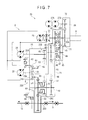
- FIG. 7 schematically illustrates a power transmission route in the transmission at a second forward gear or a second reverse gear.
- FIG. 8 schematically illustrates a power transmission route in the transmission at a third forward gear.
- FIG. 9 schematically illustrates a power transmission route in the transmission at a fourth forward gear.
- FIG. 10 is a flowchart showing an acceleration gear shifting process.
- FIG. 11 is a flowchart showing a deceleration gear shifting process.
- FIG. 1 is a transparent view schematically illustrating a wheel loader 1 according to an exemplary embodiment and a power transmission system thereof for traveling. It should be noted that directions of front, rear, right and left hereinafter mean directions of front, rear, right and left from an operator seated in a cab 6 shown in FIG. 1 .
- the wheel loader 1 is substantially the same as a typical wheel loader except, for instance, an arrangement of a transmission 20 (described later) and appearance.
- the wheel loader 1 includes: a vehicle body 2 including a front vehicle body and a rear vehicle body; and a bucket 3 , which is working equipment for excavation and loading, attached to a front side of the front vehicle body through a hydraulic working equipment drive mechanism 4 including, for instance, a boom, a bell crank, a connecting link, a bucket cylinder and a boom cylinder.
- the rear vehicle body includes a rear vehicle body frame 5 (shown by a two-dot chain line in FIG. 1 ) made of, for instance, a thick metal plate.
- the box-shaped cab 6 where an operator is to be seated is provided on a front upper portion of the rear vehicle body frame 5 .
- the transmission 20 is provided at a front lower portion of the rear vehicle body frame 5 .
- An engine compartment 7 is provided at a rear side of the rear vehicle body frame 5 .
- a power source i.e., a diesel engine (hereinafter, simply referred to as “engine”) 8 is mounted.
- engine 8 a diesel engine
- an axial direction of a crankshaft of the engine 8 is parallel with a front-rear direction of the vehicle body, and power from the engine 8 is outputted through a flywheel (not shown) provided at a front side of the engine 8 .
- the power outputted through the flywheel is inputted to the transmission 20 .
- a part of the power outputted from the transmission 20 is transmitted to a rear axle 11 through a rear drive shaft 9 and to rear wheels.
- Another part of the power outputted from the transmission 20 is transmitted to a front axle 13 through a front drive shaft 12 and to front wheels.
- FIG. 2 schematically illustrates a power transmission route in the transmission 20 .
- the transmission 20 is capable of switching between mechanical drive and hydraulic drive for transmitting the power inputted from the engine 8 to the drive shafts 9 , 12 .
- the transmission 20 thus includes a mechanical drive unit 21 that transmits the power through gear trains to the drive shafts 9 , 12 ; a hydraulic static transmission (HST) pump 22 (a hydraulic pump) that delivers a hydraulic oil for the hydraulic drive; first hydraulic motor 23 and second hydraulic motor 24 that are driven by the hydraulic oil delivered from the HST pump 22 ; and a hydraulic drive unit 25 that transmits power inputted from the first hydraulic motor 23 and the second hydraulic motor 24 to the drive shafts 9 , 12 through the gear trains.
- HST hydraulic static transmission
- the transmission 20 is configured to be shifted into first to fourth forward gears (low speed to high speed) and first to second reverse gears (low speed to high speed).
- the mechanical drive unit 21 is related to the third and fourth forward gears.
- HST power transmission using the HST pump 22 , the first hydraulic motor 23 , the second hydraulic motor 24 and the hydraulic drive unit 25 is related to the first and second forward gears and the first and second reverse gears.
- the flywheel (not shown) of the engine 8 is connected to an engine shaft 20 A of the transmission 20 .
- the mechanical drive unit 21 includes: a gear 41 rotatably supported by the engine shaft 20 A; a gear 42 attached to the engine shaft 20 A; a clutch 43 provided between the gears 41 , 42 ; an intermediate shaft 44 provided below the engine shaft 20 A; a gear 45 attached to the intermediate shaft 44 and meshing with the gear 41 ; a gear 46 rotatably supported by the intermediate shaft 44 and meshing with the gear 42 ; a clutch 47 provided between the gears 45 , 46 , a gear 48 similarly attached to the intermediate shaft 44 ; a combining shaft 49 provided below the intermediate shaft 44 ; a gear 51 attached to the combining shaft 49 and meshing with the gear 48 ; a first combining gear 52 similarly attached to the combining shaft 49 ; a second combining gear 53 provided adjacent to the first combining gear 52 ; a clutch 54 provided between the first combining gear 52 and the second combining gear 53 ; and a gear 55 attached to an output shaft 20 B and meshing with the first combining gear 52 .
- FIG. 2 shows that the gear 48 and the gear 51 are spaced from each other and the second combining gear 53 and a gear 66 (described later) are spaced from each other for a reason of drawing, these gears actually mesh with each other.
- the output shaft 20 B is provided with a multi-plate parking brake 56 .
- the clutches 43 , 47 of the mechanical drive unit 21 are multi-plate hydraulic wet clutches.
- the clutches 54 , 65 (described later) are also multi-plate hydraulic wet clutches.
- transmission/cutoff of the power in the mechanical drive unit 21 can be controlled by controlling engagement/disengagement of the clutches 43 , 47 .
- the clutches 43 , 47 thus define a mechanical drive clutch.
- the HST pump 22 is connected to the engine shaft 20 A along with an accessory pump 28 that delivers a hydraulic oil for driving the working equipment drive mechanism 4 .
- the HST pump 22 is a bidirectional swash-plate type variable displacement pump, in which a swash plate is inclinable to both of positive-angle side and negative-angle side with reference to a swash plate angle of zero degrees.
- a discharge direction of the hydraulic oil from the HST pump 22 changes and, consequently, rotation directions of the first hydraulic motor 23 and the second hydraulic motor 24 change depending on the swash plate angle, which is set positive or negative over or below zero degrees.
- the HST pump 22 functions as a hydraulic motor to adversely bias the engine 8 so that engine brake is applied.
- the hydraulic pump may be an angled-piston type pump.
- any variable displacement hydraulic pump is usable as long as displacement can be changed by controlling a swash plate angle or an angled piston angle.
- the first hydraulic motor 23 and the second hydraulic motor 24 which are angled-piston type variable displacement motors capable of bidirectional rotation, are juxtaposed to each other in a hydraulic circuit A including the HST pump 22 .
- the respective rotation directions of the first hydraulic motor 23 and the second hydraulic motor 24 can be switched by changing the discharge direction of the hydraulic oil from the HST pump 22 .
- the normal rotation of the first hydraulic motor 23 and the second hydraulic motor 24 makes the wheel loader 1 travel forward, whereas the inverse rotation makes the wheel loader 1 reverse.
- hydraulic motors may be swash-plate type motors.
- any variable displacement hydraulic motor is usable as long as displacement can be changed by controlling a swash plate angle or an angled piston angle.
- the hydraulic drive unit 25 includes: a first hydraulic drive unit 25 A that transmits power outputted from the first hydraulic motor 23 ; a second hydraulic drive unit 25 B that transmits power outputted from the second hydraulic motor 24 ; a power combining unit 25 C that combines the power transmitted through the first hydraulic drive unit 25 A and the power transmitted through the second hydraulic drive unit 25 B and outputs the combined power.
- the first hydraulic drive unit 25 A includes a planetary mechanism. Specifically, the first hydraulic drive unit 25 A includes: a sun gear 61 attached to an output shaft 23 A of the first hydraulic motor 23 ; a plurality of planetary gears 62 arranged around the sun gear 61 and meshing with the sun gear 61 ; a gear-shaped carrier 63 on which the planetary gears 62 are supported; a ring gear 64 disposed to surround outer circumferences of the planetary gears 62 and mesh with the planetary gears 62 , the ring gear 64 rotating coaxially with the output shaft 23 A; and a clutch 65 disposed between the ring gear 64 and a transmission casing (not shown).
- the second hydraulic drive unit 25 B includes: the gear 66 attached to an output shaft 24 A of the second hydraulic motor 24 ; the second combining gear 53 rotatably supported by the combining shaft 49 and meshing with the gear 66 ; and a clutch 54 disposed between the first combining gear 52 and the second combining gear 53 .
- the power combining unit 25 C includes: a first combining gear 52 that meshes with the carrier 63 to receive power transmitted from the first hydraulic drive unit 25 A and receives power transmitted from the second hydraulic drive unit 25 B when the clutch 54 is engaged; and a gear 55 that meshes with the first combining gear 52 .
- the clutches 54 , 65 are both engaged, the power from the first hydraulic motor 23 and the power from the second hydraulic motor 24 are combined by the first combining gear 52 .
- the combined power is transmitted from the first combining gear 52 to the output shaft 20 B through the gear 55 .
- transmission/cutoff of the power in the hydraulic drive unit 25 can be controlled by controlling engagement/disengagement of the clutches 54 , 65 .
- the clutches 54 , 65 thus define a hydraulic drive clutch.
- first combining gear 52 and the gear 55 are also components of the mechanical drive unit 21 in the exemplary embodiment.
- the power combining unit 25 C can thus not only combine the power from the first hydraulic motor 23 and the power from the second hydraulic motor 24 , but also combine the power from the mechanical drive unit 21 and the power from the hydraulic drive unit 25 .
- the transmission 20 includes a power take off (PTO) 26 disposed near a power input side (i.e., near the engine 8 ).
- PTO power take off
- the PTO 26 includes: a gear 71 attached to the engine shaft 20 A; a gear 72 that meshes with the gear 71 ; and a PTO shaft 26 A that is a rotary shaft attached with the gear 72 .
- the PTO shaft 26 A is connected to two hydraulic pumps 27 A, 27 B.
- the PTO 26 is in operation whenever the engine 8 is driven.
- the hydraulic pumps 27 A, 27 B are optional components and may thus be omitted. In this case, the PTO shaft 26 A rotates with substantially no load.
- Other device(s) may be connected to the PTO shaft 26 A in place of the hydraulic pumps 27 A, 27 B.
- the control circuit mainly includes a vehicle-body controller 100 and an engine controller 110 .
- the vehicle-body controller 100 is configured to communicate with the engine controller 110 .
- the vehicle-body controller 100 receives detection signals inputted from sensors provided to the wheel loader 1 , which include a motor speed sensor 114 , an HST pressure sensor 115 , a vehicle speed sensor 116 and a shift lever 117 .
- the engine controller 110 receives detection data outputted from an accelerator opening degree sensor 111 and an engine speed sensor 112 and controls a fuel injector 113 .
- the engine controller 110 is configured to communicate with the vehicle-body controller 100 .
- the accelerator opening degree sensor 111 detects an operation amount (accelerator opening degree) of an accelerator pedal that is provided in the cab 6 and operated by an operator and outputs the detected accelerator opening degree to the engine controller 110 .
- the engine speed sensor 112 detects an actual engine speed of the engine 8 and outputs the detected engine speed to the engine controller 110 .
- the fuel injector 113 employs a common rail fuel injection system including, for instance, a fuel pump, a common rail and an injector.
- the engine controller 110 controls the fuel injector 113 in accordance with the accelerator opening degree outputted from the accelerator opening degree sensor 111 to control an output torque and engine speed of the engine 8 .
- the motor speed sensor 114 which is a sensor for detecting respective rotation speeds of the output shafts 23 A, 24 A of the first hydraulic motor 23 and the second hydraulic motor 24 , outputs detected motor speed signals to the vehicle-body controller 100 .
- the motor speed sensor 114 may indirectly detect the respective rotation speeds of the output shafts 23 A, 24 A from, for instance, the swash plate angle of the HST pump 22 , the angled piston angles of the hydraulic motors 23 , 24 and the pressure of the hydraulic oil in the hydraulic circuit A instead of directly detecting the rotation speeds.
- the HST pressure sensor 115 which is provided in the hydraulic circuit A, detects the pressure of the hydraulic oil in the hydraulic circuit A and outputs a detected pressure signal to the vehicle-body controller 100 .
- the vehicle speed sensor 116 which is a sensor for detecting a vehicle speed from a rotation speed of a tire drive axle, outputs a detected vehicle speed signal to the vehicle-body controller 100 .
- the shift lever 117 is provided near a steering column in the cab 6 . An operator operates the shift lever 117 to switch forward and reverse gear positions. The switched gear position is electrically detected.
- the vehicle-body controller 100 When the first forward gear is selected using the shift lever 117 , the vehicle-body controller 100 maintains the first forward gear. Also when the second forward gear is selected, the vehicle-body controller 100 automatically switches between the first forward gear and the second forward gear in accordance with a load detected by a load detecting unit 101 as described later.
- the vehicle-body controller 100 When the third forward gear is selected using the shift lever 117 , the vehicle-body controller 100 automatically switches among the first to third forward gears in accordance with a load detected by the load detecting unit 101 .
- the vehicle-body controller 100 When the fourth forward gear is selected using the shift lever 117 , the vehicle-body controller 100 automatically switches among the first to fourth forward gears in accordance with a load detected by the load detecting unit 101 .
- shift lever 117 may be replaced by a lever for switching between forward and reverse travels and a shift control switch for setting a gear position.
- the vehicle-body controller 100 includes the load detecting unit 101 and a switching controlling unit 102 for controlling switching between the hydraulic drive and the mechanical drive.
- the vehicle-body controller 100 controls the engine 8 , the HST pump 22 , the first hydraulic motor 23 , the second hydraulic motor 24 and the clutches 43 , 47 , 54 , 65 based on output signals from the engine controller 110 , the sensors 114 , 115 , 116 and the shift lever 117 and the switching controlling unit 102 of the vehicle-body controller 100 as described later.
- the vehicle-body controller 100 controls, for instance, the output torque and engine speed of the engine 8 , the swash plate angle of the HST pump 22 , the angled piston angles of the hydraulic motors 23 , 24 and respective engagement conditions of the clutches 43 , 47 , 54 , 65 .
- the load detecting unit 101 detects the load on a wheel loader 1 .
- the load includes a running load and a working equipment load. Since the engine 8 is a power source for both of traveling and the working equipment, the load detecting unit 101 detects the load of traveling and the working equipment load collectively as the “load”.
- the load can be found based on the accelerator opening degree detected by the accelerator opening degree sensor 111 and the engine torque estimated from a fuel injection amount of the fuel injector 113 .
- the load detecting unit 101 thus calculates the load based on the accelerator opening degree and fuel injection amount data outputted from the engine controller 110 .
- the switching controlling unit 102 sets a switching vehicle speed (a switching point) with reference to a switching control map for setting conditions for switching between the hydraulic drive and the mechanical drive.
- the switching control map is made based on a characteristic diagram of FIG. 4 , which shows a relationship between tractive force and vehicle speed and a relationship between efficiency and vehicle speed.
- a line WL F1 denotes characteristics between tractive force and vehicle speed at the first forward gear
- a line WL F2 denotes characteristics between tractive force and vehicle speed at the second forward gear
- a line WL F3 denotes characteristics between tractive force and vehicle speed at the third forward gear
- a line WL F4 denotes characteristics between tractive force and vehicle speed at the fourth forward gear
- a line WL B1 denotes characteristics between tractive force and vehicle speed at the first reverse gear
- a line WL B2 denotes characteristics between tractive force and vehicle speed at the second reverse gear.
- a line VL F1 denotes characteristics between efficiency and vehicle speed at the first forward gear
- a line VL F2 denotes characteristics between efficiency and vehicle speed at the second forward gear
- a line VL F3 denotes characteristics between efficiency and vehicle speed at the third forward gear
- a line VL F4 denotes characteristics between efficiency and vehicle speed at the fourth forward gear
- a line VL B1 denotes characteristics between efficiency and vehicle speed at the first reverse gear
- a line VL B2 denotes characteristics between efficiency and vehicle speed at second reverse gear.
- the efficiency is a ratio of a tire output to an engine output.
- vehicle speeds available under the mechanical drive cover the maximum forward vehicle speed.
- vehicle speeds available under the mechanical drive overlap with vehicle speeds available under the hydraulic drive.
- a vehicle speed range of from 0 to 30 km/h may be covered at the first and second forward gears under the hydraulic drive
- a vehicle speed range of from 15 to 23 km/h may be covered at the third forward gear under the mechanical drive
- a vehicle speed range of from 21.5 to 38 km/h at the fourth forward gear under the mechanical drive is selectable either under the hydraulic drive or under the mechanical drive.
- the hydraulic drive may be switched to the mechanical drive.
- the switching controlling unit 102 sets the switching vehicle speed (the switching point).
- the switching controlling unit 102 sets the switching point with reference to the switching control map, i.e., a characteristic curve between a tractive force and vehicle speed (hereinafter, referred to as “tractive force curve”) at the second forward gear as shown in FIG. 5 .
- the line WL F2 in FIG. 4 is a maximum tractive force curve obtained when the accelerator opening degree is set at “large”.
- a plurality of tractive force curves can be obtained depending on the accelerator opening degree.
- five tractive force curves WL F2 , WL F2A , WL F2B , WL F2C and WL F2D are defined in descending order in terms of the accelerator opening degree.
- switching vehicle speeds (switching points) C 1 to C 5 at which the second forward gear (the hydraulic drive) can be switched to the third forward speed (the mechanical drive), are respectively defined in the tractive force curves WL F2 , WL F2A , WL F2B , WL F2C and WL F2D .
- the vehicle-body controller 100 selects one of the tractive force curves in accordance with the accelerator opening degree detected by the accelerator opening degree sensor 111 , and switches from the second forward gear (the hydraulic drive) to the third forward gear (the mechanical drive) when the vehicle speed detected by the vehicle speed sensor 116 reaches the vehicle speed of the switching point defined in the selected tractive force curve.
- the value of the switching point becomes smaller as the accelerator opening degree becomes smaller (the load becomes smaller), and becomes larger as the accelerator opening degree becomes larger.
- the smaller the load is, the earlier the gear position is switched to the third forward gear.
- the above setting is necessary for the following reasons.
- the accelerator opening degree becomes larger, the engine speed of the engine 8 becomes higher due to the necessity of a larger horsepower.
- the hydraulic drive should be switched to the mechanical drive at a vehicle speed as low as possible as described above.
- the maximum horsepower is required according to the maximum tractive force curve WL F2 , the engine speed of the engine 8 cannot be significantly reduced.
- the engine speed of the engine 8 obtained under the hydraulic drive immediately before the hydraulic drive is switched to the mechanical drive should not be significantly different from the engine speed of the engine 8 obtained immediately after the hydraulic drive is switched to the mechanical drive. Accordingly, on the maximum tractive force curve WL F2 , the vehicle speed under the hydraulic drive immediately before switching needs to be set relatively high so that the engine speed of the engine 8 is increased prior to switching to the mechanical drive.
- the engine speed of the engine 8 under the hydraulic drive can be kept low and thus a further increase in horsepower is available. Therefore, while the engine speed of the engine 8 is suppressed to be low, the vehicle speed can be increased by appropriately adjusting the swash plate angle of the HST pump 22 and the angled piston angle of the second hydraulic motor 24 . In this case, since the engine speed of the engine 8 can be suppressed to be low, switching to a lower vehicle speed can be performed while a difference between engine speeds before and after the switching is kept small.
- a lower limit is set to deal with a rapid change in the load.
- the switching points (the switching vehicle speeds or switching timings) C 1 to C 5 are defined on the tractive force curves WL F2 to WL F2D in accordance with the accelerator opening degree in view of the lower limit.
- the vehicle-body controller 100 selects one of the tractive force curves in accordance with the accelerator opening degree (i.e., load), and switches from the hydraulic drive to the mechanical drive when the vehicle speed of the switching point defined on the selected tractive force curve is reached.
- the accelerator opening degree i.e., load
- the engine torque under the mechanical drive is variable and the vehicle speed is only required to change along a tractive force curve substantially identical to a line defined for a case where the vehicle continuously travels under the hydraulic drive. Therefore, the torque produced by the engine 8 may be reduced to improve fuel efficiency.
- the switching controlling unit sets the switching point(s) with reference to the switching control map but may calculate the switching point(s). For instance, the switching point(s) (vehicle speed(s)) may be calculated by substituting the gear position and the accelerator opening degree (load) in a predetermined calculating formula. Alternatively, a calculating formula may be prepared for each of the gear positions to be selected, and the switching point may be calculated by substituting the accelerator opening degree (load) in the calculating formula for selected one of the gear positions.
- the first forward gear or the first reverse gear of the HST drive is usually selected due to a large running load.
- the second forward gear or the second reverse gear of the HST drive is selected.
- the third forward gear of the mechanical drive is selected.
- the forward fourth gear of the mechanical drive is selected.
- a reverse gear may be provided to allow the wheel loader 1 to reverse under the mechanical drive.
- the vehicle-body controller 100 disengages the clutches 43 , 47 of the mechanical drive unit 21 . Consequently, no power is transmitted through the mechanical drive unit 21 .
- the vehicle-body controller 100 engages the clutches 54 , 65 .
- the power from the first hydraulic motor 23 and the power from the second hydraulic motor 24 are inputted to the power combining unit 25 C through the first hydraulic drive unit 25 A and the second hydraulic drive unit 25 B to be combined, and then transmitted to the output shaft 20 B.
- the power is transmitted from the two hydraulic motors 23 , 24 .
- a large tractive force can be produced as shown by the line WL F1 and the line WL B1 in FIG. 4 .
- a low-speed operation requiring a large tractive force (e.g., excavation) can thus be performed as described above. It is not necessary to wastefully increase the engine speed as in a driving system using a torque converter that transmits a torque based on a rotation speed difference.
- the above hydraulic static transmission drive using the two hydraulic motors 23 , 24 can smoothly change the speed without any gear shift shock and thus improves efficiency.
- the HST pump 22 is a bidirectional hydraulic pump and the hydraulic motors 23 , 24 are capable of bidirectional rotation hydraulic motor, so that switching between forward travel and reverse travel can be smoothly performed.
- the vehicle-body controller 100 disengages the clutches 43 , 47 of the mechanical drive unit 21 and thus no power is transmitted through the mechanical drive unit 21 .
- the vehicle-body controller 100 engages the clutch 54 , disengages the clutch 65 of the first hydraulic motor 23 , and sets the angled piston angle of the first hydraulic motor 23 at zero degrees. Consequently, no output from the first hydraulic motor 23 is provided, and power transmission from the first combining gear 52 to the first hydraulic motor 23 is inhibited. The power from the second hydraulic motor 24 is thus reliably transmitted to the output shaft 20 B.
- the power transmission according to the exemplary embodiment is a continuously variable transmission, so that the vehicle speed can be smoothly changed without any gear shift shock and switching between forward travel and reverse travel can be smoothly performed.
- the wheel loader 1 can thus work while traveling (e.g., transportation of soil and sand and snow removal).
- the hydraulic drive should preferably be switched to the mechanical drive as soon as possible.
- engine brake is applied, for instance, when the engine speed of the engine 8 is rapidly reduced or the vehicle rolls down a steep slope.
- the power transmitted from the tires exceeds the power outputted from the hydraulic drive unit 25 , so that the first hydraulic motor 23 and the second hydraulic motor 24 , which are in conjunction with each other through the clutches 54 , 65 , are adversely biased with an increased speed to function as hydraulic pumps.
- the inlet side of the HST pump 22 receives the inflow of a hydraulic oil with a higher pressure than a hydraulic oil at the outlet side, so that the HST pump 22 functions as a hydraulic motor.
- the engine 8 is thus adversely biased by the HST pump 22 to apply engine brake.
- a vehicle speed range where the vehicle can travel under the hydraulic drive covers a range where the vehicle works while traveling forward and a range where the vehicle reverses.
- the reverse vehicle speed range is not necessarily equal to or more than the forward vehicle speed range under the hydraulic drive, and is approximately not more than 30 km/h in the exemplary embodiment.
- the vehicle-body controller 100 disengages the clutches 54 , 65 . Further, the vehicle-body controller 100 sets the swash plate angle of the HST pump 22 and the angled piston angles of the hydraulic motors 23 , 24 at zero degrees. No power generated by the HST drive is thus transmitted to the output shaft 20 B.
- the vehicle-body controller 100 engages the clutch 47 of the mechanical drive unit 21 while disengaging the clutch 43 .
- the gear 41 since the gear 41 does not rotate, the power inputted to the engine shaft 20 A is transmitted from the gear 42 to the gear 46 , from the gear 46 to the gear 45 through the clutch 47 and further to the gear 48 through the intermediate shaft 44 .
- the power is then transmitted from the gear 48 to the first combining gear 52 through the gear 51 and the combining shaft 49 , from the first combining gear 52 to the gear 55 , and further to the output shaft 20 B. Since the clutch 43 is disengaged, the gear 41 , which meshes with the gear 45 , spins around the engine shaft 20 A.
- the third forward gear of the mechanical drive When the third forward gear of the mechanical drive is selected, efficiency can be improved with a certain amount of tractive force being ensured as shown by the line WL F3 , the line WL B3 , the line VL F3 and the line VL B3 in FIG. 4 . Accordingly, for instance, when the vehicle is unloaded and travels with a large running load (e.g., traveling up a slope), the third forward gear of the mechanical drive is selected.
- a large running load e.g., traveling up a slope
- the vehicle-body controller 100 keeps the clutches 54 , 65 disengaged and keeps the swash plate angle of the HST pump 22 and the angled piston angle of each of the hydraulic motors 23 , 24 at zero degrees in the same manner as when the third forward gear is selected.
- the vehicle-body controller 100 engages the clutch 43 of the mechanical drive unit 21 while disengaging the clutch 47 .
- the power inputted to the engine shaft 20 A is transmitted from the gear 42 to the gear 41 through the clutch 43 , from the gear 41 to the gear 45 and further to the gear 48 through the intermediate shaft 44 .
- the power is further transmitted in the same manner as when the third forward gear is selected. Since the clutch 47 is disengaged, the gear 46 , which meshes with the gear 42 , spins around the intermediate shaft 44 .
- the tractive force becomes smaller than one obtained when the third forward gear is selected, but efficiency can be improved as shown by the line WL F4 , the line WL B4 , the line VL F4 and the line VL B4 in FIG. 4 . Accordingly, for instance, when the vehicle is unloaded and travels with a small running load (e.g., traveling on a flat ground), the fourth forward gear of the mechanical drive is selected.
- a small running load e.g., traveling on a flat ground
- the HST pump 22 is driven.
- the swash plate angle of the swash-plate type HST pump 22 is set at zero degrees not to discharge the hydraulic oil. The displacement of the HST pump 22 is thus controlled to be zero so that the HST pump 22 is driven with substantially no load. Consequently, the power consumption of the HST pump 22 is sufficiently reduced to be ignored.
- the first hydraulic motor 23 While the planetary gear 62 , which meshes with the first combining gear 52 , rotates, the first hydraulic motor 23 is prevented from being adversely biased by a sufficiently large loss torque due to friction caused when the angled piston angle of the first hydraulic motor 23 is set at zero degrees. The first hydraulic motor 23 is thus in a state as if it were connected to a fixed clutch. The ring gear 64 thus does not rotate at a rotation speed corresponding to the planetary gear ratio and, consequently, the rotation of the first combining gear 52 caused by the mechanical drive unit 21 is not transmitted to the output shaft 23 A of the first hydraulic motor 23 .
- the clutch 65 when the clutch 65 is not disengaged, the rotation of the first combining gear 52 may be unexpectedly accelerated by the planetary mechanism to adversely bias the first hydraulic motor 23 at an excessively high speed. Accordingly, also in terms of the durability of the first hydraulic motor 23 , it is preferable that the clutch 65 is disengaged while the angled piston angle is set at zero degrees.
- the displacement of each of the hydraulic motors 23 , 24 may not be set at zero.
- the swash plate angle of the HST pump 22 and the angled piston angle of each of the hydraulic motors 23 , 24 are preferably set at zero to control the displacement thereof to be zero as in the exemplary embodiment in terms of prevention of wasteful power consumption.
- the speed for switching from the hydraulic drive to the mechanical drive is preferably reduced as much as possible in order to improve fuel efficiency.
- the vehicle-body controller 100 shifts the first forward gear set using the two hydraulic motors 23 , 24 to the second forward gear set only using the second hydraulic motor 24 in accordance with the accelerator opening degree detected by the accelerator opening degree sensor 111 (step S 1 ).
- the switching controlling unit 102 of the vehicle-body controller 100 selects one of the tractive force curves WL F2 to WL F2D stored in the switching control map in accordance with the accelerator opening degree detected by the accelerator opening degree sensor 111 (step S 2 ).
- the vehicle-body controller 100 performs a clutch operation for engaging the clutch 47 and disengaging the clutch 54 when the vehicle speed detected by the vehicle speed sensor 116 reaches the switching point defined on the selected tractive force curve to switch from the hydraulic drive (the second forward gear) to the mechanical drive (the third forward gear) (step S 3 ).
- the vehicle-body controller 100 performs a clutch operation for engaging the clutch 43 and disengaging the clutch 47 when determining that a running load is small (e.g., the vehicle travels on a flat ground without a load thereon) based on the accelerator opening degree and the running load to switch to the fourth forward gear of the mechanical drive (step S 4 ).
- a running load e.g., the vehicle travels on a flat ground without a load thereon
- step S 5 The acceleration gear shifting process is thus completed (step S 5 ).
- the switching point (switching vehicle speed) can be set high to increase the engine speed under the mechanical drive when a load is large (an accelerator opening degree is large) and the engine speed under the hydraulic drive is high.
- the exemplary embodiment thus allows for a relatively small difference between engine speeds before and after the switching. Consequently, the hydraulic drive can be smoothly switched to the mechanical drive with a reduced switching shock resulting from gear shift, thereby preventing a load in the bucket 3 from falling off.
- the switching point (switching vehicle speed) can be set low to reduce the engine speed under the mechanical drive when a load is small (an accelerator opening degree is small) and the engine speed under the hydraulic drive is low.
- the exemplary embodiment thus allows for a relatively small difference between engine speeds before and after the switching so that a switching shock resulting from gear shift can be reduced. Consequently, the hydraulic drive can be smoothly switched to the mechanical drive, thereby preventing a load in the bucket 3 from falling off. Further, the hydraulic drive can be switched to the mechanical drive early, thereby improving efficiency and reducing fuel consumption.
- the vehicle-body controller 100 In order to engage/disengage the clutch(es) as smoothly as possible to switch from the hydraulic drive to the mechanical drive and, consequently, to further reduce a gear shift shock, the vehicle-body controller 100 preferably should collaterally take the following measures
- the vehicle-body controller 100 adjusts the swash plate angle of the HST pump 22 and the angled piston angle of the second hydraulic motor 24 to increase the vehicle speed while further reducing the engine speed of the engine 8 .
- the swash plate angle is adjusted to increase the displacement of the HST pump 22 and/or the angled piston angle is adjusted to reduce the displacement of the second hydraulic motor 24 , thereby increasing the vehicle speed while reducing the engine speed of the engine 8 .
- at least one of the adjustment for increasing the displacement of the HST pump 22 and the adjustment for reducing the displacement of the second hydraulic motor 24 may be performed.
- the vehicle speed and the engine speed of the engine 8 are linearly proportional to each other. Accordingly, the engine speed at the third forward gear at the switching point (switching vehicle speed) of one of the tractive curves selected in accordance with a load is obtained, and the engine speed of the engine 8 under the hydraulic drive is controlled to be close to the obtained engine speed, thereby further reducing a difference in the engine speed of the engine 8 resulting from switching from the hydraulic drive to the mechanical drive and, consequently, further reducing a gear shift shock.
- a gear shift shock may be caused due to a rapid rise in torque.
- a torque reducing control is performed during the gear shifting process to reduce a gear shift shock.
- the vehicle-body controller 100 sends a command to the engine controller 110 to adjust the timing and/or the amount of fuel injection during the process for switching from the hydraulic drive to the mechanical drive, and the engine controller 110 adjusts the injection amount of the fuel injector 113 in accordance with the command.
- Torque generated when the hydraulic drive is switched to the mechanical drive can thus be reduced and, consequently, a gear shift shock is further reduced.
- the clutches 43 , 47 , 54 , 65 of the exemplary embodiment are each in the form of a modulation clutch having a modulation pattern for reducing a shock to absorb a difference between the rotation speeds on the upstream and downstream of the clutch.
- the modulation clutch is configured not only to be simply engaged (engagement ratio: 100%) and disengaged (engagement ratio: 0%) but also to slide (i.e., the engagement ratio can be adjusted to an interim value between 100% to 0% to adjust a transmission amount of the engine output).
- the engagement ratio of the modulation clutch can be adjusted by a plurality of processes. In the exemplary embodiment, the engagement ratio is determined based on a controlling hydraulic pressure applied to the clutch.
- the vehicle-body controller 100 controls the controlling hydraulic pressure based on a variation pattern defined as the modulation pattern, so that the clutch is temporarily set in a so-called semi-clutch state (an interim value of the engagement ratio) to reduce a gear shift shock.
- the vehicle-body controller 100 In switching from the mechanical drive to the hydraulic drive, the vehicle-body controller 100 starts moving the angled piston of the second hydraulic motor 24 and the swash plate of the HST pump 22 before the clutch 54 is engaged. Specifically, the vehicle-body controller 100 sets the swash plate angle of the HST pump 22 to an angle corresponding to the engine speed of the engine 8 , and adjusts the angled piston angle of the second hydraulic motor 24 so that the motor speed of the second hydraulic motor 24 corresponds to the resulting flow rate and vehicle speed (step S 11 ).
- the vehicle-body controller 100 engages the clutch 54 when the motor speed of the second hydraulic motor 24 is increased and a difference between the rotation speed of the first combining gear 52 and the rotation speed of the second combining gear 53 disposed on the upstream and downstream of the clutch 54 reaches a threshold or less (step S 12 ).
- the power transmitted through the mechanical drive unit 21 and the power transmitted from the second hydraulic motor 24 through the second hydraulic drive unit 25 B are thus temporarily combined by the power combining unit 25 C and transmitted to the output shaft 20 B.
- the vehicle-body controller 100 then disengages the clutch 47 of the mechanical drive unit 21 when the pressure of the hydraulic circuit A detected by the HST pressure sensor 115 increases to exceed a threshold (step S 13 ).
- step S 14 The deceleration gear shifting process for switching from the mechanical drive to the hydraulic drive is thus completed (step S 14 ).
- the motor speed is 0 rpm (a stopped state).
- the engine speed of the engine 8 changes in accordance with the vehicle speed, and may be set approximately in a range from 1200 to 1400 rpm.
- the clutch 54 may be engaged with the second hydraulic motor 24 being in the stopped state.
- the clutch 54 should preferably be engaged after the motor speed of the second hydraulic motor 24 is increased to a certain level. In this case, a difference between motor speeds before and after the switching can be reduced and, consequently, the mechanical drive can be smoothly switched to the hydraulic drive.
- the mechanical drive is switched to the hydraulic drive via a combination of the mechanical drive and the hydraulic drive.
- the mechanical drive can thus be smoothly switched to the hydraulic drive with a reduced switching shock during the deceleration process, thereby preventing a load in the bucket 3 from falling off during the deceleration process.
- the exemplary embodiment employs the two hydraulic motors, i.e., the first hydraulic motor 23 and the second hydraulic motor 24 , a single hydraulic motor for traveling may be employed without departing from the scope of the invention. Alternatively, three or more hydraulic motors for traveling may be employed without departing from the scope of the invention.
- the mechanical drive unit 21 includes the clutches 43 , 47 to switch between two gear positions, i.e., the third forward gear and the fourth forward gear, three or more switchable gear positions may be provided or merely a single gear position is provided.
- the load of the wheel loader 1 (including work load and running load) is detected as an accelerator opening degree and the switching point (switching timing) for switching between the hydraulic drive and the mechanical drive is adjusted in accordance with the accelerator opening degree and the vehicle speed.
- the load of the wheel loader 1 may be detected using other parameter(s) such as the fuel injection amount of the engine 8 .
- the mechanical drive unit 21 may include: two gears fixed to the engine shaft 20 A; another two gears that individually mesh with the two gears and are rotatably supported by the intermediate shaft 44 ; and a clutch provided to a single gear fixed to the intermediate shaft 44 .
- a gear of the mechanical drive unit 21 and a gear of the hydraulic drive unit 25 may be individually fixed to the output shaft 20 B, and the mechanical drive unit 21 and the hydraulic drive unit 25 may be independent of each other.
- the power transmitted through the first hydraulic drive unit 25 A and the power transmitted through the second hydraulic drive unit 25 B may be combined at the gear 55 fixed to the output shaft 20 B.
- the gear arrangement of the transmission 20 may be determined in view of, for instance, the sizes and layouts of the wheel loader 1 , the engine 8 , the HST pump 22 and the hydraulic motors 23 , 24 .
Landscapes
- Engineering & Computer Science (AREA)
- General Engineering & Computer Science (AREA)
- Mechanical Engineering (AREA)
- Mining & Mineral Resources (AREA)
- Civil Engineering (AREA)
- Structural Engineering (AREA)
- Control Of Transmission Device (AREA)
- Control Of Fluid Gearings (AREA)
- Operation Control Of Excavators (AREA)
Abstract
Description
Claims (11)
Applications Claiming Priority (3)
| Application Number | Priority Date | Filing Date | Title |
|---|---|---|---|
| JP2013093854A JP6170719B2 (en) | 2013-04-26 | 2013-04-26 | Wheel loader |
| JP2013-093854 | 2013-04-26 | ||
| PCT/JP2014/059781 WO2014175026A1 (en) | 2013-04-26 | 2014-04-02 | Wheel loader |
Publications (2)
| Publication Number | Publication Date |
|---|---|
| US20160024755A1 US20160024755A1 (en) | 2016-01-28 |
| US9416519B2 true US9416519B2 (en) | 2016-08-16 |
Family
ID=51791607
Family Applications (1)
| Application Number | Title | Priority Date | Filing Date |
|---|---|---|---|
| US14/781,842 Expired - Fee Related US9416519B2 (en) | 2013-04-26 | 2014-04-02 | Wheel loader |
Country Status (5)
| Country | Link |
|---|---|
| US (1) | US9416519B2 (en) |
| EP (1) | EP2990691B1 (en) |
| JP (1) | JP6170719B2 (en) |
| CN (1) | CN105074280B (en) |
| WO (1) | WO2014175026A1 (en) |
Families Citing this family (23)
| Publication number | Priority date | Publication date | Assignee | Title |
|---|---|---|---|---|
| EP3154809B1 (en) | 2014-06-10 | 2022-08-24 | Danfoss Power Solutions II Technology A/S | Energy recovery system for off-highway vehicles with hydraulic transformer coupled to transmission power take-off |
| DE112014000167B4 (en) * | 2014-09-19 | 2017-03-16 | Komatsu Ltd. | Work vehicle and control method for a work vehicle |
| CN104709838B (en) * | 2015-02-07 | 2017-03-08 | 浙江双鸟机械有限公司 | A kind of calabash load limiter debugging apparatus |
| US9605756B1 (en) | 2015-12-08 | 2017-03-28 | Caterpillar Inc. | Hybrid hydrostatic-direct drive transmission |
| JP6986832B2 (en) * | 2016-08-26 | 2021-12-22 | 株式会社小松製作所 | Wheel loader and wheel loader control method |
| EP3609751A1 (en) * | 2017-04-11 | 2020-02-19 | Dana Italia S.r.L. | A hydraulic circuit for an adaptive park braking system and method of operation thereof |
| US10891974B1 (en) | 2017-06-07 | 2021-01-12 | Sandisk Technologies Llc | Magnetic head with current assisted magnetic recording and method of making thereof |
| US10896690B1 (en) | 2017-06-07 | 2021-01-19 | Sandisk Technologies Llc | Magnetic head with current assisted magnetic recording and method of making thereof |
| DE102017211232A1 (en) * | 2017-07-03 | 2019-01-03 | Robert Bosch Gmbh | Travel drive and method for driving a traction drive |
| DE102017212921A1 (en) * | 2017-07-27 | 2019-01-31 | Robert Bosch Gmbh | Variable Displacement hydraulic machine, gearbox assembly with hydraulic machine, and method of controlling gearbox assembly |
| JP6946211B2 (en) | 2018-02-22 | 2021-10-06 | 株式会社小松製作所 | Transmission and work vehicle control system |
| JP6924159B2 (en) | 2018-02-23 | 2021-08-25 | 株式会社小松製作所 | Work vehicle and control method of work vehicle |
| JP6736597B2 (en) * | 2018-03-28 | 2020-08-05 | 日立建機株式会社 | Wheel loader |
| US10839844B1 (en) | 2018-06-18 | 2020-11-17 | Western Digital Technologies, Inc. | Current-assisted magnetic recording write head with wide conductive element in the write gap |
| US11017801B1 (en) | 2018-10-09 | 2021-05-25 | Western Digital Technologies, Inc. | Magnetic head with assisted magnetic recording and method of making thereof |
| US10891975B1 (en) | 2018-10-09 | 2021-01-12 | SanDiskTechnologies LLC. | Magnetic head with assisted magnetic recording and method of making thereof |
| JP7245582B2 (en) * | 2018-11-16 | 2023-03-24 | 株式会社小松製作所 | WORK VEHICLE AND CONTROL METHOD FOR WORK VEHICLE |
| JP7141974B2 (en) * | 2019-03-25 | 2022-09-26 | 日立建機株式会社 | wheel loader |
| JP6961643B2 (en) * | 2019-03-29 | 2021-11-05 | 日立建機株式会社 | Wheel type work vehicle |
| CN111561017B (en) * | 2020-05-28 | 2022-06-07 | 三一重机有限公司 | Power system and excavator |
| EP4102105B1 (en) * | 2020-09-29 | 2025-08-13 | Hitachi Construction Machinery Co., Ltd. | Power transmitting device for vehicle |
| CN115234626B (en) * | 2022-07-04 | 2024-06-18 | 潍柴动力股份有限公司 | Mechanical hydraulic power split type continuously variable transmission system |
| JP7774545B2 (en) * | 2022-11-17 | 2025-11-21 | 株式会社クボタ | Continuously variable speed power transmission device for work vehicle and work vehicle |
Citations (13)
| Publication number | Priority date | Publication date | Assignee | Title |
|---|---|---|---|---|
| US3470769A (en) * | 1967-10-16 | 1969-10-07 | Gen Motors Corp | Input-split-power,output-split-power,compound-split-power,power train |
| JPH0238745A (en) | 1988-07-28 | 1990-02-08 | Komatsu Ltd | Mechanical/hydraulic type transmission gear and its control method |
| JPH02195062A (en) | 1988-05-31 | 1990-08-01 | Komatsu Ltd | Mechanical-hydraulic transmission and control method thereof |
| JPH0361755A (en) | 1989-07-27 | 1991-03-18 | Komatsu Ltd | Mechanical/hydraulic transmission device and control method thereof |
| US5193416A (en) | 1988-05-31 | 1993-03-16 | Kabushiki Kaisha Komatsu Seisakusho | Mechanical-hydraulic transmission gear system and method of controlling power transmission using the system |
| JP2000130558A (en) | 1998-10-27 | 2000-05-12 | Yanmar Diesel Engine Co Ltd | Hst control method for hydro-mechanical transmission |
| JP2003185016A (en) | 2001-12-19 | 2003-07-03 | Yanmar Agricult Equip Co Ltd | Hydraulic continuously variable transmission |
| US6616559B1 (en) | 1998-10-26 | 2003-09-09 | Yanmar Co., Ltd. | Continuously variable transmission |
| JP2004144254A (en) | 2002-10-28 | 2004-05-20 | Komatsu Ltd | Hydraulic drive vehicle |
| US7070531B2 (en) * | 2003-05-27 | 2006-07-04 | Komatsu Ltd. | Hydromechanical transmission |
| US7195580B2 (en) * | 2003-11-11 | 2007-03-27 | Komatsu Ltd. | Vehicle control system |
| US7361111B2 (en) * | 2004-08-10 | 2008-04-22 | Hofer Forschungs Und Entwicklungs & Co. Kg | Power branching transmission for motor vehicles |
| US20080275612A1 (en) | 2005-12-03 | 2008-11-06 | Zf Friedrichshafen Ag | Shift Control Method for an Automatic Gearbox |
Family Cites Families (1)
| Publication number | Priority date | Publication date | Assignee | Title |
|---|---|---|---|---|
| JP3408622B2 (en) * | 1994-04-14 | 2003-05-19 | 株式会社小松製作所 | Hydraulic retarder transmission method for power transmission device |
-
2013
- 2013-04-26 JP JP2013093854A patent/JP6170719B2/en not_active Expired - Fee Related
-
2014
- 2014-04-02 EP EP14787403.6A patent/EP2990691B1/en not_active Not-in-force
- 2014-04-02 CN CN201480017515.0A patent/CN105074280B/en not_active Expired - Fee Related
- 2014-04-02 WO PCT/JP2014/059781 patent/WO2014175026A1/en not_active Ceased
- 2014-04-02 US US14/781,842 patent/US9416519B2/en not_active Expired - Fee Related
Patent Citations (15)
| Publication number | Priority date | Publication date | Assignee | Title |
|---|---|---|---|---|
| US3470769A (en) * | 1967-10-16 | 1969-10-07 | Gen Motors Corp | Input-split-power,output-split-power,compound-split-power,power train |
| JPH02195062A (en) | 1988-05-31 | 1990-08-01 | Komatsu Ltd | Mechanical-hydraulic transmission and control method thereof |
| US5193416A (en) | 1988-05-31 | 1993-03-16 | Kabushiki Kaisha Komatsu Seisakusho | Mechanical-hydraulic transmission gear system and method of controlling power transmission using the system |
| JPH0238745A (en) | 1988-07-28 | 1990-02-08 | Komatsu Ltd | Mechanical/hydraulic type transmission gear and its control method |
| JPH0361755A (en) | 1989-07-27 | 1991-03-18 | Komatsu Ltd | Mechanical/hydraulic transmission device and control method thereof |
| US6616559B1 (en) | 1998-10-26 | 2003-09-09 | Yanmar Co., Ltd. | Continuously variable transmission |
| JP2000130558A (en) | 1998-10-27 | 2000-05-12 | Yanmar Diesel Engine Co Ltd | Hst control method for hydro-mechanical transmission |
| JP2003185016A (en) | 2001-12-19 | 2003-07-03 | Yanmar Agricult Equip Co Ltd | Hydraulic continuously variable transmission |
| JP2004144254A (en) | 2002-10-28 | 2004-05-20 | Komatsu Ltd | Hydraulic drive vehicle |
| US20040211614A1 (en) | 2002-10-28 | 2004-10-28 | Nobuo Matsuyama | Hydraulically driven vehicle |
| US7070531B2 (en) * | 2003-05-27 | 2006-07-04 | Komatsu Ltd. | Hydromechanical transmission |
| US7195580B2 (en) * | 2003-11-11 | 2007-03-27 | Komatsu Ltd. | Vehicle control system |
| US7361111B2 (en) * | 2004-08-10 | 2008-04-22 | Hofer Forschungs Und Entwicklungs & Co. Kg | Power branching transmission for motor vehicles |
| US20080275612A1 (en) | 2005-12-03 | 2008-11-06 | Zf Friedrichshafen Ag | Shift Control Method for an Automatic Gearbox |
| JP2009518567A (en) | 2005-12-03 | 2009-05-07 | ツェットエフ フリードリヒスハーフェン アクチエンゲゼルシャフト | Shift change control method for automatic transmission for motor vehicle |
Non-Patent Citations (1)
| Title |
|---|
| International Search Report dated Jul. 1, 2015 for corresponding International Patent Application No. PCT/JP2014/059781, including English translation, 4 pages. |
Also Published As
| Publication number | Publication date |
|---|---|
| CN105074280B (en) | 2017-05-31 |
| JP2014214829A (en) | 2014-11-17 |
| CN105074280A (en) | 2015-11-18 |
| JP6170719B2 (en) | 2017-07-26 |
| EP2990691A4 (en) | 2017-06-14 |
| WO2014175026A1 (en) | 2014-10-30 |
| EP2990691A1 (en) | 2016-03-02 |
| EP2990691B1 (en) | 2018-09-05 |
| US20160024755A1 (en) | 2016-01-28 |
Similar Documents
| Publication | Publication Date | Title |
|---|---|---|
| US9416519B2 (en) | Wheel loader | |
| JP5694769B2 (en) | CVT control system with variable power source speed | |
| US8277364B2 (en) | Clutch control device for hydraulically driven vehicle | |
| CN101002010B (en) | Load control device for engine of work vehicle | |
| US8777808B2 (en) | Working vehicle control apparatus | |
| US8655557B2 (en) | Motor control device for working vehicle | |
| CN103429875B (en) | The driving-controlling device of working truck | |
| US8744695B2 (en) | Fuel consumption saving control device for work vehicle and fuel consumption saving method for work vehicle | |
| JP5996314B2 (en) | Wheel loader and wheel loader engine control method | |
| JP4648407B2 (en) | Construction vehicle | |
| US9695575B2 (en) | Work vehicle and method of controlling same | |
| WO2010109972A1 (en) | Construction vehicle | |
| US20160083931A1 (en) | Work vehicle and method of controlling work vehicle | |
| CN105612369A (en) | Work vehicle, and work vehicle control method | |
| US20200087892A1 (en) | Work vehicle | |
| JP4912249B2 (en) | Work vehicle | |
| US11027733B2 (en) | Vehicle speed control system | |
| CN111824156A (en) | Travel drive system for work machine | |
| CN105190120B (en) | The control method of working truck and working truck | |
| CN115190950B (en) | Power transmission device for vehicle | |
| US8499657B2 (en) | Transmission for work vehicle | |
| US20160186857A1 (en) | Method of controlling machines with continuously variable transmission | |
| CN117098935A (en) | Vehicle power transmission device | |
| JP4962957B2 (en) | Work vehicle | |
| CN113795630A (en) | Work vehicle and work vehicle control method |
Legal Events
| Date | Code | Title | Description |
|---|---|---|---|
| AS | Assignment |
Owner name: KOMATSU LTD., JAPAN Free format text: ASSIGNMENT OF ASSIGNORS INTEREST;ASSIGNOR:KOBIKI, YASUHIRO;REEL/FRAME:036716/0688 Effective date: 20150723 |
|
| ZAAA | Notice of allowance and fees due |
Free format text: ORIGINAL CODE: NOA |
|
| ZAAB | Notice of allowance mailed |
Free format text: ORIGINAL CODE: MN/=. |
|
| STCF | Information on status: patent grant |
Free format text: PATENTED CASE |
|
| MAFP | Maintenance fee payment |
Free format text: PAYMENT OF MAINTENANCE FEE, 4TH YEAR, LARGE ENTITY (ORIGINAL EVENT CODE: M1551); ENTITY STATUS OF PATENT OWNER: LARGE ENTITY Year of fee payment: 4 |
|
| FEPP | Fee payment procedure |
Free format text: MAINTENANCE FEE REMINDER MAILED (ORIGINAL EVENT CODE: REM.); ENTITY STATUS OF PATENT OWNER: LARGE ENTITY |
|
| LAPS | Lapse for failure to pay maintenance fees |
Free format text: PATENT EXPIRED FOR FAILURE TO PAY MAINTENANCE FEES (ORIGINAL EVENT CODE: EXP.); ENTITY STATUS OF PATENT OWNER: LARGE ENTITY |
|
| STCH | Information on status: patent discontinuation |
Free format text: PATENT EXPIRED DUE TO NONPAYMENT OF MAINTENANCE FEES UNDER 37 CFR 1.362 |
|
| FP | Lapsed due to failure to pay maintenance fee |
Effective date: 20240816 |