US9413304B2 - Electronic device and control method thereof - Google Patents
Electronic device and control method thereof Download PDFInfo
- Publication number
- US9413304B2 US9413304B2 US14/139,907 US201314139907A US9413304B2 US 9413304 B2 US9413304 B2 US 9413304B2 US 201314139907 A US201314139907 A US 201314139907A US 9413304 B2 US9413304 B2 US 9413304B2
- Authority
- US
- United States
- Prior art keywords
- voltage
- supply
- vacuum tube
- heater
- amplifier
- Prior art date
- Legal status (The legal status is an assumption and is not a legal conclusion. Google has not performed a legal analysis and makes no representation as to the accuracy of the status listed.)
- Expired - Fee Related, expires
Links
Images


Classifications
-
- H—ELECTRICITY
- H03—ELECTRONIC CIRCUITRY
- H03G—CONTROL OF AMPLIFICATION
- H03G5/00—Tone control or bandwidth control in amplifiers
- H03G5/02—Manually-operated control
- H03G5/04—Manually-operated control in untuned amplifiers
- H03G5/06—Manually-operated control in untuned amplifiers having discharge tubes
-
- H—ELECTRICITY
- H03—ELECTRONIC CIRCUITRY
- H03F—AMPLIFIERS
- H03F3/00—Amplifiers with only discharge tubes or only semiconductor devices as amplifying elements
- H03F3/02—Amplifiers with only discharge tubes or only semiconductor devices as amplifying elements with tubes only
-
- H—ELECTRICITY
- H03—ELECTRONIC CIRCUITRY
- H03F—AMPLIFIERS
- H03F3/00—Amplifiers with only discharge tubes or only semiconductor devices as amplifying elements
- H03F3/181—Low-frequency amplifiers, e.g. audio preamplifiers
-
- H—ELECTRICITY
- H03—ELECTRONIC CIRCUITRY
- H03F—AMPLIFIERS
- H03F3/00—Amplifiers with only discharge tubes or only semiconductor devices as amplifying elements
- H03F3/20—Power amplifiers, e.g. Class B amplifiers, Class C amplifiers
-
- H—ELECTRICITY
- H03—ELECTRONIC CIRCUITRY
- H03F—AMPLIFIERS
- H03F5/00—Amplifiers with both discharge tubes and semiconductor devices as amplifying elements
Definitions
- Apparatuses and methods consistent with exemplary embodiments relate to an electronic device and a control method thereof, and more particularly to an electronic device which can rapidly preheat a vacuum tube in an initial operation of the electronic device for rapid use of a vacuum tube audio amplifier, and a control method thereof.
- a vacuum tube audio amplifier includes a heater which preheats a vacuum tube without using an additional circuit, which takes relatively long time for a general user.
- One or more exemplary embodiments may provide an electronic device which allows a user to rapidly preheat a vacuum tube in an initial operation of an electronic device for rapid use of a vacuum tube audio amplifier, and a control method thereof.
- an electronic device including: an amplifier which is configured to amplify a sound signal and includes a vacuum tube including a heater configured to heat the vacuum tube; a voltage supply which is configured to supply a first voltage and a second voltage which is higher than the first voltage; and a controller which controls the voltage supply to supply the second voltage to the heater when supply of a drive voltage to the amplifier is started and to supply the first voltage to the heater if the vacuum tube reaches a predetermined temperature.
- the electronic device further may include a switch which selectively applies voltage, wherein the controller is configured to control the switch to perform switching for supply of a standby voltage to the vacuum tube when the amplifier enters a standby state and for supply of the first voltage or the second voltage to the vacuum tube when the supply of the drive voltage to the amplifier is restarted.
- the vacuum tube may include a temperature sensor configured to sense a temperature of the vacuum tube, and wherein the controller controls the voltage supply to supply the first voltage or the second voltage to the heater based on the temperature of the vacuum tube detected by the temperature sensor.
- a control method of an electronic device including: supplying a drive voltage to an amplifier which includes a vacuum tube provided with a heater; supplying a second voltage which is higher than a first voltage to the heater of the vacuum tube; and supplying the first voltage to the heater if the vacuum tube reaches a predetermined temperature.
- the method further may include supplying a standby voltage to the vacuum tube when the supply of the drive voltage to the amplifier is cut off and the amplifier enters a standby state, and supplying the first voltage or the second voltage to the vacuum tube when the supply of the drive voltage to the amplifier is restarted.
- the method further may include supplying the first voltage or the second voltage to the heater based on the temperature of the vacuum tube.
- FIG. 1 is a block diagram illustrating a configuration of an electronic device according to an exemplary embodiment
- FIG. 2 is a schematic circuit diagram illustrating a process of supplying a second voltage to preheat a vacuum tube of an electronic device, according to an exemplary embodiment
- FIG. 3 is a block diagram illustrating a configuration of an electronic device according to an exemplary embodiment
- FIG. 4 is a schematic circuit diagram illustrating a process of supplying a standby voltage and first and second voltages to preheat a vacuum tube of an electronic device, according to an exemplary embodiment
- FIG. 5 is a control flowchart illustrating operation of an electronic device according to an exemplary embodiment
- FIG. 6 is a control flowchart illustrating operation of an electronic device which supplies a standby voltage and first and second voltages to preheat a vacuum tube of the electronic device, according to an exemplary embodiment
- FIG. 7 is a control flowchart illustrating operation of an electronic device which preheats a vacuum tube using a temperature sensor, according to an exemplary embodiment.
- FIG. 8 is a control flowchart illustrating operation of an electronic device which supplies a standby voltage and first and second voltages to preheat a vacuum tube using a temperature sensor, according to an exemplary embodiment.
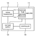
- FIG. 1 is a block diagram illustrating a configuration of an electronic device 1 according to an exemplary embodiment.
- the electronic device 1 may include an amplifier 110 , a voltage supply 120 , a controller 100 , and a signal transceiver 130 .
- the amplifier 110 may include a vacuum tube 112 which amplifies a sound signal, and the vacuum 112 may include a heater 114 .
- the voltage supply 120 may supply one of a first voltage and a second voltage, which is higher than the first voltage, to the heater 114 .
- the controller 100 may control the voltage supply 120 to supply the second voltage to the heater 114 when supply of a drive voltage to the amplifier 110 is started, and to supply the first voltage to the heater 114 when the vacuum tube 112 reaches a predetermined temperature.
- the signal transceiver 130 may transmit a signal received from an external device or source to the amplifier 100 , and may be realized in various forms according to the characteristic and standard of the received signal, the types of the external device or source, the type of the electronic device 1 , or the like.
- the signal transceiver 130 may receive a signal or data according to a standard such as a high definition multimedia interface (HDMI), a universal serial bus (USB), a component or the like, and may include at least one connector corresponding to the standard.
- HDMI high definition multimedia interface
- USB universal serial bus
- the signal transceiver 130 may also transmit information, data or a signal of the electronic device 1 to the external device or source. That is, the signal transceiver 130 may be provided with an interface capable of two-way communication for signal reception and transmission with respect to the external device or source.
- the amplifier 110 amplifies an input sound signal.
- the amplification is performed to enlarge the waveform, voltage or current of the signal.
- a low frequency amplifier is typically used in the audio field.
- the amplifier 110 may include the vacuum tube 112 .
- the vacuum tube 112 may amplify a sound signal, and may output the amplified sound signal.
- the heater 114 is turned on in vacuum, a plate which surrounds the heater 114 is heated to emit electrons. Then, the emitted electrons move to a cathode. In the course of movement of the electrons, an appropriate voltage is applied to a grid electrode, and thus, properties of the electrons are changed, to thereby achieve the sound signal amplification.
- the heater 114 included in the vacuum tube 112 may have a heating function.
- the heater 114 may preheat the vacuum tube 112 , and may emit heat to maintain an appropriate temperature during the sound signal amplification.
- the amplifier 110 according to the present exemplary embodiment is different from a speaker which simply increases a sound output in that the amplifier 110 outputs sound with high quality without distortion of a sound signal received through the signal transceiver 130 .
- the voltage supply 120 may supply the first voltage or the second voltage, which is higher than the first voltage, to the heater 14 .
- the first voltage may be a DC voltage of 6.3V which is supplied to generate heat for normal sound amplification of the vacuum tube 112
- the second voltage may be a DC voltage of 12.6V which is supplied to rapidly preheat the heater 114 of the vacuum tube 112 .
- the voltage supply 120 may include a converter (not shown) which changes the size of a DC voltage to supply an output voltage.
- the converter may include a resistor mounted on a printed circuit board (not shown).
- the voltage supply 120 may selectively supply the first voltage or the second voltage by switching.
- the controller 100 may control the voltage supply 120 to supply the second voltage to the heater 114 when the supply of the drive voltage to the amplifier 110 is started, and to supply the first voltage to the heater 114 when the vacuum tube 112 reaches the predetermined temperature.
- the voltage supply 120 may supply voltage to the amplifier 110 , that is, to the heater 114 to preheat the vacuum tube 112 .
- the second voltage instead of the first voltage, is supplied to the heater 114 to rapidly preheat the vacuum tube 112 .
- the voltage supply 120 may supply the first voltage, instead of the second voltage, to the heater 114 .
- FIG. 2 is a circuit diagram illustrating a process of supplying the second voltage to preheat the vacuum tube 112 of the electronic device 1 , according to an exemplary embodiment.
- the vacuum tube 112 includes a plate, the heater 114 , a cathode and a grid electrode.
- the plate surrounds the heater 114 .
- the heater 114 is turned on by the second voltage higher than the first voltage which is a normal voltage.
- the plate which surrounds the heater 114 is heated to emit electrons. Then, the emitted electrons move to the cathode. In the course of the movement of the electrons, an appropriate voltage is applied to the grid electrode, and thus, properties of the electrons are changed due to electron amplification, to thereby achieve sound amplification.
- the voltage supply 120 supplies voltage to the amplifier 110 , and accordingly, to the heater 114 of the vacuum tube 112 .
- the first voltage is supplied to the heater 114 in the related art
- the second voltage higher than the first voltage is supplied to the heater 114 under the control of the controller 100 , according to the present exemplary embodiment.
- the voltage supply 120 may adjust the voltage using a converter to supply the first voltage or the second voltage.
- the vacuum tube 112 may be rapidly preheated. Then, if the vacuum tube 112 reaches the predetermined temperature, the voltage supply 120 may change the second voltage to the first voltage to supply the first voltage to the heater 114 .
- FIG. 3 is a block diagram illustrating a configuration of an electronic device according to another exemplary embodiment.
- an electronic device 1 according to the present exemplary embodiment may further include a switch 140 and a temperature sensor 116 as compared with the electronic device 1 shown in FIG. 1 .
- the second voltage is supplied to the heater 114 of the vacuum tube 112 in response to the drive voltage being supplied to the electronic device 1 . Then, if the vacuum tube 112 reaches the predetermined temperature, the first voltage is supplied to the heater.
- the supply of the drive voltage to the electronic device 1 may be cut off.
- the controller 100 may control the switch 140 to supply a standby voltage lower than the first voltage to the vacuum tube 112 from the voltage supply 120 .
- the temperature sensor 116 may detect the temperature of the vacuum tube 112 .
- the temperature sensor 116 may detect the temperature of the vacuum tube 112 and may transmit the result to the controller 100 . If the vacuum tube 112 reaches the predetermined temperature, the controller 100 may control the voltage supply 120 to change the second voltage to the first voltage to supply the first voltage to the heater 114 .
- the switch 140 may include a resistor that is provided to adjust voltage. If the supply of the drive voltage to the electronic device 1 is cut off, the switch 140 may adjust the voltage through the resistor to obtain the standby voltage. Thus, the switch 140 may supply the standby voltage to the heater 114 . Thereafter, if the drive voltage is again supplied to the electronic device 1 , the voltage supply 120 may supply the first voltage or the second voltage. With this configuration, it is possible to preheat the vacuum tube 112 using the standby voltage even when the drive voltage is not supplied to the electronic device 1 , and to rapidly preheat the vacuum tube 112 when the drive voltage is again supplied to the electronic device 1 .
- FIG. 4 is a schematic circuit diagram illustrating a process of supplying the standby voltage and the first and second voltages to preheat the vacuum tube 112 of the electronic device 1 , according to an exemplary embodiment.
- the standby voltage is supplied to the heater 114 of the vacuum tube 112 through the switch 140 under the control of the controller 100 , to thereby perform the preheating operation until the drive voltage is again supplied to the electronic device 1 .
- a power line for supplying the first voltage and the second voltage and a power line for supplying the standby voltage may be separately provided.
- the two power lines are switched by the switch 140 under the control of the controller 100 , to thereby supply the different voltages. That is, if the drive voltage is not supplied to the electronic device 1 , the standby voltage is supplied, and if the drive voltage is supplied to the electronic device 1 , the first voltage or the second voltage is supplied.
- the first voltage or the second voltage is selectively supplied under the control of the controller 100 .
- the second voltage may be first supplied to the vacuum tube 112 , and then, if the vacuum tube 112 reaches the predetermined temperature, the first voltage is supplied.
- FIG. 5 is a control flowchart illustrating operation of the electronic device 1 according to an exemplary embodiment.
- the drive voltage is supplied to the electronic device 1 (S 10 ).
- the drive voltage is supplied to the voltage supply 120 , and is then supplied to the vacuum tube 112 of the amplifier 110 .
- the second voltage is supplied from the voltage supply 120 to the heater 114 of the vacuum tube 112 (S 12 ). Since the second voltage, which higher than the first voltage, is supplied to the heater 114 , the heater 114 is rapidly heated to rapidly preheat the vacuum tube 112 . Then, when the vacuum tube 112 reaches the predetermined temperature, the voltage supply 120 changes the second voltage to the first voltage under the control of the controller 100 , and supplies the first voltage to the heater 114 (S 14 ).
- FIG. 6 is a control flowchart illustrating an operation of the electronic device 1 which supplies the standby voltage and the first and second voltages to preheat the vacuum tube 112 of the electronic device 1 , according to an exemplary embodiment.
- the drive voltage is supplied to the electronic device 1 (S 20 ).
- the drive voltage is supplied to the voltage supply 120 , and is then supplied to the vacuum tube 112 of the amplifier 110 .
- the second voltage is supplied from the voltage supply 120 to the heater 114 of the vacuum tube 112 (S 21 ). Since the second voltage, which is higher than the first voltage, is supplied to the heater 114 , the heater 114 is rapidly heated to rapidly preheat the vacuum tube 112 . Then, if the vacuum tube 112 reaches the predetermined temperature, the voltage supply 120 changes the second voltage to the first voltage under the control of the controller 100 , and supplies the first voltage to the heater 114 (S 22 ).
- the supply of the drive voltage to the electronic device 1 is cut off by a user (S 23 ).
- the controller 100 controls the switch 140 to perform switching for supply of the standby voltage.
- the standby voltage is supplied to the heater 114 of the vacuum 112 (S 24 ). Since the standby voltage is lower than the first voltage, a large amount of heat does not occur in heating the vacuum tube 112 . Further, the standby voltage may be changed according to the type of the electronic device 1 . In this case, it is possible to suppress overheating of the vacuum tube 112 using the temperature sensor 116 . Then, the drive voltage is again supplied to the electronic device 1 by the user (S 25 ).
- the controller 100 controls the switch 140 to perform switching for supply of the first voltage or the second voltage.
- the voltage supply 120 supplies the first voltage or the second voltage to the heater 114 (S 26 ).
- the temperature of the vacuum tube 112 is similarly detected by the temperature sensor 116 . If the detected temperature is lower than the predetermined temperature, the second voltage is supplied to the heater 114 , and if the detected temperature is equal to or higher than the predetermined temperature, the first voltage is supplied to the heater 114 .
- FIG. 7 is a control flowchart illustrating an operation of the electronic device 1 which preheats the vacuum tube 112 using the temperature sensor 116 , according to an exemplary embodiment.
- the drive voltage is supplied to the electronic device 1 (S 30 ).
- the drive voltage is supplied to the voltage supply 120 , and is then supplied to the vacuum tube 112 of the amplifier 110 .
- the controller 100 determines whether the temperature of the vacuum tube 112 detected by the temperature sensor 116 is equal to or higher than the predetermined temperature (S 31 ). If the detected temperature is equal to or higher than the predetermined temperature, the controller 100 controls the voltage supply 120 to supply the first voltage to the heater 114 of the vacuum tube 112 . On the other hand, if the detected temperature is lower than the predetermined temperature, the controller 100 controls the voltage supply 120 to supply the second voltage to the heater 114 of the vacuum tube 112 (S 32 ).
- the controller 100 determines whether the vacuum tube 112 reaches the predetermined temperature, using the temperature sensor 116 (S 33 ). If the vacuum tube 112 has not reached the predetermined temperature, the controller 100 controls the voltage supply 120 to continue to supply the second voltage (S 32 ). If the vacuum tube 112 reaches the predetermined temperature, the controller 100 controls the voltage supply 120 to change the second voltage to the first voltage and to supply the first voltage to the heater 114 (S 34 ).
- FIG. 8 is a control flowchart illustrating an operation of the electronic device 1 which supplies the standby voltage and the first and second voltages to preheat the vacuum tube 112 using the temperature sensor 116 , according to an exemplary embodiment.
- the drive voltage is supplied to the electronic device 1 (S 40 ).
- the drive voltage is supplied to the voltage supply 120 , and is then supplied to the vacuum tube 112 of the amplifier 110 .
- the controller 100 determines whether the temperature of the vacuum tube 112 detected by the temperature sensor 116 is equal to or higher than the predetermined temperature (S 41 ). If the detected temperature is equal to or higher than the predetermined temperature, the controller 100 controls the voltage supply 120 to supply the first voltage to the heater 114 of the vacuum tube 112 . On the other hand, if the detected temperature is lower than the predetermined temperature, the controller 100 controls the voltage supply 120 to supply the second voltage to the heater 114 of the vacuum tube 112 (S 42 ).
- the controller 100 determines whether the vacuum tube 112 reaches the predetermined temperature, using the temperature sensor 116 (S 43 ). If the vacuum tube 112 has not reached the predetermined temperature, the controller 100 controls the voltage supply 120 to continue to supply the second voltage (S 42 ). If the vacuum tube 112 reaches the predetermined temperature, the controller 100 controls the voltage supply 120 to change the second voltage to the first voltage and to supply the first voltage to the heater 114 (S 44 ). Then, the controller 100 determines whether the supply of the drive voltage to the electronic device 1 is cut off by a user (S 45 ).
- the controller 100 controls the voltage supply 120 to continue to supply the first voltage (S 44 ). If the supply of the drive voltage is cut off, the controller 100 controls the switch 140 to perform switching for supply of the standby voltage.
- the standby voltage is supplied to the heater 114 of the vacuum tube 112 (S 46 ). Since the standby voltage is lower than the first voltage, a large amount of heat does not occur in heating the vacuum tube 112 . Further, the standby voltage may be changed according to the type of the electronic device 1 . Thus, it is possible to suppress overheating of the vacuum tube 112 using the temperature sensor 116 . Then, the drive voltage is again supplied to the electronic device 1 by the user (S 47 ).
- the controller 100 controls the switch 140 to perform switching for supply of the first voltage or the second voltage.
- the voltage supply 120 supplies the first voltage or the second voltage (S 48 ).
- the temperature of the vacuum tube 112 is similarly detected by the temperature sensor 116 . Then, if the detected temperature is lower than the predetermined temperature, the second voltage is supplied to the heater 114 , and if the detected temperature is equal to or higher than the predetermined temperature, the first voltage is supplied to the heater 114 .
Landscapes
- Engineering & Computer Science (AREA)
- Power Engineering (AREA)
- Multimedia (AREA)
- Amplifiers (AREA)
Abstract
Description
Claims (7)
Applications Claiming Priority (2)
| Application Number | Priority Date | Filing Date | Title |
|---|---|---|---|
| KR1020120152197A KR102088173B1 (en) | 2012-12-24 | 2012-12-24 | Electronic device and control method for the same |
| KR10-2012-0152197 | 2012-12-24 |
Publications (2)
| Publication Number | Publication Date |
|---|---|
| US20140176237A1 US20140176237A1 (en) | 2014-06-26 |
| US9413304B2 true US9413304B2 (en) | 2016-08-09 |
Family
ID=50071381
Family Applications (1)
| Application Number | Title | Priority Date | Filing Date |
|---|---|---|---|
| US14/139,907 Expired - Fee Related US9413304B2 (en) | 2012-12-24 | 2013-12-24 | Electronic device and control method thereof |
Country Status (3)
| Country | Link |
|---|---|
| US (1) | US9413304B2 (en) |
| EP (1) | EP2747280B1 (en) |
| KR (1) | KR102088173B1 (en) |
Citations (16)
| Publication number | Priority date | Publication date | Assignee | Title |
|---|---|---|---|---|
| US2040014A (en) * | 1934-07-03 | 1936-05-05 | Sperry Gyroscope Co Inc | Antihunting positional control |
| US2084180A (en) | 1932-01-15 | 1937-06-15 | Rca Corp | Radio signaling system |
| US2207450A (en) * | 1938-08-03 | 1940-07-09 | Kenneth N Bergan | Musical tuning instrument |
| CA391667A (en) | 1940-10-01 | The Lorain Telephone Company | Radio communication system | |
| US2357237A (en) * | 1938-07-20 | 1944-08-29 | Philco Radio & Television Corp | Remote control system for radio receivers and the like |
| US2423540A (en) * | 1941-12-01 | 1947-07-08 | Brown Instr Co | Self-balancing potentiometer mechanism |
| US2440289A (en) * | 1943-02-18 | 1948-04-27 | Sperry Corp | Automatic volume control for pulse systems |
| US2519615A (en) * | 1945-03-27 | 1950-08-22 | Honeywell Regulator Co | Analyzing apparatus |
| US2523017A (en) * | 1946-04-11 | 1950-09-19 | Honeywell Regulator Co | Detonation detector system |
| US2527893A (en) * | 1948-07-29 | 1950-10-31 | Honeywell Regulator Co | Motor control apparatus |
| US2540089A (en) * | 1944-05-17 | 1951-02-06 | Eastern Ind Inc | Vehicle detector |
| US2554717A (en) * | 1946-01-26 | 1951-05-29 | Honeywell Regulator Co | Measuring and controlling apparatus |
| US2601583A (en) * | 1947-05-26 | 1952-06-24 | Charles O Ballou | Radiation measuring instrument |
| US2872588A (en) * | 1953-11-16 | 1959-02-03 | Phillips Petroleum Co | Analyzer |
| US3305000A (en) * | 1965-02-08 | 1967-02-21 | Barber Colman Co | Temperature control system for chromatographs |
| US20040257158A1 (en) | 2003-04-03 | 2004-12-23 | Fumio Mieda | Vacuum tube amplifier |
Family Cites Families (2)
| Publication number | Priority date | Publication date | Assignee | Title |
|---|---|---|---|---|
| KR19990056513A (en) * | 1997-12-29 | 1999-07-15 | 전주범 | Heater driving control device of microwave generator tube used in microwave oven |
| JP4267435B2 (en) * | 2003-04-07 | 2009-05-27 | 株式会社日立国際電気 | Transmit amplifier |
-
2012
- 2012-12-24 KR KR1020120152197A patent/KR102088173B1/en not_active Expired - Fee Related
-
2013
- 2013-12-19 EP EP13198647.3A patent/EP2747280B1/en not_active Not-in-force
- 2013-12-24 US US14/139,907 patent/US9413304B2/en not_active Expired - Fee Related
Patent Citations (16)
| Publication number | Priority date | Publication date | Assignee | Title |
|---|---|---|---|---|
| CA391667A (en) | 1940-10-01 | The Lorain Telephone Company | Radio communication system | |
| US2084180A (en) | 1932-01-15 | 1937-06-15 | Rca Corp | Radio signaling system |
| US2040014A (en) * | 1934-07-03 | 1936-05-05 | Sperry Gyroscope Co Inc | Antihunting positional control |
| US2357237A (en) * | 1938-07-20 | 1944-08-29 | Philco Radio & Television Corp | Remote control system for radio receivers and the like |
| US2207450A (en) * | 1938-08-03 | 1940-07-09 | Kenneth N Bergan | Musical tuning instrument |
| US2423540A (en) * | 1941-12-01 | 1947-07-08 | Brown Instr Co | Self-balancing potentiometer mechanism |
| US2440289A (en) * | 1943-02-18 | 1948-04-27 | Sperry Corp | Automatic volume control for pulse systems |
| US2540089A (en) * | 1944-05-17 | 1951-02-06 | Eastern Ind Inc | Vehicle detector |
| US2519615A (en) * | 1945-03-27 | 1950-08-22 | Honeywell Regulator Co | Analyzing apparatus |
| US2554717A (en) * | 1946-01-26 | 1951-05-29 | Honeywell Regulator Co | Measuring and controlling apparatus |
| US2523017A (en) * | 1946-04-11 | 1950-09-19 | Honeywell Regulator Co | Detonation detector system |
| US2601583A (en) * | 1947-05-26 | 1952-06-24 | Charles O Ballou | Radiation measuring instrument |
| US2527893A (en) * | 1948-07-29 | 1950-10-31 | Honeywell Regulator Co | Motor control apparatus |
| US2872588A (en) * | 1953-11-16 | 1959-02-03 | Phillips Petroleum Co | Analyzer |
| US3305000A (en) * | 1965-02-08 | 1967-02-21 | Barber Colman Co | Temperature control system for chromatographs |
| US20040257158A1 (en) | 2003-04-03 | 2004-12-23 | Fumio Mieda | Vacuum tube amplifier |
Non-Patent Citations (1)
| Title |
|---|
| European Search Report dated May 2, 2014 issued by the European Patent Office in counterpart European Patent Application No. 13198647.3. |
Also Published As
| Publication number | Publication date |
|---|---|
| EP2747280A1 (en) | 2014-06-25 |
| US20140176237A1 (en) | 2014-06-26 |
| EP2747280B1 (en) | 2016-07-27 |
| KR20140082342A (en) | 2014-07-02 |
| KR102088173B1 (en) | 2020-03-12 |
Similar Documents
| Publication | Publication Date | Title |
|---|---|---|
| EP2502337B1 (en) | Power supplying system | |
| CN103313363B (en) | Power management apparatus and method | |
| US20110080046A1 (en) | Master and slave power outlet system | |
| US9467041B2 (en) | Digital current equalizing device, analog current equalizing device, current equalizing method and system | |
| US20160065139A1 (en) | Method and apparatus for supplying power to a radio frequency power amplifier | |
| TWI519082B (en) | Wireless communication apparatus and antenna switching method thereof | |
| US10547307B2 (en) | Bias circuit and power amplifier having the same | |
| JP2019193265A (en) | Stabilizing high-performance audio amplifiers | |
| CN106060711A (en) | Audio playing device, terminal device and method | |
| US9413304B2 (en) | Electronic device and control method thereof | |
| US20130259267A1 (en) | Audio amplifier apparatus | |
| US8717097B2 (en) | Amplifier with improved noise reduction | |
| CN106101933B (en) | Method and device for volume adjustment of power amplifier system | |
| CN102905211B (en) | Sound output device and audio apparatus for sound output thereof | |
| KR20210125373A (en) | Input voltage adjustment for amplyfying signal to be tranmitted and electonic device thereof | |
| US10404213B2 (en) | Method for controlling supply voltage of power amplifier, and electronic device | |
| KR102421372B1 (en) | Method and apparatus for improvement of current consmption according to heating in electronic device | |
| KR101868415B1 (en) | Sound output device using vacuum tube, audio apparatus and method for sound output thereof | |
| CN109218914B (en) | Audio playback device and audio transmission circuit | |
| CN1980488A (en) | Methods of Controlling Sound Output | |
| JP3122764U (en) | Audio output device and television broadcast receiver | |
| JP2010206470A (en) | Amplifier | |
| KR101771560B1 (en) | Apparatus for adjusting power of wireless speaker | |
| JP2011139232A (en) | Electric apparatus | |
| US10715086B2 (en) | Amplifier circuit |
Legal Events
| Date | Code | Title | Description |
|---|---|---|---|
| AS | Assignment |
Owner name: SAMSUNG ELECTRONICS CO., LTD., KOREA, REPUBLIC OF Free format text: ASSIGNMENT OF ASSIGNORS INTEREST;ASSIGNORS:LEE, JAE-CHEOL;KIM, BYUNG-SOO;YOUN, JOO-MOON;AND OTHERS;REEL/FRAME:031844/0455 Effective date: 20131217 |
|
| FEPP | Fee payment procedure |
Free format text: PAYOR NUMBER ASSIGNED (ORIGINAL EVENT CODE: ASPN); ENTITY STATUS OF PATENT OWNER: LARGE ENTITY |
|
| ZAAA | Notice of allowance and fees due |
Free format text: ORIGINAL CODE: NOA |
|
| ZAAB | Notice of allowance mailed |
Free format text: ORIGINAL CODE: MN/=. |
|
| STCF | Information on status: patent grant |
Free format text: PATENTED CASE |
|
| MAFP | Maintenance fee payment |
Free format text: PAYMENT OF MAINTENANCE FEE, 4TH YEAR, LARGE ENTITY (ORIGINAL EVENT CODE: M1551); ENTITY STATUS OF PATENT OWNER: LARGE ENTITY Year of fee payment: 4 |
|
| FEPP | Fee payment procedure |
Free format text: MAINTENANCE FEE REMINDER MAILED (ORIGINAL EVENT CODE: REM.); ENTITY STATUS OF PATENT OWNER: LARGE ENTITY |
|
| LAPS | Lapse for failure to pay maintenance fees |
Free format text: PATENT EXPIRED FOR FAILURE TO PAY MAINTENANCE FEES (ORIGINAL EVENT CODE: EXP.); ENTITY STATUS OF PATENT OWNER: LARGE ENTITY |
|
| STCH | Information on status: patent discontinuation |
Free format text: PATENT EXPIRED DUE TO NONPAYMENT OF MAINTENANCE FEES UNDER 37 CFR 1.362 |
|
| FP | Lapsed due to failure to pay maintenance fee |
Effective date: 20240809 |