US9413094B2 - Terminal for an electrical connector - Google Patents
Terminal for an electrical connector Download PDFInfo
- Publication number
- US9413094B2 US9413094B2 US14/601,676 US201514601676A US9413094B2 US 9413094 B2 US9413094 B2 US 9413094B2 US 201514601676 A US201514601676 A US 201514601676A US 9413094 B2 US9413094 B2 US 9413094B2
- Authority
- US
- United States
- Prior art keywords
- terminal
- folding
- contacting
- extension section
- section
- Prior art date
- Legal status (The legal status is an assumption and is not a legal conclusion. Google has not performed a legal analysis and makes no representation as to the accuracy of the status listed.)
- Active, expires
Links
- 238000004519 manufacturing process Methods 0.000 description 6
- 239000002184 metal Substances 0.000 description 3
- 229910052751 metal Inorganic materials 0.000 description 3
- 230000008054 signal transmission Effects 0.000 description 3
- 239000000463 material Substances 0.000 description 2
- 238000000034 method Methods 0.000 description 2
- RYGMFSIKBFXOCR-UHFFFAOYSA-N Copper Chemical compound [Cu] RYGMFSIKBFXOCR-UHFFFAOYSA-N 0.000 description 1
- 238000005452 bending Methods 0.000 description 1
- 229910052802 copper Inorganic materials 0.000 description 1
- 239000010949 copper Substances 0.000 description 1
Images


Classifications
-
- H—ELECTRICITY
- H01—ELECTRIC ELEMENTS
- H01R—ELECTRICALLY-CONDUCTIVE CONNECTIONS; STRUCTURAL ASSOCIATIONS OF A PLURALITY OF MUTUALLY-INSULATED ELECTRICAL CONNECTING ELEMENTS; COUPLING DEVICES; CURRENT COLLECTORS
- H01R13/00—Details of coupling devices of the kinds covered by groups H01R12/70 or H01R24/00 - H01R33/00
- H01R13/02—Contact members
- H01R13/10—Sockets for co-operation with pins or blades
- H01R13/11—Resilient sockets
- H01R13/113—Resilient sockets co-operating with pins or blades having a rectangular transverse section
-
- H—ELECTRICITY
- H01—ELECTRIC ELEMENTS
- H01R—ELECTRICALLY-CONDUCTIVE CONNECTIONS; STRUCTURAL ASSOCIATIONS OF A PLURALITY OF MUTUALLY-INSULATED ELECTRICAL CONNECTING ELEMENTS; COUPLING DEVICES; CURRENT COLLECTORS
- H01R4/00—Electrically-conductive connections between two or more conductive members in direct contact, i.e. touching one another; Means for effecting or maintaining such contact; Electrically-conductive connections having two or more spaced connecting locations for conductors and using contact members penetrating insulation
- H01R4/10—Electrically-conductive connections between two or more conductive members in direct contact, i.e. touching one another; Means for effecting or maintaining such contact; Electrically-conductive connections having two or more spaced connecting locations for conductors and using contact members penetrating insulation effected solely by twisting, wrapping, bending, crimping, or other permanent deformation
- H01R4/18—Electrically-conductive connections between two or more conductive members in direct contact, i.e. touching one another; Means for effecting or maintaining such contact; Electrically-conductive connections having two or more spaced connecting locations for conductors and using contact members penetrating insulation effected solely by twisting, wrapping, bending, crimping, or other permanent deformation by crimping
- H01R4/183—Electrically-conductive connections between two or more conductive members in direct contact, i.e. touching one another; Means for effecting or maintaining such contact; Electrically-conductive connections having two or more spaced connecting locations for conductors and using contact members penetrating insulation effected solely by twisting, wrapping, bending, crimping, or other permanent deformation by crimping for cylindrical elongated bodies, e.g. cables having circular cross-section
- H01R4/184—Electrically-conductive connections between two or more conductive members in direct contact, i.e. touching one another; Means for effecting or maintaining such contact; Electrically-conductive connections having two or more spaced connecting locations for conductors and using contact members penetrating insulation effected solely by twisting, wrapping, bending, crimping, or other permanent deformation by crimping for cylindrical elongated bodies, e.g. cables having circular cross-section comprising a U-shaped wire-receiving portion
- H01R4/185—Electrically-conductive connections between two or more conductive members in direct contact, i.e. touching one another; Means for effecting or maintaining such contact; Electrically-conductive connections having two or more spaced connecting locations for conductors and using contact members penetrating insulation effected solely by twisting, wrapping, bending, crimping, or other permanent deformation by crimping for cylindrical elongated bodies, e.g. cables having circular cross-section comprising a U-shaped wire-receiving portion combined with a U-shaped insulation-receiving portion
Definitions
- the present invention relates to a terminal, and more particularly to a terminal mounted in an electrical connector for signal transmission.
- the terminal has a resilient contacting arm for excellent electrically contacting and mechanically clamping functions without material fatigue after repeated plugging and pulling actions of the electrical connector. Furthermore, the terminal is manufactured easily such that the manufacturing cost is lowered.
- Electrical connectors are common components of electrical devices and are used to electrically connect different electrical devices such that signal transmission or power supply between the electrical devices is implemented through the electrical connectors.
- Taiwan utility model patent No. M415441 discloses an improved terminal mounted in an electrical connector on one end of a signal cable.
- the electrical connector may be engaged with a corresponding connector fabricated on a motherboard of an electrical device.
- the terminal has a base, a tail, two conducting portions, two contacting portions and two clamping portions.
- the tail protrudes from a rear end of the base.
- the conducting portions protrude from a front end of the base.
- the contacting portions protrude inward respectively from the conducting portions and extend forward.
- Each clamping portion extends from one of two sides of a corresponding conducting portion to the other side.
- the terminal is able to provide conducting and resiliently clamping effects.
- the contacting portions of the aforementioned terminal are thin and elongated such that contacting and positioning functions thereof are not ideal.
- the electrical connector on which the terminal is mounted suffers repeated plugging and pulling operations, the contacting portions of the terminal are fatigued and become too loose to maintain their original positions.
- the terminal cannot provide sufficient contacting force and results in contacting failure.
- the clamping portions of the terminal are hollow and U-shaped to decrease the clamping ability.
- the clamping portions are also too structurally complicated to manufacture. Therefore, the terminal has high manufacturing cost and low production yield rate.
- the present invention provides a terminal for an electrical connector to mitigate or obviate the aforementioned problems.
- the main objective of the invention is to provide a terminal mounted in an electrical connector for signal transmission.
- the terminal has a resilient contacting arm for excellent electrically contacting and mechanically clamping functions without material fatigue after repeated plugging and pulling actions of the electrical connector. Furthermore, the terminal is manufactured easily such that the manufacturing cost is lowered.
- a terminal in accordance with the present invention has a base, a wire covering portion, two connecting portions and two resilient arms.
- the resilient arms are formed on and protrude forward respectively from front ends of the connecting portions and each resilient arm has an extension section, a U-turn portion and a folding contacting section.
- the extension section is formed on and protrudes forward from the front end of one of the connecting portions.
- the U-turn portion is formed on the extension section.
- the folding contacting section is formed on and extends from the U-turn portion, is parallel to the other folding contacting section, and abuts an inside surface of the extension section.
- the terminal is structurally strong and durable.
- FIG. 1 is a perspective view of a first embodiment of a terminal for an electrical connector in accordance with the present invention
- FIG. 2 is another perspective view of the terminal in FIG. 1 ;
- FIG. 3 is a top view of the terminal in FIG. 1 ;
- FIG. 4 is a bottom view of the terminal in FIG. 1 ;
- FIG. 5 is a cross sectional side view of the terminal in FIG. 1 ;
- FIG. 6 is an operational and cross sectional side view of the terminal in FIG. 1 mounted in an insulative housing of an electrical connector;
- FIG. 7 is a perspective view of a second embodiment of a terminal for an electrical connector in accordance with the present invention.
- FIG. 8 is another perspective view of the terminal in FIG. 7 ;
- FIG. 9 is a top view of the terminal in FIG. 7 ;
- FIG. 10 is a bottom view of the terminal in FIG. 7 ;
- FIG. 11 is a cross sectional side view of the terminal in FIG. 7 ;
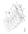
- FIG. 12 is an operational and cross sectional side view of the terminal in FIG. 7 mounted in an insulative housing of an electrical connector.
- a first embodiment of a terminal 1 in accordance with the present invention is mounted on an insulative housing 90 of an electrical connector and comprises a base 11 , a wire covering portion 16 , two connecting portions 12 , two resilient arms 13 and an abutting portion 14 .
- the wire covering portion 16 is formed on and protrudes backward from the base 11 and has multiple pairs of clamping tabs 161 .
- the pairs of the clamping tabs are formed on and protrude downward from the wire covering portion 16 and may be curved to tightly clamp copper wires of a cable connected to the electrical connector.
- the connecting portions 12 are formed on and protrude downward respectively from two opposite sides of the base 11 .
- the resilient arms 13 are formed by stamping processes, are formed on and protrude forward respectively from front ends of the connecting portions 12 , and each resilient arm 13 has an extension section 131 , a U-turn portion 133 and a folding contacting section 132 .
- the extension section 131 is formed on and protrudes forward from the front end of one of the connecting portions 12 .
- the U-turn portion 133 may be curved, and is formed on the extension section 131 .
- the U-turn portion 133 is formed on a front end of the extension section 131 .
- the folding contacting section 132 is formed on and extends from the U-turn portion 133 , is parallel to an inside surface of the extension section 131 , and abuts the inside surface of the extension section 131 . In the first embodiment, the folding contacting section 132 protrudes backward from the U-turn portion 133 .
- An inserting space 130 is defined between the folding contacting sections 132 of the resilient arms 13 .
- the folding contacting section 132 may further have a guiding slope surface 134 and a contacting bump 136 .
- the guiding slope surface 134 is formed in a bottom edge of the folding contacting section 132 to guide a corresponding terminal of an external electrical connector to smoothly enter the inserting space 130 .
- the contacting bump 136 is formed on and protrudes from an inside surface of the folding contacting section 132 to improve contacting effect.
- a length of the folding contacting section 132 is substantially equal to a length of the extension section 131 .
- the abutting portion 14 is formed on and protrudes forward from the base 11 and is located above the resilient arms 13 .
- a front end of the abutting portion 14 may be substantially flush with front ends of the resilient arms 13 .
- the abutting portion 14 may have an embedding protrusion 15 formed on and protruding from the abutting portion 14 .
- the embedding protrusion 15 is embedded into the insulative housing 90 to firmly mount the terminal 1 on the insulative housing 90 .
- a second embodiment of the terminal la in accordance with the present invention comprises a base 11 , a wire covering portion 16 , two connecting portions 12 a, two resilient arms 13 a and an abutting portion 14 .
- Each resilient arm 13 a has an extension section 131 , a U-turn portion 133 a, a folding contacting section 132 and a guiding slope surface 134 a.
- the U-turn portion 133 a of each resilient arm 13 a is formed on a bottom edge of the extension section 131 .
- the folding contacting section 132 of each resilient arm 13 a protrudes upward from the U-turn portion 133 a.
- a length of the connecting portion 12 a is longer than a length of the resilient arm 13 a.
- the terminal 1 , 1 a of the present invention has the following advantages.
- the terminal 1 , 1 a is manufactured from a one-piece metal sheet by stamping processes.
- Each resilient arm 13 , 13 a is made by folding an elongated metal sheet to form the abutting extension section 131 and the folding contacting section 132 such that the resilient arm 13 , 13 a has a thickness twice the thickness of the metal sheet. Therefore, structural strength of the resilient arm 13 , 13 a of the present invention is twice the structural strength of a conventional one and is able to provide excellent contacting, clamping and electrical conductive functions.
- the terminal 1 , 1 a of the present invention is durable. When the terminal 1 , 1 a is engaged with a corresponding terminal of another electrical connector, the inserting space 130 of the resilient arms 13 , 13 a accommodates and tightly clamps a contacting portion of the corresponding terminal to achieve excellent contacting and positioning purposes.
- the resilient arms are formed by bending reversely without any complicated structures of holes or U-shaped configurations, which improves the structural strength, facilitates the manufacture processing and lowers the cost of the resilient arms
Landscapes
- Connector Housings Or Holding Contact Members (AREA)
- Coupling Device And Connection With Printed Circuit (AREA)
- Connections Arranged To Contact A Plurality Of Conductors (AREA)
Abstract
Description
Claims (10)
Applications Claiming Priority (3)
| Application Number | Priority Date | Filing Date | Title |
|---|---|---|---|
| CN201410046436 | 2014-02-10 | ||
| CN201410046436.4 | 2014-02-10 | ||
| CN201410046436.4A CN103811906B (en) | 2014-02-10 | 2014-02-10 | The terminal of electric connector |
Publications (2)
| Publication Number | Publication Date |
|---|---|
| US20150229069A1 US20150229069A1 (en) | 2015-08-13 |
| US9413094B2 true US9413094B2 (en) | 2016-08-09 |
Family
ID=50708319
Family Applications (1)
| Application Number | Title | Priority Date | Filing Date |
|---|---|---|---|
| US14/601,676 Active 2035-02-14 US9413094B2 (en) | 2014-02-10 | 2015-01-21 | Terminal for an electrical connector |
Country Status (3)
| Country | Link |
|---|---|
| US (1) | US9413094B2 (en) |
| CN (1) | CN103811906B (en) |
| TW (1) | TWM497365U (en) |
Cited By (2)
| Publication number | Priority date | Publication date | Assignee | Title |
|---|---|---|---|---|
| US20180090900A1 (en) * | 2015-03-19 | 2018-03-29 | Autonetworks Technologies, Ltd. | Method for manufacturing female terminal and female terminal |
| US20180277976A1 (en) * | 2017-03-24 | 2018-09-27 | Ford Global Technologies, Llc | Genderless electric terminals for vehicles |
Families Citing this family (3)
| Publication number | Priority date | Publication date | Assignee | Title |
|---|---|---|---|---|
| CN106291000A (en) * | 2016-08-25 | 2017-01-04 | 太原鹏跃电子科技有限公司 | Passenger train feeder cable Insulation monitoring plug special connecting line |
| CN107394435A (en) * | 2017-06-19 | 2017-11-24 | 镇江天旭电气有限公司 | A kind of terminal unit |
| CN109216957B (en) * | 2018-09-05 | 2024-09-13 | 深圳市信维通信股份有限公司 | Assembled shell fragment connector |
Citations (22)
| Publication number | Priority date | Publication date | Assignee | Title |
|---|---|---|---|---|
| US2075632A (en) * | 1935-11-26 | 1937-03-30 | Irving Haas | Plug electric switch |
| US3120990A (en) * | 1958-10-15 | 1964-02-11 | Amp Inc | Electrical connector and connection |
| US3312931A (en) * | 1962-09-10 | 1967-04-04 | Amp Inc | Electrical connector and housing |
| US3609640A (en) * | 1969-11-17 | 1971-09-28 | Amp Inc | Precision receptacle alignment system |
| US3753193A (en) * | 1971-04-27 | 1973-08-14 | Amp Inc | Socket terminal |
| US3777301A (en) * | 1972-11-29 | 1973-12-04 | Molex Inc | Terminals and connectors for interconnecting conductors and male contacts |
| US3824557A (en) * | 1971-08-24 | 1974-07-16 | Interdyne Co | Electrical contact |
| US3846735A (en) * | 1971-03-26 | 1974-11-05 | Amp Inc | Electrical contact terminal which can be mated with an identical terminal or with a dissimilar terminal |
| US3853388A (en) * | 1972-10-17 | 1974-12-10 | Prod Inc Van | Cluster assembly and connector clip therefor |
| US3995930A (en) * | 1975-06-02 | 1976-12-07 | Amp Incorporated | High voltage tube connector |
| US4109992A (en) * | 1977-08-05 | 1978-08-29 | Amp Incorporated | Connector for compressor header |
| US4820179A (en) * | 1982-08-31 | 1989-04-11 | Nippon Acchakutanshi Seizo Kabushiki Kaisha | Multi-contact electrical connector |
| US5645458A (en) * | 1994-08-19 | 1997-07-08 | The Whitaker Corporation | Electrical receptacle terminal |
| US5730629A (en) * | 1995-09-14 | 1998-03-24 | Yazaki Corporation | Terminal parts and method of manufacturing same |
| US6280250B1 (en) * | 1998-12-07 | 2001-08-28 | Hon Hai Precision Ind. Co., Ltd. | Electrical connector with terminal retaining means |
| US6478620B1 (en) * | 2000-02-22 | 2002-11-12 | Tyco Electronics Logistics Ag | Electrical connector |
| US6520811B2 (en) * | 2000-12-21 | 2003-02-18 | Sumitomo Wiring Systems, Ltd. | Terminal fitting |
| US20040224573A1 (en) * | 2003-02-18 | 2004-11-11 | Yazaki Corporation | Female terminal |
| US7252561B2 (en) * | 2005-02-02 | 2007-08-07 | Sumitomo Wiring Systems, Ltd. | Terminal fitting and a connector provided therewith |
| US7704103B1 (en) * | 2009-02-02 | 2010-04-27 | Tyco Electronics Corporation | Low profile terminals |
| TWM415441U (en) | 2011-05-19 | 2011-11-01 | mu-rong Huang | Improvement for connector terminal |
| US8241076B2 (en) * | 2009-10-09 | 2012-08-14 | Sumitomo Wiring Systems, Ltd. | Female terminal fitting |
Family Cites Families (6)
| Publication number | Priority date | Publication date | Assignee | Title |
|---|---|---|---|---|
| US3964815A (en) * | 1975-02-26 | 1976-06-22 | Molex Incorporated | Insulation piercing terminal |
| US6120333A (en) * | 1998-12-07 | 2000-09-19 | Hon Hai Precision Ind. Co., Ltd. | Electric connector with terminal retaining means |
| JP2002343493A (en) * | 2001-05-18 | 2002-11-29 | Yazaki Corp | Terminal integrated seal member |
| CN202601901U (en) * | 2012-05-28 | 2012-12-12 | 艾恩特精密工业股份有限公司 | Conductive terminal |
| CN202855958U (en) * | 2012-08-14 | 2013-04-03 | 富士康(昆山)电脑接插件有限公司 | Cell connector and combination thereof |
| CN203800239U (en) * | 2014-02-10 | 2014-08-27 | 连展科技电子(昆山)有限公司 | Electrical connector terminal |
-
2014
- 2014-02-10 CN CN201410046436.4A patent/CN103811906B/en active Active
- 2014-07-25 TW TW103213232U patent/TWM497365U/en not_active IP Right Cessation
-
2015
- 2015-01-21 US US14/601,676 patent/US9413094B2/en active Active
Patent Citations (22)
| Publication number | Priority date | Publication date | Assignee | Title |
|---|---|---|---|---|
| US2075632A (en) * | 1935-11-26 | 1937-03-30 | Irving Haas | Plug electric switch |
| US3120990A (en) * | 1958-10-15 | 1964-02-11 | Amp Inc | Electrical connector and connection |
| US3312931A (en) * | 1962-09-10 | 1967-04-04 | Amp Inc | Electrical connector and housing |
| US3609640A (en) * | 1969-11-17 | 1971-09-28 | Amp Inc | Precision receptacle alignment system |
| US3846735A (en) * | 1971-03-26 | 1974-11-05 | Amp Inc | Electrical contact terminal which can be mated with an identical terminal or with a dissimilar terminal |
| US3753193A (en) * | 1971-04-27 | 1973-08-14 | Amp Inc | Socket terminal |
| US3824557A (en) * | 1971-08-24 | 1974-07-16 | Interdyne Co | Electrical contact |
| US3853388A (en) * | 1972-10-17 | 1974-12-10 | Prod Inc Van | Cluster assembly and connector clip therefor |
| US3777301A (en) * | 1972-11-29 | 1973-12-04 | Molex Inc | Terminals and connectors for interconnecting conductors and male contacts |
| US3995930A (en) * | 1975-06-02 | 1976-12-07 | Amp Incorporated | High voltage tube connector |
| US4109992A (en) * | 1977-08-05 | 1978-08-29 | Amp Incorporated | Connector for compressor header |
| US4820179A (en) * | 1982-08-31 | 1989-04-11 | Nippon Acchakutanshi Seizo Kabushiki Kaisha | Multi-contact electrical connector |
| US5645458A (en) * | 1994-08-19 | 1997-07-08 | The Whitaker Corporation | Electrical receptacle terminal |
| US5730629A (en) * | 1995-09-14 | 1998-03-24 | Yazaki Corporation | Terminal parts and method of manufacturing same |
| US6280250B1 (en) * | 1998-12-07 | 2001-08-28 | Hon Hai Precision Ind. Co., Ltd. | Electrical connector with terminal retaining means |
| US6478620B1 (en) * | 2000-02-22 | 2002-11-12 | Tyco Electronics Logistics Ag | Electrical connector |
| US6520811B2 (en) * | 2000-12-21 | 2003-02-18 | Sumitomo Wiring Systems, Ltd. | Terminal fitting |
| US20040224573A1 (en) * | 2003-02-18 | 2004-11-11 | Yazaki Corporation | Female terminal |
| US7252561B2 (en) * | 2005-02-02 | 2007-08-07 | Sumitomo Wiring Systems, Ltd. | Terminal fitting and a connector provided therewith |
| US7704103B1 (en) * | 2009-02-02 | 2010-04-27 | Tyco Electronics Corporation | Low profile terminals |
| US8241076B2 (en) * | 2009-10-09 | 2012-08-14 | Sumitomo Wiring Systems, Ltd. | Female terminal fitting |
| TWM415441U (en) | 2011-05-19 | 2011-11-01 | mu-rong Huang | Improvement for connector terminal |
Cited By (5)
| Publication number | Priority date | Publication date | Assignee | Title |
|---|---|---|---|---|
| US20180090900A1 (en) * | 2015-03-19 | 2018-03-29 | Autonetworks Technologies, Ltd. | Method for manufacturing female terminal and female terminal |
| US10290990B2 (en) * | 2015-03-19 | 2019-05-14 | Autonetworks Technologies, Ltd. | Method for manufacturing female terminal and female terminal |
| US20180277976A1 (en) * | 2017-03-24 | 2018-09-27 | Ford Global Technologies, Llc | Genderless electric terminals for vehicles |
| US10193261B2 (en) * | 2017-03-24 | 2019-01-29 | Ford Global Technologies, Llc | Genderless electric terminals for vehicles |
| US10530086B2 (en) | 2017-03-24 | 2020-01-07 | Ford Global Technologies, Llc | Genderless electric terminals for vehicles |
Also Published As
| Publication number | Publication date |
|---|---|
| US20150229069A1 (en) | 2015-08-13 |
| CN103811906A (en) | 2014-05-21 |
| TWM497365U (en) | 2015-03-11 |
| CN103811906B (en) | 2019-02-12 |
Similar Documents
| Publication | Publication Date | Title |
|---|---|---|
| US9502795B1 (en) | Clamping wire structure of terminal block | |
| US9413094B2 (en) | Terminal for an electrical connector | |
| CN203536589U (en) | Assembly of flexible flat cable and circuit board | |
| CN206364218U (en) | Electric connector | |
| CN104347973A (en) | Connector assembly | |
| CN105449384A (en) | Plug-in terminal structure | |
| US8137134B1 (en) | Coaxial cable connector with an insulating member with a bendable section with a pair of projections | |
| CN204558826U (en) | Cable connector | |
| KR101308613B1 (en) | Plug terminal for connector | |
| CN204376028U (en) | Idc connector male head | |
| CN204497439U (en) | A kind of binding post | |
| CN203942492U (en) | Photovoltaic junction box | |
| US9431736B2 (en) | Card edge connector and card edge connector assembly | |
| CN204885639U (en) | Fixing structure of flexible flat cable electric connector | |
| CN203645008U (en) | Wiring terminal | |
| CN103855535A (en) | Wire-to-Board Connector Assemblies with Pull Mechanism | |
| CN202167642U (en) | electrical connector | |
| CN204030037U (en) | SATA electric connector | |
| CN204558681U (en) | A kind of lug plate | |
| CN207009853U (en) | Easy-to-use waterproof cable structure | |
| CN205335436U (en) | Plug-in terminal structure | |
| TWM499672U (en) | Electrical connector | |
| CN204179268U (en) | Connector structure | |
| CN105305131A (en) | Electric connector and manufacturing method | |
| CN204497421U (en) | A kind of conducting terminal and the binding post with conducting terminal |
Legal Events
| Date | Code | Title | Description |
|---|---|---|---|
| AS | Assignment |
Owner name: ADVANCED-CONNECTEK INC., TAIWAN Free format text: ASSIGNMENT OF ASSIGNORS INTEREST;ASSIGNORS:QI, XIAO-JUAN;CHU, PING-CHUAN;DUAN, SHU-LIN;AND OTHERS;REEL/FRAME:034774/0492 Effective date: 20150121 |
|
| STCF | Information on status: patent grant |
Free format text: PATENTED CASE |
|
| MAFP | Maintenance fee payment |
Free format text: PAYMENT OF MAINTENANCE FEE, 4TH YEAR, LARGE ENTITY (ORIGINAL EVENT CODE: M1551); ENTITY STATUS OF PATENT OWNER: LARGE ENTITY Year of fee payment: 4 |
|
| MAFP | Maintenance fee payment |
Free format text: PAYMENT OF MAINTENANCE FEE, 8TH YEAR, LARGE ENTITY (ORIGINAL EVENT CODE: M1552); ENTITY STATUS OF PATENT OWNER: LARGE ENTITY Year of fee payment: 8 |