US9413041B2 - Method for adjusting nickel-metal hydride storage battery - Google Patents
Method for adjusting nickel-metal hydride storage battery Download PDFInfo
- Publication number
- US9413041B2 US9413041B2 US14/171,125 US201414171125A US9413041B2 US 9413041 B2 US9413041 B2 US 9413041B2 US 201414171125 A US201414171125 A US 201414171125A US 9413041 B2 US9413041 B2 US 9413041B2
- Authority
- US
- United States
- Prior art keywords
- battery
- discharge reserve
- valve opening
- charge amount
- capacity
- Prior art date
- Legal status (The legal status is an assumption and is not a legal conclusion. Google has not performed a legal analysis and makes no representation as to the accuracy of the status listed.)
- Active, expires
Links
- 229910052987 metal hydride Inorganic materials 0.000 title claims abstract description 56
- 238000000034 method Methods 0.000 title claims abstract description 28
- 239000007789 gas Substances 0.000 claims description 29
- MYMOFIZGZYHOMD-UHFFFAOYSA-N Dioxygen Chemical compound O=O MYMOFIZGZYHOMD-UHFFFAOYSA-N 0.000 claims description 14
- 229910001882 dioxygen Inorganic materials 0.000 claims description 14
- UFHFLCQGNIYNRP-UHFFFAOYSA-N Hydrogen Chemical compound [H][H] UFHFLCQGNIYNRP-UHFFFAOYSA-N 0.000 description 19
- 239000001257 hydrogen Substances 0.000 description 19
- 229910052739 hydrogen Inorganic materials 0.000 description 19
- 238000005259 measurement Methods 0.000 description 9
- 239000000956 alloy Substances 0.000 description 8
- 229910045601 alloy Inorganic materials 0.000 description 8
- 230000000875 corresponding effect Effects 0.000 description 8
- 238000012360 testing method Methods 0.000 description 8
- 238000010586 diagram Methods 0.000 description 6
- 239000003792 electrolyte Substances 0.000 description 6
- 230000033228 biological regulation Effects 0.000 description 5
- 238000006243 chemical reaction Methods 0.000 description 5
- 230000003247 decreasing effect Effects 0.000 description 5
- 230000007423 decrease Effects 0.000 description 3
- 230000006866 deterioration Effects 0.000 description 3
- 150000002431 hydrogen Chemical class 0.000 description 3
- 239000011347 resin Substances 0.000 description 3
- 229920005989 resin Polymers 0.000 description 3
- PXHVJJICTQNCMI-UHFFFAOYSA-N Nickel Chemical compound [Ni] PXHVJJICTQNCMI-UHFFFAOYSA-N 0.000 description 2
- 239000011149 active material Substances 0.000 description 2
- 230000002596 correlated effect Effects 0.000 description 2
- 238000000354 decomposition reaction Methods 0.000 description 2
- 230000012447 hatching Effects 0.000 description 2
- XLYOFNOQVPJJNP-ZSJDYOACSA-N heavy water Substances [2H]O[2H] XLYOFNOQVPJJNP-ZSJDYOACSA-N 0.000 description 2
- 230000007774 longterm Effects 0.000 description 2
- 239000000463 material Substances 0.000 description 2
- 238000012545 processing Methods 0.000 description 2
- XLYOFNOQVPJJNP-UHFFFAOYSA-N water Substances O XLYOFNOQVPJJNP-UHFFFAOYSA-N 0.000 description 2
- 239000003513 alkali Substances 0.000 description 1
- 230000007797 corrosion Effects 0.000 description 1
- 238000005260 corrosion Methods 0.000 description 1
- 230000007613 environmental effect Effects 0.000 description 1
- 238000002474 experimental method Methods 0.000 description 1
- 230000005484 gravity Effects 0.000 description 1
- 229910052759 nickel Inorganic materials 0.000 description 1
- BFDHFSHZJLFAMC-UHFFFAOYSA-L nickel(ii) hydroxide Chemical compound [OH-].[OH-].[Ni+2] BFDHFSHZJLFAMC-UHFFFAOYSA-L 0.000 description 1
- 239000004745 nonwoven fabric Substances 0.000 description 1
- 238000005192 partition Methods 0.000 description 1
- 239000012466 permeate Substances 0.000 description 1
- 230000000630 rising effect Effects 0.000 description 1
- 238000007789 sealing Methods 0.000 description 1
- 239000012209 synthetic fiber Substances 0.000 description 1
- 229920002994 synthetic fiber Polymers 0.000 description 1
Images


Classifications
-
- H—ELECTRICITY
- H01—ELECTRIC ELEMENTS
- H01M—PROCESSES OR MEANS, e.g. BATTERIES, FOR THE DIRECT CONVERSION OF CHEMICAL ENERGY INTO ELECTRICAL ENERGY
- H01M10/00—Secondary cells; Manufacture thereof
- H01M10/42—Methods or arrangements for servicing or maintenance of secondary cells or secondary half-cells
- H01M10/44—Methods for charging or discharging
-
- H—ELECTRICITY
- H01—ELECTRIC ELEMENTS
- H01M—PROCESSES OR MEANS, e.g. BATTERIES, FOR THE DIRECT CONVERSION OF CHEMICAL ENERGY INTO ELECTRICAL ENERGY
- H01M10/00—Secondary cells; Manufacture thereof
- H01M10/34—Gastight accumulators
- H01M10/345—Gastight metal hydride accumulators
-
- H01M2/1229—
-
- H—ELECTRICITY
- H01—ELECTRIC ELEMENTS
- H01M—PROCESSES OR MEANS, e.g. BATTERIES, FOR THE DIRECT CONVERSION OF CHEMICAL ENERGY INTO ELECTRICAL ENERGY
- H01M50/00—Constructional details or processes of manufacture of the non-active parts of electrochemical cells other than fuel cells, e.g. hybrid cells
- H01M50/30—Arrangements for facilitating escape of gases
- H01M50/317—Re-sealable arrangements
- H01M50/325—Re-sealable arrangements comprising deformable valve members, e.g. elastic or flexible valve members
-
- H—ELECTRICITY
- H02—GENERATION; CONVERSION OR DISTRIBUTION OF ELECTRIC POWER
- H02J—CIRCUIT ARRANGEMENTS OR SYSTEMS FOR SUPPLYING OR DISTRIBUTING ELECTRIC POWER; SYSTEMS FOR STORING ELECTRIC ENERGY
- H02J2310/00—The network for supplying or distributing electric power characterised by its spatial reach or by the load
- H02J2310/40—The network being an on-board power network, i.e. within a vehicle
- H02J2310/48—The network being an on-board power network, i.e. within a vehicle for electric vehicles [EV] or hybrid vehicles [HEV]
-
- H02J7/0057—
-
- H—ELECTRICITY
- H02—GENERATION; CONVERSION OR DISTRIBUTION OF ELECTRIC POWER
- H02J—CIRCUIT ARRANGEMENTS OR SYSTEMS FOR SUPPLYING OR DISTRIBUTING ELECTRIC POWER; SYSTEMS FOR STORING ELECTRIC ENERGY
- H02J7/00—Circuit arrangements for charging or depolarising batteries or for supplying loads from batteries
- H02J7/0069—Charging or discharging for charge maintenance, battery initiation or rejuvenation
-
- Y—GENERAL TAGGING OF NEW TECHNOLOGICAL DEVELOPMENTS; GENERAL TAGGING OF CROSS-SECTIONAL TECHNOLOGIES SPANNING OVER SEVERAL SECTIONS OF THE IPC; TECHNICAL SUBJECTS COVERED BY FORMER USPC CROSS-REFERENCE ART COLLECTIONS [XRACs] AND DIGESTS
- Y02—TECHNOLOGIES OR APPLICATIONS FOR MITIGATION OR ADAPTATION AGAINST CLIMATE CHANGE
- Y02E—REDUCTION OF GREENHOUSE GAS [GHG] EMISSIONS, RELATED TO ENERGY GENERATION, TRANSMISSION OR DISTRIBUTION
- Y02E60/00—Enabling technologies; Technologies with a potential or indirect contribution to GHG emissions mitigation
- Y02E60/10—Energy storage using batteries
-
- Y02E60/124—
Definitions
- the present invention relates to a method for adjusting a nickel-metal hydride storage battery.
- nickel-metal hydride storage batteries have been used as power sources for portable devices or power sources for electric vehicles or hybrid electric vehicles.
- the nickel-metal hydride storage batteries are normally designed so that the capacity of a negative electrode is larger than the capacity of a positive electrode.
- the discharge capacity of the battery is limited by the positive electrode capacity (hereinafter, also referred to as “positive electrode regulation”).
- This positive electrode regulation makes it possible to suppress an increase in internal pressure of the battery during overcharge and overdischarge. From contrast between the negative electrode and the positive electrode, an excess uncharged portion available for charge is referred to as charge reserve, while an excess charged portion available for discharge is referred to as discharge reserve.
- the nickel-metal hydride storage battery is subjected to the negative electrode regulation (meaning that the discharge capacity of the battery is limited by the negative electrode capacity). This results in a decrease in discharge capacity and a large deterioration in battery characteristics.
- the nickel-metal hydride storage battery is to be used as a power source of an electric vehicle, hybrid electric vehicle, etc., a long-term service life is demanded. Thus, the above deterioration in battery characteristics would be problematic.
- Patent Document 1 discloses a method including overcharging a nickel-metal hydride storage battery, releasing at least part of oxygen gas generated from a positive electrode to the outside of the battery, thereby increasing the discharge reserve capacity of a negative electrode.
- Patent Document 1 JP-A-2008-235036
- a nickel-metal hydride storage battery If a nickel-metal hydride storage battery is overcharged, electrons are emitted from a positive electrode and oxygen gas is generated by decomposition of electrolyte.
- oxygen gas is generated by decomposition of electrolyte.
- hydrogen generated by decomposition of water is absorbed in hydrogen absorbing alloy.
- the oxygen gas generated from the positive electrode is usually consumed by reaction with the hydrogen absorbed in the hydrogen absorbing alloy (thus generating water), so that the internal pressure of the battery is prevented from rising.
- Patent Document 1 on the other hand, the nickel-metal hydride storage battery is overcharged to allow at least part of oxygen gas generated from the positive electrode to release to the outside of the nickel-metal hydride storage battery. Accordingly, in the battery, the hydrogen absorbed in the hydrogen absorbing alloy of the negative electrode in association with overcharge is excessively increased with respect to oxygen gas. Consequently, at least a part of hydrogen absorbed in the hydrogen absorbing alloy of the negative electrode by overcharge is left absorbed in the hydrogen absorbing alloy (this hydrogen forms the discharge reserve) without reaction with the generated oxygen gas. Patent Document 1 proposes increasing the discharge reserve capacity of the negative electrode as above.
- the present invention has been made in view of the above circumstances and to provide a method for adjusting a nickel-metal hydride storage battery to increase a discharge reserve capacity of a negative electrode by a desired fixed capacity (a set target value).
- a method for adjusting a nickel-metal hydride storage battery including a positive electrode, a negative electrode, and a safety valve device, the method including a discharge reserve adjusting step of overcharging the battery and releasing at least a part of oxygen gas generated from the positive electrode to outside of the battery through the safety valve device brought into an open state, to increase a discharge reserve capacity of the negative electrode, wherein a correlation between a charge amount after valve opening charged in the battery after the safety valve device is opened within a period of overcharge of the battery and an increased amount of the discharge reserve capacity is ascertained in advance, the method further includes: a step of setting a target value of the increased amount of the discharge reserve capacity; and a step of calculating the charge amount after valve opening corresponding to the set target value of the increased amount of the discharge reserve capacity based on the previously ascertained correlation between the charge amount after valve opening and the increased amount of the discharge reserve capacity, and setting a calculated value as the target charge amount after valve opening in the discharge reserve adjusting
- the correlation between the “charge amount after valve opening” and the increased amount of the discharge reserve capacity is ascertained in advance, the “charge amount after valve opening (i.e., a charge amount after valve opening which is a charge amount in the nickel-metal hydride storage battery from the time when the safety valve device is opened after the start of overcharging the battery)” representing a charge amount of the nickel-metal hydride storage battery charged after the safety valve device is opened within a period of overcharging the nickel-metal hydride storage battery.
- the present inventors found there was a correlation between the increased amount of the discharge reserve capacity and the charge amount after valve opening.
- the increased amount of the discharge reserve capacity is proportional to the charge amount after valve opening (the overcharge amount after valve opening). Accordingly, in the above adjusting method, a proportional relationship (a proportional formula and a regression line) between the charge amount after valve opening and the increased amount of the discharge reserve capacity is determined in advance.
- the above adjusting method includes setting the target value of the increased amount of the discharge reserve capacity. Based on the correlation (a correlation chart and a correlation formula) between the charge amount after valve opening and the increased amount of the discharge reserve capacity previously ascertained, the charge amount after valve opening corresponding to the set target value (the increased amount of the discharge reserve capacity) is calculated, and this calculated value is set as the target charge amount after valve opening in the discharge reserve adjusting step.
- the nickel-metal hydride storage battery is overcharged, releasing at least part of the oxygen gas generated from the positive electrode to the outside of the nickel-metal hydride storage battery through the safety valve device brought into the open state, thereby increasing the discharge reserve capacity of the negative electrode.
- the charge amount of the nickel-metal hydride storage battery from the time when the safety valve device is opened (that is, when outside releasing of the oxygen gas is enabled) after the start of overcharge of the nickel-metal hydride storage battery reaches the set target charge amount after valve opening, the overcharge of the nickel-metal hydride storage battery is terminated. Accordingly, the discharge reserve capacity can be increased by the increased amount of the discharge reserve capacity corresponding to the charge amount after valve opening in the above correlation.
- the discharge reserve capacity of the negative electrode can be increased by a desired constant capacity (a set target value) can be increased.
- the safety valve device may include a safety valve device provided with a safety valve for keeping an air hole of a nickel-metal hydride storage battery in a sealed state while the internal pressure of the battery is less than a predetermined valve opening pressure, the safety valve being configured to automatically open the air hole from the sealed state when the internal pressure of the battery reaches the valve opening pressure, thereby releasing the gas out of the battery through the air hole.
- the discharge reserve adjusting step may be arranged to overcharge the nickel-metal hydride storage battery to cause the internal pressure in the battery to reach the valve opening pressure, thereby automatically opening the safety valve device (automatically opening the air hole from the sealed state by the safety valve).
- Another alternative is to forcibly open the safety valve device during overcharge before the internal pressure of the battery reaches the valve opening pressure (to forcibly open the air hole from the sealed state by the safety valve).
- the safety valve device is to be forcibly opened, it is preferable to open the safety valve device after the internal pressure of the battery exceeds outside air pressure (atmosphere pressure).
- the safety valve device includes a safety valve for keeping an air hole provided in the battery in a sealed state when an internal pressure of the battery is less than a predetermined valve opening pressure, the safety valve being configured to automatically open the air hole from the sealed state when the internal pressure of the battery reaches the valve opening pressure, to release gas in the battery to outside through the air hole, and the discharge reserve adjusting step includes terminating overcharge of the battery when a charge amount charged in the battery from the time when the safety valve automatically opens the air hole from the sealed state when the internal pressure of the battery reaches the valve opening pressure reaches the set target charge amount after valve opening.
- the discharge reserve adjusting step is arranged to terminate overcharging of the nickel-metal hydride storage battery when the charge amount of the nickel-metal hydride storage battery reaches the set target charge amount, the charge amount being counted from the time when the air hole is automatically opened from the sealed state by the safety valve when the internal pressure of the battery reaches a valve opening pressure after the start of overcharging the battery.
- the discharge reserve capacity of the negative electrode can be increased easily and simply by a desired constant capacity (a set target value).
- FIG. 1 is a top view of a nickel-metal hydride storage battery in an embodiment
- FIG. 2 is a side view of the nickel-metal hydride storage battery in the embodiment
- FIG. 3 is a cross sectional view taken along a line A-A in FIG. 1 , showing the inside of the nickel-metal hydride storage battery;
- FIG. 4 is an enlarged cross sectional view of a safety valve device of the nickel-metal hydride storage battery in the embodiment
- FIG. 5 is a view showing an open state of the safety valve device in the embodiment
- FIG. 6 is an explanatory diagram showing one example of a negative electrode discharge reserve
- FIG. 7 is an explanatory diagram showing another example of the negative electrode discharge reserve
- FIG. 8 is an explanatory diagram showing one example of a method for adjusting the negative electrode discharge reserve
- FIG. 9 is an explanatory diagram showing another example of the method for adjusting the negative electrode discharge reserve.
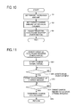
- FIG. 10 is a flowchart of a main routine of the method for adjusting the nickel-metal hydride storage battery in the embodiment
- FIG. 11 is a flowchart of a sub routine of the method for adjusting the nickel-metal hydride storage battery in the embodiment
- FIG. 12 is a graph showing results of a negative electrode reserve adjusting test, providing a correlation between a charge amount after valve opening and an increased amount of a discharge reserve capacity
- FIG. 13 is a schematic diagram of a discharge reserve adjusting device in the embodiment.
- This nickel-metal hydride storage battery 100 is a rectangular sealed nickel-metal hydride storage battery including a battery case 101 as shown in FIGS. 1 and 2 .
- the battery case 101 has a battery housing 102 and a lid 103 .
- This lid 103 is made of resin and has a substantially rectangular plate shape.
- This lid 103 is provided with a safety valve device 120 .
- the battery housing 102 is made of resin and has a substantially rectangular box shape.
- the safety valve device 120 includes a rubber safety valve 122 for sealing up an air hole 105 as shown in FIG. 3 .
- This safety valve 122 keeps the air hole 105 in a sealed state as shown in FIG. 4 while the internal pressure in the battery 100 (the battery case 101 ) is lower than a predetermined valve opening pressure.
- the safety valve 122 automatically opens the air hole 105 from the sealed state as shown in FIG. 5 to release gas G out of the battery 100 (the battery case 101 ) through the air hole 105 .
- a bottom 122 c of the safety valve 122 is pushed up by the pressure, thereby opening the air hole 105 from the sealed state. This allows the gas G in the battery 100 to be released to the outside through the air hole 105 .
- the inside of the battery case 101 (the battery housing 102 ) is partitioned into six chambers by partition walls 130 as shown in FIG. 3 .
- an electrode plate group 150 and an electrolyte (not shown) are contained in each of the chambers.
- six cells 110 are arranged.
- Each electrode plate group 150 includes positive electrodes 151 , negative electrodes 152 , and bag-shaped separators 153 .
- the positive electrodes 151 are inserted one in each of the bag-shaped separators 153 .
- the positive electrodes 151 inserted in the separators 153 and the negative electrodes 152 are alternately arranged in a stacking manner.
- the positive electrodes 151 and the negative electrodes 152 placed in each cell 110 are respectively current-collected and connected in series and also connected to a positive terminal 141 and a negative terminal 142 .
- Each positive electrode 151 may be formed for example of an electrode plate including an active material containing nickel hydroxide and an active material carrier such as foamed nickel.
- Each negative electrode 152 may be formed for example of an electrode plate containing hydrogen absorbing alloy as a negative electrode forming material.
- Each separator 153 may be formed for example of nonwoven fabric made of synthetic fibers subjected to a hydrophilic treatment.
- the electrolyte may include for example an alkali solution having a specific gravity of 1.2 to 1.4 and containing KOH.
- a plurality of unused nickel-metal hydride storage batteries 100 were prepared and subjected to measurement of an initial value of the capacity of discharge reserve DR of the negative electrodes 152 .
- each battery 100 was discharged until a battery voltage became 1 V per cell and then an electrolyte was added to each battery 100 so that the electrolyte be excessively present.
- an Hg/HgO reference electrode not shown was put. Each cell 110 was excessively discharged while measuring the discharge capacity.
- the initial value of the discharge reserve DR of the negative electrode 152 in each cell 110 was about 2.5 Ah on average (see FIG. 6 ).
- FIG. 6 is a schematic diagram showing a relationship between the capacity of the positive electrode 151 and the capacity of the negative electrode 152 in a battery 100 at an initial stage.
- the capacity of the positive electrode 151 and the capacity of the negative electrode 152 are respectively indicated by the length of a vertical band.
- the capacity of the discharge reserve DR is indicated by an arrow assuming that a downward direction from a zero reference line B 1 (a lower end of the positive electrode 151 , i.e., a point corresponding to a completely discharged point of the positive electrode 151 ) is a plus direction and an upward direction from the same is a minus direction.
- the capacity of the discharge reserve DR is a positive value, it is denoted as DR(+) (see FIG. 6 ).
- this capacity is a negative value, it is denoted as DR( ⁇ ) (see FIG. 7 ).
- a plurality of unused nickel-metal hydride storage batteries 100 were prepared and charged up to 60% SOC, and then left standing in a constant temperature chamber at 65° C. for six months.
- the temperature in the constant temperature chamber was set to a relatively high temperature, 65° C., in order to accelerate corrosion of the hydrogen absorbing alloy of the negative electrodes and also increase the hydrogen leakage amount.
- the nickel-metal hydride storage batteries 100 were being left standing in the constant temperature chamber, the nickel-metal hydride storage batteries 100 were recharged to 60% SOC every one month to prevent deep discharge of each battery (to prevent deterioration due to decreasing of the battery voltage below 1 V).
- Eleven batteries 100 prepared by decreasing the discharge reserve DR in the above manner were subjected to a negative electrode reserve adjusting test to increase (restore) the discharge reserve DR. Specifically, each battery 100 was subjected to overcharge (charging was continued even after 100% SOC was reached) and the oxygen gas (at least a part thereof) generated from the positive electrodes 151 was released to the outside of each battery 100 through the corresponding safety valve device 120 brought into an open state, thereby increasing (restoring) the discharge reserve DR.
- FIG. 9 shows an example that the capacity of the discharge reserve DR is increased to a “positive value”.
- the present invention is however not limited to such an example. According to the present invention, it is only necessary to perform a discharge reserve adjusting step to increase the capacity of the discharge reserve DR. This includes a case where the capacity of the discharge reserve DR after the discharge reserve adjusting step is performed becomes “0” or a “negative value”.
- the capacity of a charge reserve CR is indicated by arrows assuming that an upward direction from a zero reference line B 2 (an upper end of the positive electrode 151 , i.e., a point corresponding to a fully charged point of the positive electrode 151 ) is a plus direction and a downward direction from the same is a minus direction.
- the capacity of the charge reserve CR is a positive value, and thus this is expressed as CR(+).
- This test was performed using a discharge reserve adjusting device 1 shown in FIG. 13 .
- This device 1 includes a charge and discharge device 10 and a gas flow meter 20 .
- the charge and discharge device 10 is connected to the positive terminal 141 and the negative terminal 142 of the battery 100 through connecting cables 11 and 12 . Accordingly, the battery 100 can be charged and discharged by the charge and discharge device 10 .
- the safety valve device 120 of the battery 100 is connected to the gas flow meter 20 through a joining hose 21 .
- the gas flow meter 20 can detect the gas released out of the battery 100 through the opened safety valve device 120 . When the gas flow meter 20 detects an inflow of the gas thereto, it can be determined that the safety valve device 120 is opened.
- the internal pressure of the battery 100 gradually rises in association with overcharge, and finally reaches the valve opening pressure.
- the safety valve device 120 has a function of releasing the gas out of the battery 100 through the air hole 105 by automatically moving the safety valve 122 to open the air hole 105 from the sealed state when the internal pressure of the battery 100 rises and reaches the valve opening pressure. This function is referred to as an automatic gas release function in the present application.
- the automatic gas release function of the safety valve device 120 is utilized to release the oxygen gas (at least a part thereof) generated from the positive electrode 151 due to overcharge to the outside of the battery 100 through the air hole 105 .
- the safety valve device 120 is automatically opened (the air hole 105 sealed by the safety valve 122 is automatically opened).
- test environment temperatures were set to three different temperatures; 0° C., 25° C., and 30° C.
- three batteries 100 were charged (overcharged) at a constant current value of 20 A.
- seven batteries 100 were charged (overcharged) at a constant current value in a range of 2 A to 20 A.
- one battery 100 was charged (overcharged) at a constant current value of 20 A.
- each of the batteries 100 was subjected to measurement of an electric quantity (Ah) charged to each battery 100 from the time when an inflow of gas was detected by the gas flow meter 20 (i.e., when the safety valve device 120 was opened) to the termination of charge.
- This measurement value is referred to as “charge amount after valve opening (an electric quantity of the battery 100 charged after the safety valve device 120 is opened within an overcharge period of the battery 100 , namely, a charge amount in the battery 100 charged from the time when the safety valve device 120 is opened after the start of overcharging the battery 100 )”.
- the discharge reserve adjusting device 1 is configured so that when the gas flow meter 20 detects an inflow of gas, the information (signal) is transmitted to the charge and discharge device 10 , and subsequent charge amounts are ascertained.
- each of the nickel-metal hydride storage batteries 100 was subjected to measurement of the capacity of the discharge reserve DR of the negative electrodes 152 in the above manner.
- the results thereof are shown in FIG. 12 as the increased amount (Ah) of the discharge reserve capacity with respect to the charge amount after valve opening (Ah).
- FIG. 12 reveals that the increased amount of the discharge reserve capacity of the negative electrode is correlated (in a proportional relation) with the charge amount after valve opening of the batteries 100 charged after opening of the safety valve device 120 within the overcharge period of the battery 100 .
- results of the batteries 100 subjected to the adjusting treatment under the temperature environment of 0° C. are indicated by O (circular mark)
- results of the batteries 100 subjected to the adjusting treatment under the temperature environment of 25° C. are indicated by ⁇ (triangular mark)
- results of the batteries 100 subjected to the adjusting treatment under the temperature environment of 30° C. are indicated by ⁇ (square mark).
- FIG. 12 it is found that the “charge amount after valve opening” (Ah) and the increased amount (Ah) of the discharge reserve capacity are correlated in a proportional relationship irrespective of differences in temperature within the environmental temperature range of 0° to 30° C.
- the following manner can increase the discharge reserve capacity of the negative electrode by a desired constant capacity (a set target value).
- the target value of the increased amount of the discharge reserve capacity is set, for example, to 3.25 Ah.
- a charge amount after valve opening corresponding to the set target value of the increased amount of the discharge reserve capacity is calculated.
- the charge amount after valve opening is 5.0 Ah. This value is set as a target charge amount after valve opening in the discharge reserve adjusting step which will be mentioned later.
- the discharge reserve adjusting step subsequently, charging (overcharging) of the battery 100 is started and then it is checked whether or not the safety valve device 120 is opened.
- the safety valve device 120 When it is determined that the safety valve device 120 is opened, measurement of the charge amount of the battery 100 is started. Thereafter, when the charge amount of the battery 100 from the time when the safety valve device 120 is opened reaches the set target charge amount after valve opening (e.g., 5.0 Ah), charging (overcharge) of the battery 100 is terminated. Consequently, the discharge reserve capacity of the negative electrode can be increased by the set target value (e.g., 3.25 Ah).
- a target value of the increased amount (a target increased amount) of the discharge reserve capacity is set. For example, this target value is set to 3.25 Ah.
- the target charge amount after valve opening is set. To be concrete, based on the correlation between the charge amount after valve opening and the increased amount of the discharge reserve capacity which has been ascertained in advance (see FIG. 12 ), the charge amount after valve opening corresponding to the set target value of the increased amount of the discharge reserve capacity is calculated. In a case where the target value of the increased amount is set to 3.25 Ah, the charge amount after valve opening is calculated as 5.0 Ah (see FIG. 12 ). This calculated value is set to the target charge amount after valve opening in next step S 3 (discharge reserve adjusting step).
- step S 3 the discharge reserve adjusting (increasing) treatment is performed using the discharge reserve adjusting device 1 shown in FIG. 13 .
- the battery 100 having a decreased discharge reserve capacity is prepared and set in the discharge reserve adjusting device 1 (see FIG. 13 ).
- the positive terminal 141 and the negative terminal 142 of the battery 100 are connected to the charge and discharge device 10 through connecting cables 11 and 12 .
- the safety valve device 120 of the battery 100 is connected to the gas flow meter 20 .
- step 31 the charge and discharge device 10 starts charging (overcharging) the battery 100 .
- the flow advances to S 32 where it is determined whether the safety valve device 120 is opened. In the present embodiment, when the gas flow meter 20 detects an inflow of gas thereto, the safety valve device 120 is determined to be open. When it is determined in step S 32 that the safety valve device 120 is opened (S 32 : YES), the flow advances to step S 33 where the charge amount of the battery 100 charged from the time when the safety valve device 120 was opened starts to be measured.
- the automatic gas release function of the safety valve device 120 is utilized to release oxygen gas (at least a part thereof) generated from the positive electrode 151 by overcharge to the outside of the battery 100 through the air hole 105 .
- the safety valve device 120 is caused to automatically open; i.e., the air hole 105 sealed by the safety valve 122 is automatically opened.
- the gas released out of the battery 100 through the safety valve device 120 brought into the open state is allowed to flow in the gas flow meter 20 through the joining hose 21 .
- the discharge reserve adjusting device 1 in the present embodiment is configured such that when the gas flow meter 20 detects the inflow of gas, the information (signal) is transmitted to the charge and discharge device 10 and the subsequent charge amount can be ascertained. Accordingly, the processings in steps S 32 and S 33 are automatically performed in the discharge reserve adjusting device 1 .
- step S 34 it is determined whether or not the charged amount charged in the battery 100 after the safety valve device 120 is opened reaches the target charge amount after valve opening.
- the target charge amount after valve opening e.g., 5.0 Ah.
- the present invention is explained in the above embodiment, but the invention is not limited to the above and may be embodied in other specific forms without departing from the spirit or essential characteristics thereof.
- the above embodiment shows the nickel-metal hydride storage battery 100 including the resin battery case is subjected to adjustment of the capacity of the discharge reserve DR.
- the adjusting method of the invention is also applicable to a nickel-metal hydride storage battery including a battery case made of any other materials.
Abstract
Description
(Capacity of discharge reserve DR)=(Discharge capacity until an electric potential of the
By the above measurement, the initial value of the discharge reserve DR of the
(Positive Electrode) OH−→¼O2+½H2O+e − (1)
(Negative Electrode) M+H2O+e −→MH+OH− (2)
MH+¼O2→M+½H2O (3)
(Increased amount of discharge reserve capacity)=(Discharge reserve capacity after the discharge reserve adjusting treatment)−(Discharge reserve capacity before discharge reserve adjusting treatment)
The results thereof are shown in
| Reference Sings |
| 1 | |
10 | Charge and | |
| adjusting | discharge device | |||
| 20 | |
|||
| 100 | Nickel-metal | |||
| storage battery | ||||
| 101 | |
105 | |
|
| 120 | |
122 | |
|
| 141 | |
142 | |
|
| 151 | |
152 | Negative electrode | |
| CR | Charge reserve | DR | Discharge reserve | |
Claims (3)
Applications Claiming Priority (2)
| Application Number | Priority Date | Filing Date | Title |
|---|---|---|---|
| JP2013-059749 | 2013-03-22 | ||
| JP2013059749A JP5572731B1 (en) | 2013-03-22 | 2013-03-22 | Adjustment method of nickel metal hydride storage battery |
Publications (2)
| Publication Number | Publication Date |
|---|---|
| US20140285157A1 US20140285157A1 (en) | 2014-09-25 |
| US9413041B2 true US9413041B2 (en) | 2016-08-09 |
Family
ID=51427308
Family Applications (1)
| Application Number | Title | Priority Date | Filing Date |
|---|---|---|---|
| US14/171,125 Active 2034-10-16 US9413041B2 (en) | 2013-03-22 | 2014-02-03 | Method for adjusting nickel-metal hydride storage battery |
Country Status (3)
| Country | Link |
|---|---|
| US (1) | US9413041B2 (en) |
| JP (1) | JP5572731B1 (en) |
| CN (1) | CN104064830B (en) |
Cited By (1)
| Publication number | Priority date | Publication date | Assignee | Title |
|---|---|---|---|---|
| US10218037B2 (en) | 2016-07-05 | 2019-02-26 | Primearth Ev Energy Co., Ltd. | Method and device for regenerating nickel metal hydride battery |
Families Citing this family (5)
| Publication number | Priority date | Publication date | Assignee | Title |
|---|---|---|---|---|
| JP6632943B2 (en) * | 2016-07-21 | 2020-01-22 | プライムアースEvエナジー株式会社 | Nickel-metal hydride storage battery regeneration apparatus and nickel-metal hydride storage battery regeneration method |
| JP6933523B2 (en) * | 2017-07-27 | 2021-09-08 | アズビル株式会社 | Electric actuator |
| JP2019114439A (en) * | 2017-12-25 | 2019-07-11 | トヨタ自動車株式会社 | Manufacturing method of nickel hydrogen battery and nickel hydrogen battery |
| JP7036757B2 (en) * | 2019-02-25 | 2022-03-15 | プライムアースEvエナジー株式会社 | Nickel-metal hydride secondary battery regeneration method and nickel-metal hydride secondary battery regeneration device |
| JP7201632B2 (en) * | 2020-03-03 | 2023-01-10 | トヨタ自動車株式会社 | Battery system and its control method |
Citations (9)
| Publication number | Priority date | Publication date | Assignee | Title |
|---|---|---|---|---|
| US6281663B1 (en) * | 1999-11-11 | 2001-08-28 | Honda Giken Kogyo Kabushiki Kaisha | Battery charging method |
| US20020138971A1 (en) * | 2001-03-05 | 2002-10-03 | Matsushita Electric Industrial Co., Ltd. | Method for producing a nickel metal-hydride storage battery |
| US20030140483A1 (en) * | 1996-12-17 | 2003-07-31 | Toshiba Battery Co., Ltd. | Electrodes, alkaline secondary battery, and method for manufacturing alkaline secondary battery |
| US20040053114A1 (en) * | 2001-03-05 | 2004-03-18 | Kengo Furukawa | Method for manufacturing nickel hydrogen battery |
| US20040191619A1 (en) * | 2003-03-14 | 2004-09-30 | Matsushita Electric Industrial Co., Ltd. | Nickel metal hydride storage battery |
| US20080096096A1 (en) * | 2004-07-02 | 2008-04-24 | Katsunori Komori | Nickel-Metal Hydride Storage Battery |
| JP2008235036A (en) | 2007-03-21 | 2008-10-02 | Panasonic Ev Energy Co Ltd | Adjustment method for nickel hydrogen storage battery |
| US20100264929A1 (en) * | 2007-12-13 | 2010-10-21 | Panasonic Corporation | Lifetime estimating method and deterioration suppressing method for rechargeable lithium battery, lifetime estimating apparatus, deterioration suppressor, and battery pack and charger using the same |
| JP2011008963A (en) | 2009-06-23 | 2011-01-13 | Kyowa Technologies Co Ltd | Storage battery regenerating method, and storage battery regenerating device |
Family Cites Families (7)
| Publication number | Priority date | Publication date | Assignee | Title |
|---|---|---|---|---|
| JP4396127B2 (en) * | 2003-04-18 | 2010-01-13 | トヨタ自動車株式会社 | Recycling method of nickel metal hydride battery |
| JP4639641B2 (en) * | 2004-05-21 | 2011-02-23 | トヨタ自動車株式会社 | Sealed alkaline storage battery |
| CN100533843C (en) * | 2005-03-07 | 2009-08-26 | 上海万宏动力能源有限公司 | Method for controlling battery charging by gas sensor |
| JP2008189121A (en) * | 2007-02-05 | 2008-08-21 | Toyota Motor Corp | Hybrid vehicle |
| CN201638869U (en) * | 2010-01-08 | 2010-11-17 | 江苏奇能电池有限公司 | Battery module device capable of balancing air pressure of monomer |
| JP5684053B2 (en) * | 2011-06-13 | 2015-03-11 | プライムアースEvエナジー株式会社 | Sealed battery and safety valve |
| JP5720449B2 (en) * | 2011-07-11 | 2015-05-20 | トヨタ自動車株式会社 | Nickel metal hydride battery regeneration method and nickel metal hydride battery |
-
2013
- 2013-03-22 JP JP2013059749A patent/JP5572731B1/en active Active
-
2014
- 2014-02-03 US US14/171,125 patent/US9413041B2/en active Active
- 2014-02-28 CN CN201410071886.9A patent/CN104064830B/en active Active
Patent Citations (9)
| Publication number | Priority date | Publication date | Assignee | Title |
|---|---|---|---|---|
| US20030140483A1 (en) * | 1996-12-17 | 2003-07-31 | Toshiba Battery Co., Ltd. | Electrodes, alkaline secondary battery, and method for manufacturing alkaline secondary battery |
| US6281663B1 (en) * | 1999-11-11 | 2001-08-28 | Honda Giken Kogyo Kabushiki Kaisha | Battery charging method |
| US20020138971A1 (en) * | 2001-03-05 | 2002-10-03 | Matsushita Electric Industrial Co., Ltd. | Method for producing a nickel metal-hydride storage battery |
| US20040053114A1 (en) * | 2001-03-05 | 2004-03-18 | Kengo Furukawa | Method for manufacturing nickel hydrogen battery |
| US20040191619A1 (en) * | 2003-03-14 | 2004-09-30 | Matsushita Electric Industrial Co., Ltd. | Nickel metal hydride storage battery |
| US20080096096A1 (en) * | 2004-07-02 | 2008-04-24 | Katsunori Komori | Nickel-Metal Hydride Storage Battery |
| JP2008235036A (en) | 2007-03-21 | 2008-10-02 | Panasonic Ev Energy Co Ltd | Adjustment method for nickel hydrogen storage battery |
| US20100264929A1 (en) * | 2007-12-13 | 2010-10-21 | Panasonic Corporation | Lifetime estimating method and deterioration suppressing method for rechargeable lithium battery, lifetime estimating apparatus, deterioration suppressor, and battery pack and charger using the same |
| JP2011008963A (en) | 2009-06-23 | 2011-01-13 | Kyowa Technologies Co Ltd | Storage battery regenerating method, and storage battery regenerating device |
Cited By (1)
| Publication number | Priority date | Publication date | Assignee | Title |
|---|---|---|---|---|
| US10218037B2 (en) | 2016-07-05 | 2019-02-26 | Primearth Ev Energy Co., Ltd. | Method and device for regenerating nickel metal hydride battery |
Also Published As
| Publication number | Publication date |
|---|---|
| CN104064830B (en) | 2016-05-04 |
| JP2014186817A (en) | 2014-10-02 |
| CN104064830A (en) | 2014-09-24 |
| JP5572731B1 (en) | 2014-08-13 |
| US20140285157A1 (en) | 2014-09-25 |
Similar Documents
| Publication | Publication Date | Title |
|---|---|---|
| US9413041B2 (en) | Method for adjusting nickel-metal hydride storage battery | |
| US9692088B2 (en) | Method for restoring battery capacity, method for restoring battery pack capacity, device for restoring battery capacity, and device for restoring battery pack capacity | |
| US10644359B2 (en) | Storage battery controlling device, controlling method, non-transitory computer readable medium, power storage system, and power system | |
| RU2692242C1 (en) | Auxiliary accumulator system and method for evaluation of mechanical stress of active material of auxiliary accumulator | |
| US10539627B2 (en) | Method of restoring secondary battery and method of reusing secondary battery | |
| US9453887B2 (en) | Method of selecting used secondary battery and method of manufacturing battery pack | |
| JP2013134962A (en) | Lithium ion secondary battery system | |
| US9559391B2 (en) | Method and device for adjusting battery module | |
| JP5972209B2 (en) | Negative electrode discharge capacity recovery method and negative electrode discharge capacity recovery device | |
| US20010035742A1 (en) | Charging/discharging control device and method for canceling memory effect in secondary battery | |
| JP5047659B2 (en) | Adjustment method of nickel metal hydride storage battery | |
| JP2019160662A (en) | Secondary battery deterioration estimation device | |
| JP2020136198A (en) | Regeneration process of nickel hydrogen secondary battery and regenerator of nickel hydrogen secondary battery | |
| US20230402666A1 (en) | Abnormality detection method, abnormality detection device, energy storage apparatus, and computer program | |
| US20040180256A1 (en) | Sealed nickel-metal hydride storage cells and hybrid electric vehicle having the storage cells | |
| KR20180116988A (en) | A system for calculating the state of charge of a lfp battery for car and method thereof | |
| US10218037B2 (en) | Method and device for regenerating nickel metal hydride battery | |
| US5128600A (en) | Method for removing excess electrolyte from a nickel-cadmium cell | |
| JP2964745B2 (en) | Inspection methods for sealed lead-acid batteries | |
| CN219553821U (en) | Novel lithium battery | |
| WO2023122943A1 (en) | Battery lithium plating detection method and apparatus, management system, battery and electric apparatus | |
| US20230044496A1 (en) | Method for replacing rechargeable battery | |
| CN106197903A (en) | A kind of lithium battery leak test plant | |
| JP2022151160A (en) | Method of controlling alkaline secondary battery | |
| JPH11355968A (en) | Charging for storage battery and charger therefor |
Legal Events
| Date | Code | Title | Description |
|---|---|---|---|
| AS | Assignment |
Owner name: PRIMEARTH EV ENERGY CO., LTD., JAPAN Free format text: ASSIGNMENT OF ASSIGNORS INTEREST;ASSIGNORS:KOBA, DAISUKE;TAKEDA, SACHIO;ICHIKAWA, KOICHI;AND OTHERS;REEL/FRAME:032120/0101 Effective date: 20140124 Owner name: TOYOTA JIDOSHA KABUSHIKI KAISHA, JAPAN Free format text: ASSIGNMENT OF ASSIGNORS INTEREST;ASSIGNORS:KOBA, DAISUKE;TAKEDA, SACHIO;ICHIKAWA, KOICHI;AND OTHERS;REEL/FRAME:032120/0101 Effective date: 20140124 |
|
| STCF | Information on status: patent grant |
Free format text: PATENTED CASE |
|
| MAFP | Maintenance fee payment |
Free format text: PAYMENT OF MAINTENANCE FEE, 4TH YEAR, LARGE ENTITY (ORIGINAL EVENT CODE: M1551); ENTITY STATUS OF PATENT OWNER: LARGE ENTITY Year of fee payment: 4 |
|
| MAFP | Maintenance fee payment |
Free format text: PAYMENT OF MAINTENANCE FEE, 8TH YEAR, LARGE ENTITY (ORIGINAL EVENT CODE: M1552); ENTITY STATUS OF PATENT OWNER: LARGE ENTITY Year of fee payment: 8 |