US9405113B2 - Microscope focusing mechanism with movable components formed of materials having different linear expansion coefficients - Google Patents
Microscope focusing mechanism with movable components formed of materials having different linear expansion coefficients Download PDFInfo
- Publication number
- US9405113B2 US9405113B2 US13/926,934 US201313926934A US9405113B2 US 9405113 B2 US9405113 B2 US 9405113B2 US 201313926934 A US201313926934 A US 201313926934A US 9405113 B2 US9405113 B2 US 9405113B2
- Authority
- US
- United States
- Prior art keywords
- base part
- side guide
- moving
- microscope
- focusing mechanism
- Prior art date
- Legal status (The legal status is an assumption and is not a legal conclusion. Google has not performed a legal analysis and makes no representation as to the accuracy of the status listed.)
- Active, expires
Links
Images


Classifications
-
- G—PHYSICS
- G02—OPTICS
- G02B—OPTICAL ELEMENTS, SYSTEMS OR APPARATUS
- G02B21/00—Microscopes
- G02B21/24—Base structure
- G02B21/26—Stages; Adjusting means therefor
Definitions
- the disclosure relates to a microscope focusing mechanism included in a microscope for illuminating a specimen with illumination light and receiving reflected or transmitted light from the specimen to observe the specimen.
- microscopes for illuminating a specimen for observation are used to observe cells or the like. Furthermore, in the field of industry, microscopes are used for various purposes, such as management of quality of metallographic structures, research and development of new materials, or examination of electronic devices or magnetic heads.
- a monitor observation is known in addition to a visual observation. In the monitor observation, an image of a specimen is captured by using an imaging element such as a CCD or CMOS image sensor and the captured image is displayed on a monitor for observation.
- a conventional microscope includes, as disclosed in Japanese Laid-open Patent Publication No. 9-120030 for example, a microscope frame that serves as a base of the microscope and that includes an optical system in the interior thereof.
- the microscope frame also includes, for example, a stage for placing a specimen, a revolver for replaceably holding a plurality of objective lenses with different magnifications with respect to the specimen, a focusing mechanism that supports the stage, that is movable in a vertical direction along an optical axis of an objective lens, and that adjusts a focus of the objective lens, and an eyepiece for observing an observation image formed by light emitted by the specimen.
- a lamp house is appropriately attached to the microscope frame to emit illumination light for illuminating a specimen on the stage.
- Another focusing mechanism may be provided for supporting the revolver in a vertically movable manner, instead of supporting the stage in a vertically movable manner.
- the focusing mechanism is disposed on the microscope frame and moves along a guide extending in a specified direction.
- the focusing mechanism usually needs to have a higher rigidity in order to enable stable focusing operations and to obtain stable observation images. Therefore, a material such as steel or iron is used for a guide of the microscope frame and a guide member of the focusing mechanism. Meanwhile, a material such as aluminum is used for parts other than the guide and the guide member in the entire microscope including the focusing mechanism (a moving unit) in order to reduce weight. Thermal expansion coefficients of steel and iron are smaller than that of aluminum.
- a microscope focusing mechanism is provided in a microscope main body including a stage for placing a specimen and a revolver to which a plurality of objective lenses for receiving at least light from the specimen are detachably attached.
- the microscope focusing mechanism adjusts a focus to the specimen by moving one of the revolver and the stage in a direction of an optical axis of one of the objective lenses.
- the microscope focusing mechanism includes: a fixing part attached to the microscope main body; a fixing-side guide member attached to the fixing part; a plate-shaped base part that supports at least one of the stage and the revolver; a moving-side guide member that is fixed to the base part, that is connected to the fixing-side guide member, and that is movable in the direction of the optical axis; and a plate member that is arranged on a side of the base part opposite to a side where the moving-side guide member is arranged.
- a linear expansion coefficient of a material of each of the moving-side guide member and the plate member differs from a linear expansion coefficient of a material of the base part.
- FIG. 1 is a partial cross-sectional view schematically illustrating an overall configuration of a microscope according to an embodiment of the present invention
- FIG. 2 is a perspective view schematically illustrating a configuration of main parts of the microscope according to the embodiment of the present invention
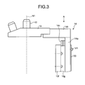
- FIG. 3 is a side view schematically illustrating a configuration of the main parts of the microscope according to the embodiment of the present invention.
- FIG. 4 is a partial cross-sectional view in the direction of arrow A in FIG. 3 ;
- FIG. 5 is a perspective view schematically illustrating a configuration of main parts of a microscope according to a first modification of the embodiment of the present invention.
- FIG. 6 is a perspective view schematically illustrating a configuration of main parts of a microscope according to a second modification of the embodiment of the present invention.
- FIG. 1 is a partial cross-sectional view schematically illustrating an overall configuration of a microscope 1 according to the embodiment.
- the microscope 1 includes a microscope frame 10 (microscope main body), which serves as a base of the microscope 1 and in which an optical system is disposed.
- the microscope frame 10 includes, for example, a stage 11 for placing a specimen S; a revolver 13 for holding a plurality of objective lenses 12 with different magnifications such that the objective lenses 12 can be replaced with respect to the specimen S; a focusing mechanism 14 that supports the revolver 13 , that is movable in the vertical direction along the optical axis of the objective lens 12 , and that adjusts the focus of the objective lens 12 ; a lens-barrel 16 on which an eyepiece 15 is mounted to observe an observation image formed by light emitted by the specimen S; and a dichroic mirror 17 that reflects light incident on the microscope frame 10 toward the specimen S and that transmits light emitted by the specimen S.
- the microscope 1 includes an electronic component 10 a including a control substrate for controlling the entire microscope 1 , a power supply, and the like inside the microscope frame 10 .
- a lamp house that emits illumination light for illuminating the specimen S on the stage 11 is appropriately attached to the microscope frame 10 , and the illumination light is applied to the specimen S by illumination optical systems M 1 and M 2 each being connected to the lamp house.
- the illumination optical system M 1 applies transmitted illumination light, which transmits to the specimen S.
- the illumination optical system M 2 applies epi-illumination light to the specimen S for illuminating the specimen S via the objective lens 12 and the dichroic mirror 17 .
- the illumination optical systems M 1 and M 2 form optical paths P 1 and P 2 , respectively.
- the microscope frame 10 includes an observation optical system M 3 (imaging optical system) that includes a tube lens 18 , which receives light transmitted through the specimen S via the illumination optical system N 1 or light reflected from the specimen S via the illumination optical system M 2 (hereinafter, the light will be described as observation light) and which forms an image by the received light, and that includes a plurality of mirrors 10 b for relaying the image formed by the tube lens 18 to the eyepiece 15 .
- the observation optical system M 3 forms an optical path P 3 .
- the observation optical system M 3 also includes a relay lens and the like in addition to the mirrors 10 b described above.
- the observation light that has become a parallel light flux by passing through the objective lens 12 is focused by passing through the tube lens 18 , and enters the lens-barrel 16 via the mirrors 10 b and the relay lens.
- the microscope frame 10 includes a base part 10 c that extends in the front-back direction, a rear wall part 10 d that extends upward from a rear edge portion of the base part 10 c , and a front wall part 10 e that extends upward from a front edge portion of the base part 10 c such that the microscope frame 10 has an approximately concave shape in the side view.
- the microscope frame 10 supports the stage 11 at the upper ends of the rear wall part 10 d and the front wall part 10 e .
- An area for arranging the objective lens 12 (the revolver 13 ) and the dichroic mirror 17 is defined between the rear wall part 10 d and the front wall part 10 e.
- An upper surface and a lower surface of the stage 11 are flat plate-shaped bodies, and the specimen S is placed on the upper surface.
- An aperture (through hole), which is small enough to keep the specimen S from falling through, is formed at around the center of the stage 11 so as to transmit the epi-illumination light or the observation light from the specimen S.
- the revolver 13 is rotatable and can be moved up and down by the focusing mechanism 14 .
- a plurality of the objective lenses 12 with different magnifications can be mounted on the revolver 13 .
- One of the objective lenses 12 mounted on the revolver 13 is located on the optical axis (for example, a straight line corresponding to the optical path P 1 ).
- FIG. 2 is a perspective view schematically illustrating a configuration of the focusing mechanism 14 of the microscope 1 according to the embodiment.
- FIG. 3 is a side view schematically illustrating the configuration of the focusing mechanism 14 of the microscope 1 according to the embodiment.
- FIG. 4 is a partial cross-sectional view in the direction of arrow A in FIG. 3 .
- the focusing mechanism 14 is used to adjust the focus of the objective lens 12 to the specimen S.
- the revolver 13 is moved up and down to adjust the focus of the objective lens 12 on the revolver 13 to the specimen S.
- the focusing mechanism 14 is disposed on the microscope frame 10 and attached to a fixing part 10 f extending in the extending direction of the rear wall part 10 d.
- the fixing part 10 f is disposed so as not to contact with the illumination optical system M 2 .
- Two columnar fixing-side guide members 10 g are provided on the fixing part 10 f and fixed with screws at positions so as to sandwich the focusing mechanism 14 .
- a metal made mostly of aluminum (including aluminum alloy) is used for the fixing part 10 f.
- the focusing mechanism 14 includes a plate-shaped base part 14 a , a revolver support part 14 b , and two columnar moving-side guide members 14 c .
- the revolver support part 14 b continues into one end of the base part 14 a , extends in a direction perpendicular to the principal surface of the base part 14 a , and supports the revolver 13 at an end portion in the extending direction.
- the two columnar moving-side guide members 14 c are fixed with screws to the principal surface of the base part 14 a , respectively connected to the fixing-side guide members 10 g so as to form pairs, and guide the movement of the focusing mechanism 14 .
- the base part 14 a supports the revolver 13 via the revolver support part 14 b .
- Metal made mostly of aluminum (including aluminum alloy) is used for the base part 14 a and the revolver support part 14 b in order to reduce weight.
- Steel or iron with high rigidity is used for the moving-side guide members 14 c and the fixing-side guide members 10 g in view of oscillation that occurs when observation is performed or when the base part 14 a is moved.
- the fixing-side guide members 10 g are connected to outer surfaces of the moving-side guide members 14 c .
- the fixing-side guide members 10 g and the moving-side guide members 14 c are connected to each other via ball guides 10 h arranged along the extending direction of the fixing-side guide members 10 g .
- the moving-side guide members 14 c can move along the extending direction of the fixing-side guide members 10 g .
- a driving force for the movement is transmitted to the moving-side guide members 14 c by a not-shown drive transmission mechanism (for example, rack and pinion).
- the drive transmission mechanism may directly receive the amount of the movement according to the amount of rotation of a focus handle or may electrically receive the amount of the movement according to an operation of pressing an input button or the like.
- a plate member 20 that is made of metal (steel) composed mostly of iron and that has approximately the same length as the moving-side guide members 14 c is disposed.
- the plate member 20 is attached with screws V 1 such that a principal surface of the plate member 20 and the principal surface of the base part 14 a come into contact with each other.
- the plate member 20 is in contact with the principal surface of the base part 14 a without space.
- the plate member 20 is arranged on the principal surface of the base part 14 a at a position corresponding to a middle position between the two moving-side guide members 14 c.
- the inverted microscope having the above-described configuration in the case of transmitted-light illumination, when transmitted illumination light from the illumination optical system M 1 is applied to the specimen S on the stage 11 , light transmitted through the specimen S enters the objective lens 12 , is focused by the imaging optical system M 3 , and is visually observed by an observer through the eyepiece 15 via the mirrors 10 b .
- the transmitted light observation is used to perform a bright field observation, a phase contrast observation, a differential interference observation, and the like.
- the dichroic mirror 17 is not mounted.
- a wavelength of epi-illumination light from the illumination optical system M 2 is selected by an excitation filter (not shown) or the like, and the epi-illumination light is reflected by the dichroic mirror 17 toward the objective lens 12 .
- an excitation filter not shown
- the epi-illumination light is reflected by the dichroic mirror 17 toward the objective lens 12 .
- the illumination light reflected by the dichroic mirror 17 is illuminated onto the specimen S on the stage 11 via the objective lens 12 , a fluorescent dye or fluorescent protein in a cell of the specimen S for example is excited and fluorescent light is emitted.
- the emitted fluorescent light is incident on the objective lens 12 , and the light is transmitted through the dichroic mirror 17 , focused by the imaging optical system M 3 , and visually viewed by an observer through the eyepiece 15 via the mirrors 10 b.
- the microscope frame or the focusing mechanism that fix the guides may thermally expands due to a heat source of the microscope 1 (e.g., heat generated by a light source or an electronic component of the illumination optical system) or due to a change in the temperature of a surrounding environment.
- a heat source of the microscope 1 e.g., heat generated by a light source or an electronic component of the illumination optical system
- the amount of expansion and contraction due to the thermal expansion differs, resulting in warp deformation.
- the revolver support part 14 b is inclined due to the warpage of the base part 14 a , the focus may be deviated and an optical axis N 1 of the objective lens 12 may be inclined.
- the moving-side guide members 14 c and the plate member 20 that are made of metal composed mostly of, for example, iron with a smaller linear expansion coefficient than that of aluminum are arranged so as to sandwich the base part 14 a that is made of aluminum, it is possible to prevent warpage of the base part 14 a .
- a plane parallel to the principal surface of the base part 14 a is an XY plane, it is possible to prevent warpage in the Z direction perpendicular to the XY plane. Therefore, it is possible to prevent the optical axis N 1 of the objective lens 12 from being inclined due to the warpage of the base part 14 a.
- the moving-side guide members 14 c and the plate member 20 that are made of a material with a smaller linear expansion coefficient than that of the base part 14 a are arranged on the surfaces of the base part 14 a so as to sandwich the base part 14 a . Therefore, it is possible to maintain the optical performance of the microscope 1 without influence of thermal expansion of each part.
- the base part 14 a is made of aluminum and the moving-side guide members 14 c and the plate member 20 are made of metal (steel) composed mostly of iron.
- metal steel
- any materials may be applicable as long as the linear expansion coefficient of a material of the moving-side guide members 14 c and the plate member 20 differs from the linear expansion coefficient of a material of the base part 14 a and as long as warpage can be prevented.
- the above-described materials with different linear expansion coefficients include the same type (category) of materials with different linear expansion coefficients, in addition to different types of materials such as aluminum and steel as explained above.
- A5052 and ADC12 are the same types of aluminum alloys
- the linear expansion coefficient of A5052 is about 24 ⁇ 10 ⁇ 6 and the linear expansion coefficient of ADC12 is about 21 ⁇ 10 ⁇ 6 . Therefore, A5052 and ADC12 that are aluminum alloys can be employed as materials with different linear expansion coefficients that differ from each other by about 10%.
- the moving-side guide members 14 c and the plate member 20 may be made of different materials from one another within a range as described above.
- the present invention is not limited thereto. It is sufficient that the plate member 20 has a length enough to prevent the warp deformation. Moreover, while the plate member 20 is disposed at the middle position between the moving-side guide members 14 c , the present invention is not limited thereto. It is preferable to dispose the plate member 20 at an appropriate position between the moving-side guide members 14 c to further prevent the warp deformation.
- the plate member 20 is arranged on one of the principal surfaces of the base part 14 a opposite to the other principal surface on which the moving-side guide members 14 c are arranged, the plate member 20 may be arranged between the moving-side guide members 14 c on the other principal surface where the moving-side guide members 14 c are arranged.
- the moving-side guide members 14 c are two columnar members, a single plate-shaped member may be employed.
- the plate member 20 is arranged on one of the principal surfaces of the base part 14 a opposite to the other principal surface on which the moving-side guide members 14 c are arranged.
- FIG. 5 is a perspective view schematically illustrating a configuration of main parts of the microscope 1 according to a first modification of the embodiment.
- the same components as those described in FIG. 2 etc. are denoted by the same reference numerals and symbols.
- the principal surface of the plate member 20 has a rectangular shape.
- a plate member 21 may be set according to a load applied to the base part 14 a , the center of gravity of the base part 14 a , or a warping direction.
- the plate member 21 is made of metal (steel) composed mostly of iron, for example.
- the plate member 21 illustrated in FIG. 5 has a stepped shape in which one corner of a rectangular area is notched along lines parallel to respective sides. Specifically, assuming that the principal surface of the base part 14 a is an XY plane, the lengths of both ends in each of the X direction and the Y direction differ from each other when the plate member 21 is arranged on the base part 14 a . With the differences between the lengths, it becomes possible to reduce the amount of complex warpage in the X and Y directions.
- the lengths of both ends in the X and Y directions can be set according to a load applied to the base part 14 a by the revolver 13 , the center of gravity of the base part 14 a , or the warping direction.
- FIG. 6 is a perspective view schematically illustrating a configuration of main parts of the microscope 1 according to a second modification of the embodiment.
- the same components as those explained in FIG. 2 etc. are denoted by the same reference numerals and symbols.
- the lengths of both ends in each of the X and Y directions are made different in one plate member.
- the plate members 22 a and 22 b are made of metal (steel) composed mostly of iron, for example.
- the plate members 22 a and 22 b illustrated in FIG. 6 at least longitudinal lengths are different from each other. Specifically, when the plate members 22 a and 22 b are arranged at respective specified positions on the base part 14 a , arrangement areas in the longitudinal direction differ from each other. With this difference in the arrangement areas, it is possible to reduce the amount of complex warpage in the X and Y directions if the principal surface of the base part 14 a is an XY plane.
- the lengths of both ends in the X and Y directions can be changed according to a load applied to the base part 14 a by the revolver 13 , the center of gravity of the base part 14 a , or the warping direction.
- the plate member may be arranged on a plane where the moving-side guide members 14 c are arranged, a plane where the fixing-side guide members 10 g attached to the fixing part 10 f are arranged, or a plane opposite to the plane where the fixing-side guide members 10 g are arranged, instead of arranging the plate members 22 a and 22 b on a plane of the base part 14 a opposite to the plane where the moving-side guide members 14 c are arranged.
- a sliding revolver can be employed instead of the rotary revolver 13 .
- the sliding revolver can arrange the desired objective lens 12 to a position below the specimen S via a slider that is slideable in a direction perpendicular to the optical axis N 1 of the objective lens 12 .
- the plate member is arranged at the same position as described above.
- the focusing mechanism 14 supports the revolver 13 .
- the focusing mechanism 14 may support the stage 11 .
- the present invention may be applied to any apparatuses including a focusing mechanism.
- the present invention may be applied to an upright microscope or an imaging apparatus such as a video microscope that includes an objective lens for enlarging a specimen and that has functions to capture an image of the specimen via the objective lens and to display the image.
- the microscope focusing mechanism according to the embodiment of the present invention is useful to maintain the optical performance of the microscope without influence of thermal expansion.
Landscapes
- Physics & Mathematics (AREA)
- Chemical & Material Sciences (AREA)
- Analytical Chemistry (AREA)
- General Physics & Mathematics (AREA)
- Optics & Photonics (AREA)
- Microscoopes, Condenser (AREA)
Abstract
Description
Claims (4)
Applications Claiming Priority (2)
| Application Number | Priority Date | Filing Date | Title |
|---|---|---|---|
| JP2012147886A JP6009838B2 (en) | 2012-06-29 | 2012-06-29 | Microscope focusing mechanism |
| JP2012-147886 | 2012-06-29 |
Publications (2)
| Publication Number | Publication Date |
|---|---|
| US20140002896A1 US20140002896A1 (en) | 2014-01-02 |
| US9405113B2 true US9405113B2 (en) | 2016-08-02 |
Family
ID=49777870
Family Applications (1)
| Application Number | Title | Priority Date | Filing Date |
|---|---|---|---|
| US13/926,934 Active 2033-11-16 US9405113B2 (en) | 2012-06-29 | 2013-06-25 | Microscope focusing mechanism with movable components formed of materials having different linear expansion coefficients |
Country Status (2)
| Country | Link |
|---|---|
| US (1) | US9405113B2 (en) |
| JP (1) | JP6009838B2 (en) |
Families Citing this family (3)
| Publication number | Priority date | Publication date | Assignee | Title |
|---|---|---|---|---|
| JP6560523B2 (en) | 2015-04-08 | 2019-08-14 | キヤノン株式会社 | Stage device and microscope |
| US10671510B1 (en) | 2016-06-24 | 2020-06-02 | Intuit, Inc. | Techniques for evaluating collected build metrics during a software build process |
| CN110996002B (en) * | 2019-12-16 | 2021-08-24 | 深圳市瑞图生物技术有限公司 | Microscope focusing method, device, computer equipment and storage medium |
Citations (5)
| Publication number | Priority date | Publication date | Assignee | Title |
|---|---|---|---|---|
| JPH06109963A (en) | 1992-09-25 | 1994-04-22 | Olympus Optical Co Ltd | Focusing mechanism for microscope |
| JPH06222275A (en) | 1993-01-21 | 1994-08-12 | Olympus Optical Co Ltd | Focusing guide mechanism for microscope |
| JPH0755512A (en) | 1993-08-19 | 1995-03-03 | Mitaka Koki Co Ltd | Supporting base of measuring instrument |
| JPH09120030A (en) | 1995-08-16 | 1997-05-06 | Leica Mikroskopie & Syst Gmbh | Focus stabilizer for microscope |
| US20070157712A1 (en) * | 2005-12-19 | 2007-07-12 | Jeol Ltd. | Micromotion device and scanning probe microscope |
-
2012
- 2012-06-29 JP JP2012147886A patent/JP6009838B2/en active Active
-
2013
- 2013-06-25 US US13/926,934 patent/US9405113B2/en active Active
Patent Citations (6)
| Publication number | Priority date | Publication date | Assignee | Title |
|---|---|---|---|---|
| JPH06109963A (en) | 1992-09-25 | 1994-04-22 | Olympus Optical Co Ltd | Focusing mechanism for microscope |
| JPH06222275A (en) | 1993-01-21 | 1994-08-12 | Olympus Optical Co Ltd | Focusing guide mechanism for microscope |
| JPH0755512A (en) | 1993-08-19 | 1995-03-03 | Mitaka Koki Co Ltd | Supporting base of measuring instrument |
| JPH09120030A (en) | 1995-08-16 | 1997-05-06 | Leica Mikroskopie & Syst Gmbh | Focus stabilizer for microscope |
| US5703715A (en) | 1995-08-16 | 1997-12-30 | Leica Mikroskopie Und Systeme Gmbh | Device for stabilizing the focus of a microscope |
| US20070157712A1 (en) * | 2005-12-19 | 2007-07-12 | Jeol Ltd. | Micromotion device and scanning probe microscope |
Non-Patent Citations (1)
| Title |
|---|
| Japanese Office Action (and English translation thereof) dated Jun. 7, 2016, issued in counterpart Japanese Application No. 2012-147886. |
Also Published As
| Publication number | Publication date |
|---|---|
| JP2014010354A (en) | 2014-01-20 |
| US20140002896A1 (en) | 2014-01-02 |
| JP6009838B2 (en) | 2016-10-19 |
Similar Documents
| Publication | Publication Date | Title |
|---|---|---|
| JP5047669B2 (en) | Scanning confocal microscope | |
| US9041940B2 (en) | Three-dimensional shape measuring apparatus | |
| JP2005331888A (en) | Fluorescence microscope | |
| JP6879310B2 (en) | Microscope device | |
| US20220091404A1 (en) | A Compact Fluorescence Microscope and a Cell Monitoring System | |
| US9405113B2 (en) | Microscope focusing mechanism with movable components formed of materials having different linear expansion coefficients | |
| JP5142315B2 (en) | Microscope and observation method thereof | |
| US9019600B2 (en) | Microscope system | |
| JPH10339845A (en) | Monitor observation type microscope | |
| JP6987493B2 (en) | microscope | |
| JP2002267940A (en) | Inverted microscope system | |
| JPH0651204A (en) | System microscope | |
| JP2002048978A (en) | Objective lens unit, optical device having objective lens unit and observation method using the optical device | |
| JPH10253895A (en) | Revolver for microscope and microscope | |
| US9052509B2 (en) | Microscope system including detachable stage and detachable transmitted illumination optical system | |
| US9250433B2 (en) | Microscope system with plural attachable/detachable objective lens units | |
| US20180045940A1 (en) | Microscope and optical unit | |
| US9140886B2 (en) | Inverted microscope including a control unit configured to synchronize a switching operation between absorption filters with a switching operation between excitation filters | |
| US7936502B2 (en) | Microscope | |
| JP2013213855A (en) | Stage structure and inverted type microscope | |
| JP5512122B2 (en) | Scanning laser microscope and sub-assembly for non-descanned detection | |
| JP4046525B2 (en) | Inverted microscope | |
| JP6203102B2 (en) | Inverted microscope device | |
| JP5581752B2 (en) | Autofocus optical device, microscope | |
| JP2009116054A (en) | Optical device and microscope |
Legal Events
| Date | Code | Title | Description |
|---|---|---|---|
| AS | Assignment |
Owner name: OLYMPUS CORPORATION, JAPAN Free format text: ASSIGNMENT OF ASSIGNORS INTEREST;ASSIGNORS:AMANO, YUSUKE;KAMOMAE, TAKAYOSHI;KATAOKA, YUICHI;REEL/FRAME:030684/0830 Effective date: 20130529 |
|
| FEPP | Fee payment procedure |
Free format text: PAYOR NUMBER ASSIGNED (ORIGINAL EVENT CODE: ASPN); ENTITY STATUS OF PATENT OWNER: LARGE ENTITY |
|
| STCF | Information on status: patent grant |
Free format text: PATENTED CASE |
|
| AS | Assignment |
Owner name: OLYMPUS CORPORATION, JAPAN Free format text: CHANGE OF ADDRESS;ASSIGNOR:OLYMPUS CORPORATION;REEL/FRAME:039708/0151 Effective date: 20160401 |
|
| MAFP | Maintenance fee payment |
Free format text: PAYMENT OF MAINTENANCE FEE, 4TH YEAR, LARGE ENTITY (ORIGINAL EVENT CODE: M1551); ENTITY STATUS OF PATENT OWNER: LARGE ENTITY Year of fee payment: 4 |
|
| AS | Assignment |
Owner name: EVIDENT CORPORATION, JAPAN Free format text: ASSIGNMENT OF ASSIGNORS INTEREST;ASSIGNOR:OLYMPUS CORPORATION;REEL/FRAME:062492/0267 Effective date: 20221024 Owner name: EVIDENT CORPORATION, JAPAN Free format text: ASSIGNMENT OF ASSIGNOR'S INTEREST;ASSIGNOR:OLYMPUS CORPORATION;REEL/FRAME:062492/0267 Effective date: 20221024 |
|
| MAFP | Maintenance fee payment |
Free format text: PAYMENT OF MAINTENANCE FEE, 8TH YEAR, LARGE ENTITY (ORIGINAL EVENT CODE: M1552); ENTITY STATUS OF PATENT OWNER: LARGE ENTITY Year of fee payment: 8 |