US9404434B2 - Universal solenoid driver - Google Patents
Universal solenoid driver Download PDFInfo
- Publication number
- US9404434B2 US9404434B2 US14/151,484 US201414151484A US9404434B2 US 9404434 B2 US9404434 B2 US 9404434B2 US 201414151484 A US201414151484 A US 201414151484A US 9404434 B2 US9404434 B2 US 9404434B2
- Authority
- US
- United States
- Prior art keywords
- solenoid
- control unit
- control
- driver
- sensor
- Prior art date
- Legal status (The legal status is an assumption and is not a legal conclusion. Google has not performed a legal analysis and makes no representation as to the accuracy of the status listed.)
- Active, expires
Links
- 230000002093 peripheral effect Effects 0.000 claims abstract description 37
- 238000000034 method Methods 0.000 claims description 49
- 239000000446 fuel Substances 0.000 claims description 35
- 230000005540 biological transmission Effects 0.000 claims description 26
- 238000002347 injection Methods 0.000 claims description 16
- 239000007924 injection Substances 0.000 claims description 16
- 238000005259 measurement Methods 0.000 description 15
- 238000010586 diagram Methods 0.000 description 13
- 238000003745 diagnosis Methods 0.000 description 12
- 238000004891 communication Methods 0.000 description 10
- 230000011664 signaling Effects 0.000 description 9
- 230000001360 synchronised effect Effects 0.000 description 8
- 230000008859 change Effects 0.000 description 6
- 230000009471 action Effects 0.000 description 4
- 238000012545 processing Methods 0.000 description 4
- 230000008878 coupling Effects 0.000 description 3
- 238000010168 coupling process Methods 0.000 description 3
- 238000005859 coupling reaction Methods 0.000 description 3
- 230000006870 function Effects 0.000 description 3
- 230000004044 response Effects 0.000 description 3
- 230000001133 acceleration Effects 0.000 description 1
- 238000003491 array Methods 0.000 description 1
- 230000006399 behavior Effects 0.000 description 1
- 230000001427 coherent effect Effects 0.000 description 1
- 238000013461 design Methods 0.000 description 1
- 230000005669 field effect Effects 0.000 description 1
- 230000004907 flux Effects 0.000 description 1
- 238000004519 manufacturing process Methods 0.000 description 1
- 239000000463 material Substances 0.000 description 1
- 229910044991 metal oxide Inorganic materials 0.000 description 1
- 150000004706 metal oxides Chemical class 0.000 description 1
- 230000004048 modification Effects 0.000 description 1
- 238000012986 modification Methods 0.000 description 1
- 230000003287 optical effect Effects 0.000 description 1
- 239000004065 semiconductor Substances 0.000 description 1
Images


Classifications
-
- F—MECHANICAL ENGINEERING; LIGHTING; HEATING; WEAPONS; BLASTING
- F02—COMBUSTION ENGINES; HOT-GAS OR COMBUSTION-PRODUCT ENGINE PLANTS
- F02D—CONTROLLING COMBUSTION ENGINES
- F02D41/00—Electrical control of supply of combustible mixture or its constituents
- F02D41/30—Controlling fuel injection
-
- F—MECHANICAL ENGINEERING; LIGHTING; HEATING; WEAPONS; BLASTING
- F02—COMBUSTION ENGINES; HOT-GAS OR COMBUSTION-PRODUCT ENGINE PLANTS
- F02D—CONTROLLING COMBUSTION ENGINES
- F02D41/00—Electrical control of supply of combustible mixture or its constituents
- F02D41/02—Circuit arrangements for generating control signals
- F02D41/14—Introducing closed-loop corrections
- F02D41/1401—Introducing closed-loop corrections characterised by the control or regulation method
-
- F—MECHANICAL ENGINEERING; LIGHTING; HEATING; WEAPONS; BLASTING
- F16—ENGINEERING ELEMENTS AND UNITS; GENERAL MEASURES FOR PRODUCING AND MAINTAINING EFFECTIVE FUNCTIONING OF MACHINES OR INSTALLATIONS; THERMAL INSULATION IN GENERAL
- F16D—COUPLINGS FOR TRANSMITTING ROTATION; CLUTCHES; BRAKES
- F16D48/00—External control of clutches
- F16D48/06—Control by electric or electronic means, e.g. of fluid pressure
- F16D48/062—Control by electric or electronic means, e.g. of fluid pressure of a clutch system with a plurality of fluid actuated clutches
-
- F—MECHANICAL ENGINEERING; LIGHTING; HEATING; WEAPONS; BLASTING
- F02—COMBUSTION ENGINES; HOT-GAS OR COMBUSTION-PRODUCT ENGINE PLANTS
- F02D—CONTROLLING COMBUSTION ENGINES
- F02D41/00—Electrical control of supply of combustible mixture or its constituents
- F02D41/02—Circuit arrangements for generating control signals
- F02D41/14—Introducing closed-loop corrections
- F02D41/1401—Introducing closed-loop corrections characterised by the control or regulation method
- F02D2041/1413—Controller structures or design
- F02D2041/1418—Several control loops, either as alternatives or simultaneous
- F02D2041/1419—Several control loops, either as alternatives or simultaneous the control loops being cascaded, i.e. being placed in series or nested
-
- F—MECHANICAL ENGINEERING; LIGHTING; HEATING; WEAPONS; BLASTING
- F02—COMBUSTION ENGINES; HOT-GAS OR COMBUSTION-PRODUCT ENGINE PLANTS
- F02D—CONTROLLING COMBUSTION ENGINES
- F02D41/00—Electrical control of supply of combustible mixture or its constituents
- F02D41/20—Output circuits, e.g. for controlling currents in command coils
- F02D2041/202—Output circuits, e.g. for controlling currents in command coils characterised by the control of the circuit
- F02D2041/2048—Output circuits, e.g. for controlling currents in command coils characterised by the control of the circuit said control involving a limitation, e.g. applying current or voltage limits
-
- F—MECHANICAL ENGINEERING; LIGHTING; HEATING; WEAPONS; BLASTING
- F02—COMBUSTION ENGINES; HOT-GAS OR COMBUSTION-PRODUCT ENGINE PLANTS
- F02D—CONTROLLING COMBUSTION ENGINES
- F02D41/00—Electrical control of supply of combustible mixture or its constituents
- F02D41/20—Output circuits, e.g. for controlling currents in command coils
- F02D2041/202—Output circuits, e.g. for controlling currents in command coils characterised by the control of the circuit
- F02D2041/2058—Output circuits, e.g. for controlling currents in command coils characterised by the control of the circuit using information of the actual current value
- F02D2041/2062—Output circuits, e.g. for controlling currents in command coils characterised by the control of the circuit using information of the actual current value the current value is determined by simulation or estimation
-
- F—MECHANICAL ENGINEERING; LIGHTING; HEATING; WEAPONS; BLASTING
- F02—COMBUSTION ENGINES; HOT-GAS OR COMBUSTION-PRODUCT ENGINE PLANTS
- F02D—CONTROLLING COMBUSTION ENGINES
- F02D41/00—Electrical control of supply of combustible mixture or its constituents
- F02D41/24—Electrical control of supply of combustible mixture or its constituents characterised by the use of digital means
- F02D41/26—Electrical control of supply of combustible mixture or its constituents characterised by the use of digital means using computer, e.g. microprocessor
- F02D41/28—Interface circuits
- F02D2041/281—Interface circuits between sensors and control unit
-
- F—MECHANICAL ENGINEERING; LIGHTING; HEATING; WEAPONS; BLASTING
- F02—COMBUSTION ENGINES; HOT-GAS OR COMBUSTION-PRODUCT ENGINE PLANTS
- F02D—CONTROLLING COMBUSTION ENGINES
- F02D41/00—Electrical control of supply of combustible mixture or its constituents
- F02D41/24—Electrical control of supply of combustible mixture or its constituents characterised by the use of digital means
- F02D41/26—Electrical control of supply of combustible mixture or its constituents characterised by the use of digital means using computer, e.g. microprocessor
- F02D41/28—Interface circuits
- F02D2041/286—Interface circuits comprising means for signal processing
-
- F—MECHANICAL ENGINEERING; LIGHTING; HEATING; WEAPONS; BLASTING
- F02—COMBUSTION ENGINES; HOT-GAS OR COMBUSTION-PRODUCT ENGINE PLANTS
- F02D—CONTROLLING COMBUSTION ENGINES
- F02D2250/00—Engine control related to specific problems or objectives
- F02D2250/12—Timing of calculation, i.e. specific timing aspects when calculation or updating of engine parameter is performed
-
- F—MECHANICAL ENGINEERING; LIGHTING; HEATING; WEAPONS; BLASTING
- F02—COMBUSTION ENGINES; HOT-GAS OR COMBUSTION-PRODUCT ENGINE PLANTS
- F02D—CONTROLLING COMBUSTION ENGINES
- F02D41/00—Electrical control of supply of combustible mixture or its constituents
- F02D41/20—Output circuits, e.g. for controlling currents in command coils
-
- F—MECHANICAL ENGINEERING; LIGHTING; HEATING; WEAPONS; BLASTING
- F02—COMBUSTION ENGINES; HOT-GAS OR COMBUSTION-PRODUCT ENGINE PLANTS
- F02D—CONTROLLING COMBUSTION ENGINES
- F02D41/00—Electrical control of supply of combustible mixture or its constituents
- F02D41/24—Electrical control of supply of combustible mixture or its constituents characterised by the use of digital means
- F02D41/26—Electrical control of supply of combustible mixture or its constituents characterised by the use of digital means using computer, e.g. microprocessor
-
- F—MECHANICAL ENGINEERING; LIGHTING; HEATING; WEAPONS; BLASTING
- F16—ENGINEERING ELEMENTS AND UNITS; GENERAL MEASURES FOR PRODUCING AND MAINTAINING EFFECTIVE FUNCTIONING OF MACHINES OR INSTALLATIONS; THERMAL INSULATION IN GENERAL
- F16D—COUPLINGS FOR TRANSMITTING ROTATION; CLUTCHES; BRAKES
- F16D27/00—Magnetically- or electrically- actuated clutches; Control or electric circuits therefor
- F16D2027/002—Electric or electronic circuits relating to actuation of electromagnetic clutches
-
- F—MECHANICAL ENGINEERING; LIGHTING; HEATING; WEAPONS; BLASTING
- F16—ENGINEERING ELEMENTS AND UNITS; GENERAL MEASURES FOR PRODUCING AND MAINTAINING EFFECTIVE FUNCTIONING OF MACHINES OR INSTALLATIONS; THERMAL INSULATION IN GENERAL
- F16D—COUPLINGS FOR TRANSMITTING ROTATION; CLUTCHES; BRAKES
- F16D48/00—External control of clutches
- F16D48/02—Control by fluid pressure
- F16D2048/0221—Valves for clutch control systems; Details thereof
-
- F—MECHANICAL ENGINEERING; LIGHTING; HEATING; WEAPONS; BLASTING
- F16—ENGINEERING ELEMENTS AND UNITS; GENERAL MEASURES FOR PRODUCING AND MAINTAINING EFFECTIVE FUNCTIONING OF MACHINES OR INSTALLATIONS; THERMAL INSULATION IN GENERAL
- F16D—COUPLINGS FOR TRANSMITTING ROTATION; CLUTCHES; BRAKES
- F16D2500/00—External control of clutches by electric or electronic means
- F16D2500/30—Signal inputs
- F16D2500/302—Signal inputs from the actuator
- F16D2500/3022—Current
-
- F—MECHANICAL ENGINEERING; LIGHTING; HEATING; WEAPONS; BLASTING
- F16—ENGINEERING ELEMENTS AND UNITS; GENERAL MEASURES FOR PRODUCING AND MAINTAINING EFFECTIVE FUNCTIONING OF MACHINES OR INSTALLATIONS; THERMAL INSULATION IN GENERAL
- F16D—COUPLINGS FOR TRANSMITTING ROTATION; CLUTCHES; BRAKES
- F16D2500/00—External control of clutches by electric or electronic means
- F16D2500/30—Signal inputs
- F16D2500/302—Signal inputs from the actuator
- F16D2500/3024—Pressure
-
- F—MECHANICAL ENGINEERING; LIGHTING; HEATING; WEAPONS; BLASTING
- F16—ENGINEERING ELEMENTS AND UNITS; GENERAL MEASURES FOR PRODUCING AND MAINTAINING EFFECTIVE FUNCTIONING OF MACHINES OR INSTALLATIONS; THERMAL INSULATION IN GENERAL
- F16D—COUPLINGS FOR TRANSMITTING ROTATION; CLUTCHES; BRAKES
- F16D2500/00—External control of clutches by electric or electronic means
- F16D2500/30—Signal inputs
- F16D2500/302—Signal inputs from the actuator
- F16D2500/3026—Stroke
-
- F—MECHANICAL ENGINEERING; LIGHTING; HEATING; WEAPONS; BLASTING
- F16—ENGINEERING ELEMENTS AND UNITS; GENERAL MEASURES FOR PRODUCING AND MAINTAINING EFFECTIVE FUNCTIONING OF MACHINES OR INSTALLATIONS; THERMAL INSULATION IN GENERAL
- F16D—COUPLINGS FOR TRANSMITTING ROTATION; CLUTCHES; BRAKES
- F16D2500/00—External control of clutches by electric or electronic means
- F16D2500/30—Signal inputs
- F16D2500/302—Signal inputs from the actuator
- F16D2500/3028—Voltage
-
- F—MECHANICAL ENGINEERING; LIGHTING; HEATING; WEAPONS; BLASTING
- F16—ENGINEERING ELEMENTS AND UNITS; GENERAL MEASURES FOR PRODUCING AND MAINTAINING EFFECTIVE FUNCTIONING OF MACHINES OR INSTALLATIONS; THERMAL INSULATION IN GENERAL
- F16D—COUPLINGS FOR TRANSMITTING ROTATION; CLUTCHES; BRAKES
- F16D2500/00—External control of clutches by electric or electronic means
- F16D2500/30—Signal inputs
- F16D2500/306—Signal inputs from the engine
- F16D2500/3063—Engine fuel flow rate
-
- F—MECHANICAL ENGINEERING; LIGHTING; HEATING; WEAPONS; BLASTING
- F16—ENGINEERING ELEMENTS AND UNITS; GENERAL MEASURES FOR PRODUCING AND MAINTAINING EFFECTIVE FUNCTIONING OF MACHINES OR INSTALLATIONS; THERMAL INSULATION IN GENERAL
- F16D—COUPLINGS FOR TRANSMITTING ROTATION; CLUTCHES; BRAKES
- F16D2500/00—External control of clutches by electric or electronic means
- F16D2500/70—Details about the implementation of the control system
- F16D2500/704—Output parameters from the control unit; Target parameters to be controlled
- F16D2500/70422—Clutch parameters
- F16D2500/70426—Clutch slip
-
- F—MECHANICAL ENGINEERING; LIGHTING; HEATING; WEAPONS; BLASTING
- F16—ENGINEERING ELEMENTS AND UNITS; GENERAL MEASURES FOR PRODUCING AND MAINTAINING EFFECTIVE FUNCTIONING OF MACHINES OR INSTALLATIONS; THERMAL INSULATION IN GENERAL
- F16D—COUPLINGS FOR TRANSMITTING ROTATION; CLUTCHES; BRAKES
- F16D2500/00—External control of clutches by electric or electronic means
- F16D2500/70—Details about the implementation of the control system
- F16D2500/706—Strategy of control
- F16D2500/7061—Feed-back
Definitions
- the invention relates to solenoids, and more particularly, but without limitation to solenoids used in automotive engine systems.
- Automatic systems such as vehicle transmissions, and fuel injection systems generally include a number of solenoids that are actuated to control those systems.
- a driver circuit actuates solenoids to engage and disengage hydraulically controlled clutches. By selectively engaging different clutches or combinations of clutches within the automotive transmission, a transmission control system may select a gear ratio for the transmission.
- a driver circuit may actuate solenoids that control fuel injectors. The fuel injectors release fuel into the cylinders of the engine.
- the driver IC includes first and second control units that each drive a solenoid that is coupled the first or second control unit.
- the first and second control units are communicatively coupled with at least one sensor of the automotive system, and to each other via a peripheral bus.
- the first and second control units, the solenoids, and the at least one sensor form a first, inner control loop.
- the first and second control units of the driver IC are also communicatively coupled with a microcontroller.
- the first and second control units and the microcontroller form a second, outer control loop. Based on sensor data, messages received from the first and second control units, the microcontroller, and electrical parameters of the solenoids, the first and second control units may actuate the first and second solenoids.
- the control units generate and receive control signals based on received signals, sensor data, and electrical parameters of the solenoids.
- the first and second control units may send messages to each other via a peripheral bus that communicatively couples the first and second control units.
- this disclosure is directed to a device comprising a driver IC comprising a first control unit and a second control unit.
- the device further includes a first solenoid that is electrically coupled to the first control unit, a second solenoid that is electrically coupled to the second control unit, at least one sensor, a clock that synchronizes a microcontroller and the driver IC, and a peripheral bus that communicatively couples the first control unit, the second control unit.
- the microcontroller and the driver IC form an outer control loop that actuates the first solenoid and the second solenoid, and the first control unit, the second control unit, and the at least one sensor form an inner control loop that controls the first solenoid and the second solenoid.
- this disclosure is directed to a method comprising receiving, from a microcontroller by a driver IC that includes a first control unit configured to control a first solenoid and a second control unit configured to control a second solenoid driver, a first feedback signal generated via a first control loop that comprises the microcontroller, the first control unit, and the second control unit.
- the method further includes receiving, by at least one of the first control unit and the second control unit, a second feedback signal generated via a second control loop that comprises the first control unit, the second control unit, and at least one sensor, and generating, by at least one of the microcontroller, the first control unit, and the second control unit based on at least one of the first feedback signal and the second feedback signal, a signal that causes one of the first control unit and the second control unit to actuate one of the first solenoid and the second solenoid.
- FIG. 1 is a block diagram illustrating a driver integrated circuit (IC) in an automotive system in accordance with one or more examples of this disclosure.
- IC driver integrated circuit
- FIG. 2 is a block diagram illustrating a driver integrated circuit in accordance with the techniques of this disclosure.
- FIG. 3 is an example of a current profile in accordance with the techniques of this disclosure.
- FIG. 4 is an example of a current profile in accordance with the techniques of this disclosure.
- FIG. 5 illustrates a signaling diagram when the microcontroller and the driver IC are operating in a closed loop control configuration in accordance with the techniques of this disclosure.
- FIG. 6 illustrates a signaling diagram of a microcontroller and a driver integrated circuit operating in a split loop configuration in accordance with the techniques of this disclosure.
- FIG. 7 illustrates a signaling diagram of a microcontroller and a driver integrated circuit operating in a split loop configuration in accordance with the techniques of this disclosure.
- FIG. 8 illustrates a signaling diagram of a microcontroller and a driver integrated circuit operating in a split loop configuration in accordance with the techniques of this disclosure.
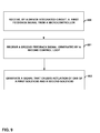
- FIG. 9 is a flowchart illustrating a method for actuating a solenoid in accordance with one or more techniques of this disclosure.
- this disclosure is directed toward an integrated circuit (IC) configured to actuate one or more solenoids in an automotive system, such as an automotive transmission, an automotive direct injection system, or other automotive system.
- the IC comprises first and second control units, which are each communicatively coupled with a solenoid.
- a control unit may drive a solenoid in order to control part of an automotive system, such as a clutch or a fuel injector.
- the drive IC may also be used with other types of vehicles as well as other non-vehicular systems.
- the first and second control units are coupled with sensors of the automotive system, as well as with each other.
- the first and second control units, the solenoids and the sensors form a first, inner control loop.
- the first and second control units are also communicatively coupled with a microcontroller.
- the first and second control units, and the microcontroller form an outer control loop.
- the inner and outer control loops send message and control signals, which may control the actuation of the solenoids by the first and second control units.
- FIG. 1 is a block diagram illustrating a driver integrated circuit (IC) in an automotive system in accordance with one or more examples of this disclosure.
- FIG. 1 illustrates an automotive control system 100 that includes driver integrated circuit (IC) 104 , microcontroller 102 , solenoids 108 A- 108 B (“solenoids 108 ”), and sensors 110 .
- Automotive control system 100 and driver IC 104 may be configured to actuate solenoids 108 based on one or more control signals in accordance with the techniques of this disclosure.
- Driver IC 104 further comprises a first control unit 106 A and a second control unit 106 B (collectively, “control unit 106 ”).
- Control units 106 are communicatively coupled with microcontroller 102 via a communication bus 112 .
- Communication bus 112 may comprise one or more asynchronous or synchronous busses, such as one or more asynchronous trigger buses.
- Control units 106 and control units 106 may comprise an outer control loop 116 .
- Control unit 106 A is also coupled with a first solenoid 108 A, and sensors 110 .
- Control unit 106 B is similarly coupled with a second solenoid 108 B and sensors 110 .
- Control unit 106 A and control unit 106 B are communicatively coupled with a peripheral bus 114 .
- Peripheral bus 114 may allow to transmission of data and messages, such as control signals, between control units 106 .
- Control units 106 , solenoids 108 , and sensors 110 comprise a second, inner control loop 118 .
- Automotive control system 100 may be configured to control a variety of different automotive systems.
- automotive control system 100 may control the actuation of solenoids 108 , which control the fuel injectors of an automotive direct injection system.
- Solenoids 108 may be driven by drivers in a high side and/or low-side driver configuration in some examples.
- Control units 106 may drive solenoids 108 , which may control fuel injectors of an automotive engine. In another example, control units 106 may drive solenoids 108 to control the engagement and disengagement of one or more clutches of an automotive transmission. In some examples, the drivers of solenoids 108 may be configured in a high side configuration for one of solenoids 108 , and a low side configuration for another one of solenoids 108 . In both the direct fuel injection case and the cases, microcontroller 102 , and control units 106 may be configured to actuate solenoids 108 in accordance with a current profile.
- Direct fuel injection and automotive transmission applications are just some of the applications of driver IC 104 , and should be considered as non-limiting examples.
- Control units 106 of driver IC 104 may be configured to control other aspects of an automotive engine, as well.
- techniques of this disclosure may also be directed to using driver IC to control an anti-lock braking solenoid, hydraulic cam-shaft actuation, or any other inductance-based solenoid.
- Using a single driver IC 104 to drive different solenoids for different applications may reduce overall system costs by simplifying system design, and may lower material costs due to the ability to produce higher volumes of a single driver IC 104 for multiple applications.
- control units 106 may actuate solenoids 108 based only on control signals and feedback signals from inner control loop 118 .
- control units 106 are communicatively coupled with one or more sensors 110 .
- Sensors 110 may comprise sensors, such as one or more voltage sensors, voltage acquisition measures, current sensors, current acquisition measures, position sensors, and/or pressure sensors, as well as sensors for detecting radio frequency (RF) coupling, and signal feedback.
- Control units 106 may also measure one or more electric and/or magnetic parameters of solenoids 108 .
- control unit 106 may measure inductance, resistance, current, voltage, flux, position, and/or other electro-magnetic, and/or mechanical parameters of solenoids 108 A.
- sensors 110 may comprise reading from one or more individual sensors, as well as the aforementioned parameters of solenoids 108 .
- Control units 106 may actuate solenoids 108 based on sensor data 108 and/or based on parameters of solenoids 108 and/or based on a current profile.
- current profiles are discussed in greater detail below with respect to FIGS. 3 and 4 .
- Control units 106 also may receive sensor data from sensors 110 via peripheral bus 114 .
- Peripheral bus 114 may comprise one or more serial and/or parallel busses.
- Control units 106 may detect parameters of solenoids 108 via an analog interface using one or more current measurement units (illustrated below with respect to FIG. 2 ). Based on captured data from sensors 110 and electrical parameters of solenoids 108 , which may comprise feedback and/or control signals of inner control loop 118 , control units 106 may actuate one or more of solenoids 110 based on a current profile.
- Peripheral bus 114 also communicatively couples control units 106 with each other and with a synchronization unit (illustrated in greater detail in FIG. 2 ).
- Control units 106 may communicate with each other and with the synchronization unit via peripheral bus 114 by transmitting one or more messages.
- the one or more messages may comprise control signals of inner control loop 118 , which when received by one of control units 106 , may cause the one of control units 106 to actuate one of solenoids 108 based on a current profile.
- Control units 106 may also actuate solenoid 108 based on one or more control signals of outer control loop 120 .
- outer control loop 116 includes microcontroller 102 , and control units 106 .
- Microcontroller 102 is communicatively coupled with control units 106 A via a trigger bus.
- the trigger bus may comprise an asynchronous bus.
- Microcontroller 102 may transmit a trigger pulse via trigger bus 112 to one or more of control units 106 .
- Control units 106 may receive the trigger pulse, and responsive to receiving the trigger pulse, may actuate one or more of solenoids 108 . In this manner, microcontroller 106 may control the actuation of solenoids 108 using control signals transmitted in outer control loop 116 .
- driver IC and control units 106 may receive a clock signal from microcontroller 102 .
- Driver IC 104 may function at a higher clock speed than the clock signal received from microcontroller 102 .
- driver IC may utilize a phase locked loop (PLL).
- FIGS. 5-8 illustrate the clock signals transmitted between microcontroller 102 and control units 106 , as well as synchronizing communications over peripheral bus 106 in greater detail.
- Control units 106 may be configured to operate in a “coherent actuation” mode, in which microcontroller 102 transmits a trigger signal to one or more of control units 106 in some examples.
- the trigger pulse is used by the control units to synchronized two or more drivers without the need for additional synchronization.
- control units 108 may indirectly synchronize with each other based on a programmable condition.
- control units 106 may operate in a feedback-based mode.
- one of control units 106 e.g. control unit 106 A
- One of control units 106 e.g. control unit 106 A, may perform relative actuation of two or more actuators based on direct communications of the drivers within control unit 106 A, as well as based on system feedback from sensors 110 .
- the system feedback from sensors 110 may include actuator position, acceleration, pressure, current, pressure, voltage, and radio frequency (RF) coupling feedback sensors.
- RF radio frequency
- Control units 106 may actuate solenoids 108 in response to a combination of control signals from both outer control loop 116 and inner control loop 118 , referred to as a “split control loop.”
- microcontroller 102 may transmit a trigger signal to one of control units 106 , e.g. control unit 106 A via the trigger bus of communication bus 112 .
- control unit 106 A may actuate solenoid 108 A based on a current profile.
- Control unit 106 B may receive a control signal from control unit 106 A responsive to control unit 106 A receiving the trigger signal and/or control unit 106 A actuating solenoid 106 A.
- control unit 106 B may actuate solenoid 108 B based on a current profile.
- a signaling diagram illustrating the actuation of a first solenoid based on a CPU trigger by a first control unit, and the actuation of a second solenoid by a second control unit responsive to receiving a message from the first control unit is illustrated in greater detail below with respect to FIG. 5 .
- a first control e.g. control unit 106 A
- system 100 may comprise a driver IC 104 comprising a first control unit 106 A and a second control unit 106 B.
- System 100 further includes solenoid 108 A, which includes a first solenoid coupled to first control unit 106 A, and a second solenoid 108 B, which is electrically coupled to second control unit 106 B.
- System 100 includes sensors 110 , which may comprise at least one sensor, a clock that synchronizes microcontroller 102 with driver IC 104 , peripheral bus 114 that communicatively couples first control unit 106 A and second control unit 106 B.
- Microcontroller 102 and driver IC form 104 form outer control loop 116 , which actuates the first solenoid 108 A and the second solenoid 108 B.
- the first control unit 106 A, second control unit 106 B, and at least one sensor of sensors 110 form an inner control loop 118 that control the first solenoid 108 A and the second solenoid 108 B.
- FIG. 2 is a block diagram illustrating a driver integrated circuit in accordance with the techniques of this disclosure.
- FIG. 2 illustrates the functional units of driver IC 104 .
- the functional units of driver IC 104 includes first control unit 106 A and second control unit 106 B (control units 106 ), common control unit 120 , synchronization unit 122 , a clock 124 , and sensor interface 126 .
- Driver IC 104 further may also include dither generator unit 128 A, and dither generator unit 128 B (dither generators 128 ), current measurement unit 130 A, current measurement unit 130 B (current measurement units 130 ), driver unit 132 A, driver unit 132 B (driver units 132 ), diagnosis unit 134 A, diagnosis unit 134 B (diagnosis units 134 ), and timer unit 136 .
- Dither generators 128 may only be present for transmission control applications, in some examples.
- Common control unit 120 generates common control signals to each of control unit 106 A and control unit 106 B.
- Common control signals may include common control signals for dither generator units 128 .
- Common control unit may generate the common control signals based data received from sensor interface 126 , as well as based on signals and data received from microcontroller 102 ( FIG. 1 ).
- Dither generator units 128 generate dither signals, which may comprise signals having small, random fluctuations.
- Dither generators 128 may add the dither signal to the signals generated by common control unit 120 .
- Dither signals may comprise signals that include random fluctuations and noise.
- dither generator units 128 may also be coupled to the output of current curve controllers of control unit 106 such that the dither signals that dither generator units 128 output is not combined or part of the signals generated by common control unit 120 .
- Each of current measurement units 130 may measure the current being applied to one of solenoids 108 , and may add the measured current value back to the signal generated by common control unit 120 as a form of feedback.
- control units 106 receive a common control unit signal, a dither signal, and a current measurement feedback signal as input, and may generate one or more output signals based on the input signals.
- the modules of FIG. 2 may also include a current profile generator.
- the current profile generator may generate and output a current profile in accordance with the examples illustrated in FIG. 4 , below.
- the current profile generator may generate the current profile based on a set of data points received from microcontroller 102 and/or that the current generator itself calculates.
- Control units 106 A and 106 B correspond to those of FIG. 1 .
- Control units 106 each may each include a central processing unit (CPU), memory, diagnostic interface, capture compare unit (CCU), and current curve controller (CCC).
- the CPU may comprise a reduced instruction set controller (RISC) CPU in some examples.
- the CPU may include one or more registers, which may include a status register.
- the CPU may include a bus arbiter/direct memory access (DMA) unit, which supports reading to and writing from the memory content of instruction memory and data memory at any time.
- the bus arbiter/DMA unit may also synchronize control of the CCU and the CCC.
- the CCCs of control unit 106 may be responsible for reading various electrical parameters, such as current, voltage, etc., from solenoids 108 .
- the CCCs of control units 106 may also detect when an electrical parameter has reached a threshold or when another condition, based on the electrical parameters, has been met. Responsive to detecting that the threshold has been met or that the condition has occurred, the CCCs may set a flag in a status register of control unit 106 in some examples.
- control units 106 may comprise volatile random access memory (RAM), which may contain current curve profiles, which indicate the amount of current that should be supplied to solenoids 108 . Based on the current curve profiles, examples of which are illustrated in FIGS. 3 and 4 , control units 108 may signal driver units 132 , to actuate solenoids 108 in accordance with the programmed current profile.
- RAM volatile random access memory
- control units 108 may signal driver units 132 , to actuate solenoids 108 in accordance with the programmed current profile.
- the memory of control units 106 may also include non-volatile SRAM, which may be used to store program code.
- Control units 106 output signals that control output driver units 132 , which drive solenoids 108 ( FIG. 1 ). Control units 106 may generate the signals for driver units 132 based on signals received from common control unit 120 , as well as data received from sensor interface 126 . Control units 106 also output signals to diagnosis units 134 .
- Driver units 132 may comprise sets of high-side and low-side pre-drivers for power stages, such as external of driver IC 104 MOSFET (metal oxide semiconductor field effect transistor) or integrated power stages inside driver units 132 measurement units for system voltages and currents. Driver units 132 may also provide measurement results (e.g. current and voltage values) back to the CCC units of control units 106 , as well as to diagnosis units 134 .
- MOSFET metal oxide semiconductor field effect transistor
- Synchronization unit 122 may receive synchronization signals, and coordinate data handling from microcontroller 102 to control units 106 . Additionally, synchronization unit 122 may send and receive signals and data to and from the two control units 106 using peripheral bus 114 . Synchronization unit 122 may comprise a CPU in some examples. In some cases, synchronization unit 122 may be configured to send and receive signals to and from control units 106 via peripheral bus 114 . In various examples, synchronization unit 122 may be configured to send messages to control units 106 via peripheral bus 114 , and responsive to receiving the messages, and control units 106 may be configured to act responsive to receiving signals from synchronization unit 122 .
- synchronization unit 122 may be configured to send control units 106 a message that causes control units 106 to actuate solenoids 108 in some examples. In other examples, synchronization unit 122 may transmit an information request message to one of control units 106 . The information request may indicate that synchronization unit 122 requests a response message from the one of control units 106 when the one of control units 106 detects the occurrence of an event, e.g. that a measurement has reached a particular threshold.
- control units 106 may send a response message to synchronization unit 122 indicating that the specified event has occurred.
- Driver IC 104 may also be configured to act as a responsive to receiving various signals from microcontroller 102 in some cases.
- Timer unit 136 may generate time-based signals in order to synchronize control units 106 , and may supply the time-based signals to synchronization unit 122 Timer unit 136 may generate the time-based synchronization signals based on clock 124 .
- Control units 106 may supply signals that cause timer unit 136 to set or reset a timer, responsive to a condition occurring, such detecting that an electrical parameter has reached a threshold level, or that another event has occurred, such as the change in the value of a status register of a CPU of one of control units 106 .
- control unit 106 A and control unit 106 B may also receive asynchronous trigger signals via trigger inputs 138 A and trigger input 138 B, respectively. Responsive to receiving a signal from the trigger input, the one of control units 106 may generate a signal, such as a current signal for one of driver units 132 , or another signal that causes the other of control units 106 to actuate one of solenoids 108 .
- Clock 124 may generate the clock signals for control units 106 .
- Driver IC 104 may receive an input clock from microcontroller 102 .
- the input clock from microcontroller 102 may have a lower frequency than what is required or desired to operate control units 106 .
- Clock 124 may include and utilize a phased lock loop (PLL) to increase the clock frequency of the received clock from microcontroller 102 , and may transmit the generated clock signal from the PLL to control units 106 .
- PLL phased lock loop
- Diagnosis unit 134 A is communicatively and/or electrically coupled to control unit 106 A
- diagnosis unit 134 B are communicatively and/or electrically coupled to control unit 106 B.
- Diagnosis units 134 may capture parameters of solenoids 108 , and/or data from sensors 110 to determine if the parameters are out of range, which may indicate a safety concern or hazard. More particularly, diagnosis units 134 may capture one or more of current, voltage, and temperature data from one or more of sensors 110 , solenoid 108 A, and solenoid 108 B.
- diagnosis units 134 may perform a safety measure based on the captured data from sensors 110 and solenoids 108 .
- diagnosis units 134 of driver IC may be further configured to perform at least one of power-stage protection and actuator protection of at least one of the first solenoid and the second solenoid.
- Diagnosis units 134 may be further configured to perform a safe power stage switch-off of the automotive system that driver IC 104 and microcontroller 102 control in order to avoid at least one of system damage and harming humans using, e.g. a human driving or riding in the automobile.
- FIG. 3 is an example of a current profile in accordance with the techniques of this disclosure.
- microcontroller 102 , driver IC 104 , and controller 106 may actuate solenoids 108 in accordance with a current profile.
- FIG. 3 illustrates a current profile for engaging two clutches, an engaging clutch, and a disengaging clutch, in an automotive transmission.
- One of solenoids 108 e.g. solenoid 108 A
- solenoids 108 e.g. solenoid 108 A
- solenoids 108 e.g. solenoid 108 B
- the current used to engage each of the clutches using solenoids 108 is plotted on the y-axis.
- control unit 106 A may actuate, with first solenoid 108 A, a first clutch of the automotive transmission, and first solenoid 108 A may comprise a first clutch solenoid.
- Control unit 106 B may further actuate, with second solenoid 108 B, a second clutch of the automotive transmission, wherein second solenoid 108 B comprises a second clutch solenoid.
- FIG. 4 is an example of a current profile in accordance with the techniques of this disclosure.
- microcontroller 102 , driver IC 104 , and controller 106 may actuate solenoids 108 in accordance with a current profile.
- FIG. 4 illustrates a current profile for engaging fuel injectors, in an automotive in a Direct Injection Engine Management system.
- solenoids 108 may comprise the fuel injectors.
- One of driver units 138 may control a first fuel injector, and the other one of driver units 138 , may control a second fuel injector.
- the current used to engage each of one fuel injector using solenoids 108 is plotted on the y-axis.
- FIG. 1 the current used to engage each of one fuel injector using solenoids 108 is plotted on the y-axis.
- control unit 106 A may actuate, with first solenoid 108 A, a first fuel injector of the direct injection fuel system in accordance with a current profile, e.g. the current profile of FIG. 4 , and first solenoid 108 A may comprise a first fuel injector solenoid.
- Control unit 106 B may further actuate, with second solenoid 108 B, a second fuel injector of the direct injection fuel system, in accordance with the current profile.
- FIG. 5 illustrates a signaling diagram when the microcontroller and the driver IC are operating in a closed loop control configuration in accordance with the techniques of this disclosure.
- microcontroller 102 has a clock signal 420 , denoted as “UC 102 CLK.”
- Microcontroller 102 generates the clock using an oscillator, and provides the clock signal to clock 124 of driver IC 104 .
- Clock 124 generates a faster, internal clock denoted as “CLK_internal,” using a PLL.
- the faster clock generated by the PLL is then used as the internal clock for control units 106 , as well as other function units of driver IC 104 .
- the PLL generates the CLK_internal at a multiple of the frequency of clock 420 , and as such, driver IC 104 , and microcontroller 102 have synchronized clock signals.
- microcontroller 102 may supply a trigger signal 424 to one of control units 106 using a trigger bus.
- microcontroller 102 may generate and supply trigger signal 424 to control unit 106 A via trigger input 138 B.
- Trigger input 138 B connects microcontroller 102 with control unit 106 A using a trigger bus, which may a bus of communication bus 112 .
- Control unit 106 A receive trigger signal 424 , and after some processing delay, increases the current output (I_Inj) through driver unit 132 A and solenoid 108 A.
- Driver unit 132 A may receive the input current, and generate a final output signal to actuate solenoid 108 A after a delay period.
- outer loop 116 includes a trigger bus, and control unit 106 A of driver IC 104 is configured to receive a trigger signal 424 from microcontroller 102 to cause driver IC 104 to actuate at least one of first solenoid 108 A and second solenoid 108 B.
- sensors 110 may provide detect the opening and closing of solenoids 108 .
- Sensors 110 may detect the opening and closing of solenoids 108 based on detected feedback, such as dynamic current and voltage feedback, and other measures, such as RF coupling. Even if there is an undefined delay from a control flow generated by control units 106 , to a current flow generated by driver units 132 , sensors units 110 may still be able to detect system behavior, e.g. the position or other parameters related to solenoids 108 .
- FIG. 6 illustrates a signaling diagram of a microcontroller and a driver integrated circuit operating in a split loop configuration in accordance with the techniques of this disclosure.
- microcontroller 102 includes and generates a clock signal 440 (denoted as “UC 102 CLK”), and driver IC 104 includes a faster internal clock signal 442 that is synchronized with microcontroller clock signal 440 .
- UC 102 CLK clock signal
- driver IC 104 includes a faster internal clock signal 442 that is synchronized with microcontroller clock signal 440 .
- synchronization unit 122 is configured to transmit messages via peripheral bus 114 to control units 106 .
- Control units 106 are configured to perform various actions responsive to receiving a message via peripheral bus 114 from synchronization unit 122 .
- microcontroller 102 is configured to send a trigger signal 444 to a control unit, e.g. control unit 106 A in this example.
- Trigger signal 444 causes control unit 106 A to output current signal 448 to solenoid 108 A using driver unit 132 A.
- synchronization unit 122 may send a signal 446 to control unit 106 B over peripheral bus 114 .
- the signals between control units 106 may comprise a simple hard-wired trigger signal on a serial or parallel bus, e.g. peripheral bus 114 .
- requests between control units 106 may include an ID field and a request type field.
- the ID field may include a “to” portion that identifies the destination or recipient of the message, and a “from” portion that indicates the sender of the message.
- the request type field indicates a requested action for the recipient to perform.
- Signal 446 has an ID value that identifies synchronization unit 122 as the source, control unit 106 B as the destination.
- the request type field of signal 446 may be an “information” request type value.
- Control unit 106 B receives signal 446 over peripheral bus 114 , decodes the signal, and outputs a signal 450 to driver unit 132 A to actuate solenoid 108 B.
- Peripheral bus 114 may be a clocked bus or a hard wired signal line. Accordingly, actuation of solenoid 108 by control unit 106 B occurs synchronous with internal CPU clock 442 .
- microcontroller 102 ceases transmitting the trigger signal 444 to master control unit 106 . Responsive to detecting the termination of trigger signal 444 , control unit 106 A and control unit 106 B cease actuating solenoids 108 A, and 108 B, respectively.
- microcontroller 102 and driver IC 14 represent examples where at least one of control unit 106 A and control unit 106 B, in this example, control unit 106 B, is configured to receive a message 446 via peripheral bus 114 .
- Message 446 causes control unit 106 B, in this example, to actuate at least one of solenoid 108 A and solenoid 108 B.
- FIG. 7 illustrates a signaling diagram of a microcontroller and a driver integrated circuit operating in a split loop configuration in accordance with the techniques of this disclosure.
- microcontroller 102 includes and generates a clock signal 460 (denoted as “UC 102 CLK”), and driver IC 104 includes a faster internal clock signal 462 that is synchronized with microcontroller clock signal 440 .
- Clock signal 460 and clock signal 462 may both be optional signals.
- synchronization unit 122 is configured to transmit messages via peripheral bus 114 to control units 106 .
- Control units 106 are configured to perform various actions responsive to receiving a message via peripheral bus 114 from synchronization unit 122 .
- microcontroller 102 is configured to send a trigger signal 464 to a control unit, e.g. control unit 106 A.
- Trigger signal 464 causes control unit 106 A to output current signal 466 to solenoid 108 A using driver unit 132 A responsive to receiving trigger signal 464 .
- Trigger signal 464 may be asynchronous in some examples.
- control unit 106 A may send a first message 468 to control unit 106 A over peripheral bus 114 .
- First message 468 may request that control unit 106 A detect an event, and responsive to detecting the event, that control unit 106 A set a status register flag and/or send a message to control unit 106 B indicating that the event has occurred.
- control unit 106 A may detect that the event has occurred, and may set a flag of a status register of control unit 106 A ( 468 ). In some examples, control unit 106 A may detect the event using a CCC. Responsive to detecting that the event has occurred and setting the status flag, control unit 106 A may increase current output ( 470 ) to solenoid 108 and transmit a second message 472 to control unit 106 B via peripheral bus 114 .
- Second message 472 includes an ID field specifying control unit 106 A as the source of the message, a destination field value that specifies control unit 106 B as the destination of the message, and a request type field value.
- the value of the request type field may specify that control unit 106 A has detected an event, as well as other details about the event, such as the type of event, magnitude, etc.
- synchronization unit 474 may transmit a third message 474 to control unit 106 A.
- the ID field value of third message 474 may specify that synchronization unit 122 is the source of the message.
- the destination field may value indicate that control unit 106 A is the destination of third message 472 .
- the request type field may indicate that control unit 106 A should terminate actuation of solenoid 108 A responsive to detecting that trigger signal 464 has ceased.
- Synchronization unit 122 may also send a fourth message 476 to control unit 106 B.
- Fourth message 476 may include an ID field value that specifies synchronization unit 122 as the source of the message, and a destination field value that specifies control unit 106 B as the destination of the message.
- the request type field value may specify that control unit 106 B should output current to actuate solenoid 108 B responsive to detecting that trigger signal 464 has terminated.
- control unit 106 A detects that rigger signal 464 has ceased. Responsive to detecting that trigger 474 has terminated, control unit 106 A ceases output of current driver unit 132 A, causing actuation of solenoid 108 A to terminate ( 480 ). Also responsive to detecting that trigger signal 474 has terminated, control unit 106 A lowers the flag of the status register ( 478 ).
- Control unit 106 B may detect that the flag of the status register of control unit 106 A has been lowered. Responsive to detecting that the flag has been lowered, control unit 106 B may begin outputting current to driver unit 132 B, which causes the actuation of solenoid 108 B ( 482 ).
- FIG. 7 illustrates examples in which control unit 106 A of driver IC 104 includes a status register. And control unit 106 A is configured to set a flag in a status register responsive to detecting a condition. In this example, and the control unit 106 B is further configured to determine that the flag is set, and actuate the second solenoid responsive to determining that the flag is set.
- FIG. 7 also illustrates an example in which control unit 106 A and control unit 106 B unit communicate via inner control loop 118 using trigger signal 464 to actuate the at least one of solenoids 108 .
- FIG. 8 illustrates a signaling diagram of a microcontroller and a driver integrated circuit operating in a split loop configuration in accordance with the techniques of this disclosure.
- microcontroller 102 has a clock signal 500 (denoted as “UC 102 CLK”).
- Microcontroller 102 provides clock signal 500 to clock 124 of driver IC 104 .
- Clock 124 generates a faster, internal synchronized clock 502 using a PLL.
- the faster clock generated by the PLL is then used as the internal clock for control units 106 , synchronization unit 122 , as well as other function units of driver IC 104 .
- the PLL generates clock 502 at a multiple of the frequency of clock 500 , and as such, driver IC 104 , and microcontroller 102 have synchronized clock signals.
- Microcontroller 102 may supply a trigger signal 504 to control unit 106 A and control unit 106 B using a trigger bus via trigger input 138 A and trigger input 138 B. Responsive to receiving trigger signal 504 , control unit 106 A may actuate solenoid 108 A ( 506 ), and control unit 106 B may actuate second solenoid 108 B ( 508 ). The actuation of solenoids 108 may be asynchronous in some examples.
- the message type field value indicates that synchronization unit 122 requests feedback when control unit 106 detects an event or that a certain threshold measurement level has been reached, e.g. from one of sensors 110 , e.g. based on detected current and/or voltage signal levels.
- the event type or threshold level may be specified in first message 510 .
- control unit 106 B Responsive to receiving first message 510 and sometime after control unit 106 B actuates solenoids 108 B, control unit 106 B detects an event or that a measurement has reached a threshold ( 512 ). Responsive to detecting the event, control unit 106 B raises a status flag of a status register ( 514 ), e.g. of a CCC of control unit 106 B. Also responsive to the detected event or measurement, control unit 106 B sends a second message 516 indicating that control unit 106 B has detected the event to synchronization unit 122 .
- the ID value field of second message 516 indicates control unit 106 B as the source of the message, and the value of the destination field indicates that synchronization unit 122 is the destination of the message.
- the request type field value has a flag/type value, which may indicate that control unit 106 B has raised the flag in the status register responsive to detecting an event.
- synchronization unit 122 transmits third message 518 to control unit 106 A, and fourth message 520 to control unit 106 B.
- the ID field of third message 518 specifies that synchronization unit 122 is the source, and the destination field of third message 518 indicates that control unit 106 A is the destination of the message.
- the request type field value indicates that control unit 106 A should cease or change the mode of actuation of solenoid 108 A.
- the ID field of fourth message 520 specifies that synchronization unit 122 is the source, and the destination field of fourth message 520 indicates that control unit 106 B is the destination of the message.
- FIG. 8 illustrates the operation of an example device comprising a driver integrated circuit (IC) 104 comprising a control unit 106 A, control unit 106 B, a first solenoid 108 A that is electrically coupled to control unit 108 A, a second solenoid 108 B that is electrically coupled to control unit 106 B, and sensors 110 .
- the driver IC 104 further includes a clock that synchronizes microcontroller 102 and driver IC 104 , and a peripheral bus 114 that communicatively couples control unit 106 A, and control unit 106 B.
- microcontroller 102 and driver IC 104 form an outer control loop 116 that actuates solenoid 108 A and the second solenoid 108 B.
- Control unit 106 A, control unit 106 B, and sensors 110 form an inner control loop 112 that controls the first solenoid 108 A and the second solenoid 108 B.
- control unit 106 B includes a status register.
- Control unit 106 B is configured to set a flag in the status register of control unit 106 B responsive to detecting a condition, and the control unit 106 A is further configured to determine that the flag is set and actuate the second solenoid 108 A responsive to determining that the flag is set.
- microcontroller 102 and driver IC 14 represent examples where at least one of control unit 106 A and control unit 106 B, in this example, control unit 106 A, is configured to receive a message 446 via peripheral bus 114 .
- Message 446 causes at least one of control unit 106 A and control unit 106 B, control unit 106 B in this example, to actuate at least one of solenoid 108 A and solenoid 108 B.
- control unit 106 A and control unit 106 B may capture data from sensors 110 of inner control loop 118 , e.g. using a CCC.
- the one of control unit 106 A and control unit 106 B may further be configured to transmit data back to microcontroller 102 , e.g. using a bus of communication bus 112 .
- the one of control units 106 A and 106 B may be further configured to receive a control signal from microcontroller 106 A responsive to transmitting the data to microcontroller 102 via outer control loop 118 .
- the control signal received from microcontroller 102 may be based on captured sensor data from one or more of sensors 110 and a time base (e.g. a timestamp).
- FIG. 9 is a flowchart illustrating a method for actuating a solenoid in accordance with one or more techniques of this disclosure.
- control system 100 including microcontroller 102 , and driver IC 104 .
- driver IC 104 which includes a first control unit 106 A configured to control a first solenoid, and a second control unit 106 B configured to control a second solenoid 108 B.
- Driver IC 104 may receive a first feedback signal from microcontroller 102 ( 600 ).
- the feedback signal may comprise a control signal.
- An outer control loop may generate the first feedback signal via a first control loop that comprises microcontroller 102 , first control unit 106 A, and second control unit 106 B.
- At least one of the first control unit 106 A and the second control unit 106 B may receive a second feedback signal generated via a second control loop that comprises the first control unit 106 A, the second control unit 106 B, and at least one of sensors 110 ( 602 ).
- the method of FIG. 9 further comprises generating, by at least one of microcontroller 102 , first control unit 106 A, and second control unit 106 B, based on at least one of the first feedback signal and the second feedback signal, a signal that causes one of first control unit 106 A and second control unit 106 B to actuate one of the solenoid 108 A and second solenoid 108 B ( 602 ).
- the first control loop further includes a trigger bus, which may comprise a bus of communication bus 112 .
- Driver IC 104 may also be further configured to receive a trigger signal from microcontroller 102 via the trigger bus; and actuate, with driver IC 104 , at least one of first solenoid 108 A and second solenoid 108 B responsive to receiving the trigger signal.
- the method of FIG. 9 may further include receiving, with at least one of first control unit 106 A and second control unit 106 B and from microcontroller 102 , a message via the peripheral bus. At least one of the first control unit and the second control unit may be further configured to actuate at least one of first solenoid 108 A and second solenoid 108 B responsive to receiving the message via the peripheral bus.
- first control unit 106 A may be further configured to detect a condition.
- First control unit 106 A may be further configured to set a flag value responsive to detecting the condition, and store the in a status register.
- Second control unit 106 B may be further configured to determine that the second flag is set and actuate second solenoid 108 B responsive to determining that the flag is set.
- sensors 110 comprise at least one sensor of an automotive transmission
- first solenoid 108 A may be configured to actuate a first clutch of the automotive transmission.
- First solenoid 108 A may comprise a first clutch solenoid.
- Second solenoid 108 B may be further configured to a second clutch of the automotive transmission, and second solenoid 108 B may comprise a second clutch solenoid.
- At least one of sensors 110 may comprise at least one sensor or signal feedback of an automotive direct injection fuel system.
- first solenoid 108 A may be further configured to actuate a first direct fuel injector in accordance with a current profile, and first solenoid 108 A may comprise a first fuel injector solenoid.
- Second solenoid 108 B may be further configured to actuate a second direct fuel injector in accordance with the current profile, and second solenoid 108 B may comprise a second fuel injector solenoid.
- control system or “controller” may generally refer to any of the foregoing logic circuitry, alone or in combination with other logic circuitry, or any other equivalent circuitry.
- a control unit including hardware may also perform one or more of the techniques of this disclosure.
- Such hardware, software, and firmware may be implemented within the same device or within separate devices to support the various techniques described in this disclosure.
- any of the described units, modules or components may be implemented together or separately as discrete but interoperable logic devices. Depiction of different features as modules or units is intended to highlight different functional aspects and does not necessarily imply that such modules or units must be realized by separate hardware, firmware, or software components. Rather, functionality associated with one or more modules or units may be performed by separate hardware, firmware, or software components, or integrated within common or separate hardware, firmware, or software components.
- the techniques described in this disclosure may also be embodied or encoded in a computer-readable medium, such as a transitory or non-transitory computer-readable storage medium, containing instructions. Instructions embedded or encoded in a computer-readable medium, including a computer-readable storage medium, may cause one or more programmable processors, or other processors, such one or more processors included in a control system, to implement one or more of the techniques described herein, such as when instructions included or encoded in the computer-readable medium are executed by the one or more processors.
- Non-transitory computer-readable storage media may include random access memory (RAM), read only memory (ROM), programmable read only memory (PROM), erasable programmable read only memory (EPROM), electronically erasable programmable read only memory (EEPROM), flash memory, a hard disk, a compact disc ROM (CD-ROM), a floppy disk, a cassette, magnetic media, optical media, or other computer-readable media.
- RAM random access memory
- ROM read only memory
- PROM programmable read only memory
- EPROM erasable programmable read only memory
- EEPROM electronically erasable programmable read only memory
- flash memory a hard disk, a compact disc ROM (CD-ROM), a floppy disk, a cassette, magnetic media, optical media, or other computer-readable media.
- an article of manufacture may comprise one or more computer-readable storage media.
Landscapes
- Engineering & Computer Science (AREA)
- General Engineering & Computer Science (AREA)
- Mechanical Engineering (AREA)
- Chemical & Material Sciences (AREA)
- Combustion & Propulsion (AREA)
- Physics & Mathematics (AREA)
- Fluid Mechanics (AREA)
- Electrical Control Of Air Or Fuel Supplied To Internal-Combustion Engine (AREA)
Abstract
Description
Claims (20)
Priority Applications (1)
| Application Number | Priority Date | Filing Date | Title |
|---|---|---|---|
| US14/151,484 US9404434B2 (en) | 2014-01-09 | 2014-01-09 | Universal solenoid driver |
Applications Claiming Priority (1)
| Application Number | Priority Date | Filing Date | Title |
|---|---|---|---|
| US14/151,484 US9404434B2 (en) | 2014-01-09 | 2014-01-09 | Universal solenoid driver |
Publications (2)
| Publication Number | Publication Date |
|---|---|
| US20150192178A1 US20150192178A1 (en) | 2015-07-09 |
| US9404434B2 true US9404434B2 (en) | 2016-08-02 |
Family
ID=53494820
Family Applications (1)
| Application Number | Title | Priority Date | Filing Date |
|---|---|---|---|
| US14/151,484 Active 2034-07-26 US9404434B2 (en) | 2014-01-09 | 2014-01-09 | Universal solenoid driver |
Country Status (1)
| Country | Link |
|---|---|
| US (1) | US9404434B2 (en) |
Cited By (1)
| Publication number | Priority date | Publication date | Assignee | Title |
|---|---|---|---|---|
| US11248717B2 (en) | 2019-06-28 | 2022-02-15 | Automatic Switch Company | Modular smart solenoid valve |
Families Citing this family (4)
| Publication number | Priority date | Publication date | Assignee | Title |
|---|---|---|---|---|
| US9541022B2 (en) * | 2014-04-28 | 2017-01-10 | Caterpillar Inc. | Electronic control module with driver banks for engines |
| US10087872B2 (en) | 2015-11-18 | 2018-10-02 | Infineon Technologies Ag | System and method for a synchronized driver circuit |
| DE102016122379B4 (en) * | 2016-11-21 | 2022-12-15 | Magna Pt B.V. & Co. Kg | Hydraulic valve changeover point detection method and control unit for a motor vehicle drive train |
| JP7702922B2 (en) * | 2022-06-30 | 2025-07-04 | 株式会社クボタ | Solenoid valve control device, solenoid valve control system, hydraulic device |
Citations (8)
| Publication number | Priority date | Publication date | Assignee | Title |
|---|---|---|---|---|
| US4279230A (en) * | 1977-05-06 | 1981-07-21 | Societe Industrielle De Brevets Et D'etudes S.I.B.E. | Fuel control systems for internal combustion engines |
| US5056026A (en) * | 1987-11-06 | 1991-10-08 | Mitchell Steven J | User modifiable fuel injection computer |
| US20030195692A1 (en) * | 2002-04-10 | 2003-10-16 | Stevens Jeffrey Donald | Method and apparatus for providing interface to original equipment engine control computer |
| US7059304B2 (en) | 2003-11-25 | 2006-06-13 | C.R.F. Societa Consortile Per Azioni | Drive device for electrical injectors of an internal combustion engine common rail fuel injection system |
| US7280339B2 (en) * | 2003-11-25 | 2007-10-09 | C.R.F. Societa Consortile Per Azioni | Operating device for inductive electrical actuators |
| US20130088264A1 (en) | 2011-10-10 | 2013-04-11 | Infineon Technologies Austria Ag | System, Drivers for Switches and Methods for Synchronizing Measurements of Analog-to-Digital Converters |
| US20150057806A1 (en) * | 2013-08-20 | 2015-02-26 | Infineon Technologies Ag | Driver Circuit for Driving Electromagnetic Actuators |
| US9097345B2 (en) * | 2013-06-04 | 2015-08-04 | Infineon Technologies Ag | Direct clutch slip control |
-
2014
- 2014-01-09 US US14/151,484 patent/US9404434B2/en active Active
Patent Citations (8)
| Publication number | Priority date | Publication date | Assignee | Title |
|---|---|---|---|---|
| US4279230A (en) * | 1977-05-06 | 1981-07-21 | Societe Industrielle De Brevets Et D'etudes S.I.B.E. | Fuel control systems for internal combustion engines |
| US5056026A (en) * | 1987-11-06 | 1991-10-08 | Mitchell Steven J | User modifiable fuel injection computer |
| US20030195692A1 (en) * | 2002-04-10 | 2003-10-16 | Stevens Jeffrey Donald | Method and apparatus for providing interface to original equipment engine control computer |
| US7059304B2 (en) | 2003-11-25 | 2006-06-13 | C.R.F. Societa Consortile Per Azioni | Drive device for electrical injectors of an internal combustion engine common rail fuel injection system |
| US7280339B2 (en) * | 2003-11-25 | 2007-10-09 | C.R.F. Societa Consortile Per Azioni | Operating device for inductive electrical actuators |
| US20130088264A1 (en) | 2011-10-10 | 2013-04-11 | Infineon Technologies Austria Ag | System, Drivers for Switches and Methods for Synchronizing Measurements of Analog-to-Digital Converters |
| US9097345B2 (en) * | 2013-06-04 | 2015-08-04 | Infineon Technologies Ag | Direct clutch slip control |
| US20150057806A1 (en) * | 2013-08-20 | 2015-02-26 | Infineon Technologies Ag | Driver Circuit for Driving Electromagnetic Actuators |
Cited By (1)
| Publication number | Priority date | Publication date | Assignee | Title |
|---|---|---|---|---|
| US11248717B2 (en) | 2019-06-28 | 2022-02-15 | Automatic Switch Company | Modular smart solenoid valve |
Also Published As
| Publication number | Publication date |
|---|---|
| US20150192178A1 (en) | 2015-07-09 |
Similar Documents
| Publication | Publication Date | Title |
|---|---|---|
| US9404434B2 (en) | Universal solenoid driver | |
| US10491530B2 (en) | Communication system and communication device | |
| US20120286825A1 (en) | Method and Device for Monitoring a Frequency Signal | |
| US20150146831A1 (en) | Sensor, control unit and method to communicate between sensors and control units | |
| JP6125111B2 (en) | In-vehicle electronic control unit | |
| CN110576860A (en) | Control method and device for gear position detection of vehicle and reducer | |
| US9989947B2 (en) | Driver circuit for driving electromagnetic actuators | |
| JP2016222187A (en) | Electronic control unit | |
| US10280861B2 (en) | Method and apparatus for monitoring the temperature of the coil wire of a solenoid valve | |
| US8912745B2 (en) | Method for operating a motor control unit for a drive system | |
| KR101332022B1 (en) | ECU monitoring system and monitoring method | |
| CN104670210B (en) | System and method for controlling hybrid power system | |
| WO2015004833A3 (en) | Hybrid vehicle and control method of hybrid vehicle | |
| JP6434287B2 (en) | Vehicle control system | |
| EP1712424B1 (en) | Vehicle control apparatus | |
| US10572326B2 (en) | Self-diagnosing watchdog monitoring system | |
| EP1965403B1 (en) | Constant current relay driver with controlled sense resistor | |
| US9187003B1 (en) | Systems and methods for charging receptacle lock | |
| KR20110122302A (en) | Inverter Fault Detection Circuit and Method for Hybrid Vehicle | |
| US11056159B2 (en) | Data acquisition method and data acquisition apparatus | |
| CN103863247B (en) | A kind of VATS Vehicle Anti-Theft System | |
| JP2018087499A (en) | Electronic control device | |
| JP6969215B2 (en) | Communication equipment and communication systems | |
| JP6801523B2 (en) | Electronic control device | |
| EP3040498A1 (en) | Feeding electronic circuit applicable to electric door openers |
Legal Events
| Date | Code | Title | Description |
|---|---|---|---|
| AS | Assignment |
Owner name: INFINEON TECHNOLOGIES NORTH AMERICA CORP., CALIFOR Free format text: ASSIGNMENT OF ASSIGNORS INTEREST;ASSIGNORS:WILLIAMS, KYLE;FUNYAK, JOSEPH;REEL/FRAME:031932/0231 Effective date: 20131203 Owner name: INFINEON TECHNOLOGIES AG, GERMANY Free format text: ASSIGNMENT OF ASSIGNORS INTEREST;ASSIGNORS:LETEINTURIER, PATRICK;SCHWEIKERT, CHRISTIAN;REEL/FRAME:031957/0481 Effective date: 20131206 |
|
| FEPP | Fee payment procedure |
Free format text: PAYOR NUMBER ASSIGNED (ORIGINAL EVENT CODE: ASPN); ENTITY STATUS OF PATENT OWNER: LARGE ENTITY |
|
| AS | Assignment |
Owner name: INFINEON TECHNOLOGIES AMERICAS CORP., CALIFORNIA Free format text: MERGER AND CHANGE OF NAME;ASSIGNORS:INFINEON TECHNOLOGIES NORTH AMERICA CORP.;INTERNATIONAL RECTIFIER CORPORATION;REEL/FRAME:037197/0290 Effective date: 20150929 |
|
| AS | Assignment |
Owner name: INFINEON TECHNOLOGIES AG, GERMANY Free format text: ASSIGNMENT OF ASSIGNORS INTEREST;ASSIGNOR:INFINEON TECHNOLOGIES AMERICAS CORP.;REEL/FRAME:037246/0906 Effective date: 20151208 |
|
| STCF | Information on status: patent grant |
Free format text: PATENTED CASE |
|
| MAFP | Maintenance fee payment |
Free format text: PAYMENT OF MAINTENANCE FEE, 4TH YEAR, LARGE ENTITY (ORIGINAL EVENT CODE: M1551); ENTITY STATUS OF PATENT OWNER: LARGE ENTITY Year of fee payment: 4 |
|
| MAFP | Maintenance fee payment |
Free format text: PAYMENT OF MAINTENANCE FEE, 8TH YEAR, LARGE ENTITY (ORIGINAL EVENT CODE: M1552); ENTITY STATUS OF PATENT OWNER: LARGE ENTITY Year of fee payment: 8 |