US9404283B1 - Fence structure - Google Patents
Fence structure Download PDFInfo
- Publication number
- US9404283B1 US9404283B1 US14/825,218 US201514825218A US9404283B1 US 9404283 B1 US9404283 B1 US 9404283B1 US 201514825218 A US201514825218 A US 201514825218A US 9404283 B1 US9404283 B1 US 9404283B1
- Authority
- US
- United States
- Prior art keywords
- hole
- connecting strip
- pivot
- picket
- vertical
- Prior art date
- Legal status (The legal status is an assumption and is not a legal conclusion. Google has not performed a legal analysis and makes no representation as to the accuracy of the status listed.)
- Active
Links
- RLLPVAHGXHCWKJ-IEBWSBKVSA-N (3-phenoxyphenyl)methyl (1s,3s)-3-(2,2-dichloroethenyl)-2,2-dimethylcyclopropane-1-carboxylate Chemical compound CC1(C)[C@H](C=C(Cl)Cl)[C@@H]1C(=O)OCC1=CC=CC(OC=2C=CC=CC=2)=C1 RLLPVAHGXHCWKJ-IEBWSBKVSA-N 0.000 claims abstract description 49
- 238000010168 coupling process Methods 0.000 claims description 3
- 238000005859 coupling reaction Methods 0.000 claims description 3
- 230000000712 assembly Effects 0.000 description 2
- 238000000429 assembly Methods 0.000 description 2
- 230000004048 modification Effects 0.000 description 2
- 238000012986 modification Methods 0.000 description 2
- 230000001668 ameliorated effect Effects 0.000 description 1
- 230000015556 catabolic process Effects 0.000 description 1
- 230000007812 deficiency Effects 0.000 description 1
- 238000010586 diagram Methods 0.000 description 1
Images


Classifications
-
- E—FIXED CONSTRUCTIONS
- E04—BUILDING
- E04H—BUILDINGS OR LIKE STRUCTURES FOR PARTICULAR PURPOSES; SWIMMING OR SPLASH BATHS OR POOLS; MASTS; FENCING; TENTS OR CANOPIES, IN GENERAL
- E04H17/00—Fencing, e.g. fences, enclosures, corrals
- E04H17/14—Fences constructed of rigid elements, e.g. with additional wire fillings or with posts
- E04H17/1413—Post-and-rail fences, e.g. without vertical cross-members
- E04H17/1417—Post-and-rail fences, e.g. without vertical cross-members with vertical cross-members
- E04H17/1426—Picket fences
- E04H17/1439—Picket fences with separate pickets going through the horizontal members
-
- E—FIXED CONSTRUCTIONS
- E04—BUILDING
- E04H—BUILDINGS OR LIKE STRUCTURES FOR PARTICULAR PURPOSES; SWIMMING OR SPLASH BATHS OR POOLS; MASTS; FENCING; TENTS OR CANOPIES, IN GENERAL
- E04H17/00—Fencing, e.g. fences, enclosures, corrals
- E04H17/14—Fences constructed of rigid elements, e.g. with additional wire fillings or with posts
- E04H17/20—Posts therefor
-
- E04H2017/1478—
Definitions
- the present invention relates to a fence structure that may reinforce the combination strength of the fence assemblies to keep steady even under being exerted a pulling or pushing force, and allows the angle of the transverse railing and the vertical picket to be adjustable.
- the prior art fence assembly provides a screw hiding device for combining lateral tubes with upright tubes.
- the screw hiding device includes a position strip arranged inside the lateral tube.
- An alternative prior art fence assembly disclosed in U.S. Pat. No. 8,413,965 comprises a plurality of vertical pickets which have at least one pivot hole formed therein, a plurality of rails which extend transversely to the vertical pickets and whose top wall provides a plurality of picket openings corresponding to the plurality of vertical pickets to receive the plurality of vertical pickets, and one or more boss strips which are arranged transversely to the side of the vertical picket providing the pivot hole.
- the boss strip includes a protruding structure corresponding to the pivot hole, and the protruding structure is received inside the pivot hole to allow the boss strip and the vertical picket to rotate pivotally according to needs.
- the boss strip is arranged between the rail and the vertical picket to hold the rail to avoid sliding down, as shown in FIG. 4 of U.S. Pat. No. 8,413,965.
- the outer wall of the protruding structure of the boss strip disclosed in U.S. Pat. No. 8,413,965 is a conical surface, such that the rail and the boss strip can only rotate pivotally when the protruding structure is inserted inside the pivot hole.
- the boss strip can not prevent axially-slipping.
- the protruding structure whose outer wall is a conical surface will slip easily out of the pivot hole to cause the transverse rail to displace or unfasten when the fence rail or the vertical picket is pushed or pulled by exterior forces. Therefore, the aforesaid structure needs to be improved.
- a primary object objective of the present invention is to provide a fence structure that may reinforce the combination strength of the fence assemblies to keep steady even when being exerted by a pulling or pushing force, and allows the angle of the transverse railing and the vertical picket to be adjustable.
- the fence structure disclosed in the present invention comprises a plurality of vertical pickets, at least one connecting strip, a plurality of pivot members, and at least one transverse railing.
- One end of the pivot member is provided with a stop portion whose outer diameter is larger than the inner diameter of the pivot hole of the vertical picket.
- the stop portion may limit the pivot member and prevent the pivot member from slipping axially after passing through the connecting strip and the vertical picket.
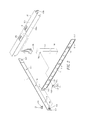
- FIG. 1 is a stereogram showing the combination of a first embodiment of the present invention.
- FIG. 2 is a breakdown stereogram of the first embodiment of the present invention.
- FIG. 3 is a stereogram showing the pivot member of the first embodiment of the present invention.
- FIG. 4 is a longitudinal sectional view of the first embodiment of the present invention.
- FIG. 5 is a transverse sectional view of the first embodiment of the present invention.
- FIG. 6, 7, 8 are schematic diagrams showing rotation angles of the transverse railing according to the first embodiment of the present invention.
- FIG. 9 is a stereogram showing the pivot member of a second embodiment of the present invention.
- FIG. 10 is a sectional view showing the combination of the second embodiment of the present invention.
- FIG. 10 a is a partially enlarged view of FIG. 10 .
- FIG. 11 is a sectional view showing the combination of a third embodiment of the present invention.
- FIG. 12 is a sectional view showing the combination of a fourth embodiment of the present invention.
- the fence structure 1 includes a plurality of vertical pickets 10 having an upper end 100 and a bottom end 101 .
- a sidewall of the vertical picket between the upper end 100 and the bottom end 101 is provided with at least one pivot hole 102 .
- At least one connecting strip 11 is arranged transversely to sidewalls of the plurality of vertical pickets 10 provided with the pivot holes 102 .
- the connecting strip 11 provides a through-hole 110 at the position corresponding to each pivot hole 102 of each single vertical picket 10 .
- One side of the connecting strip 11 leans tightly against the plurality of vertical pickets 10 .
- the bottom end of the connecting strip 11 provides a fastening surface 111 extending outward in a direction away from the vertical picket 10 , and the top surface of the fastening surface 111 is provided with a first oblique sliding surface 1110 .
- either a left or right end of the connecting strip 11 is arranged with a bent strip-coupling element 112 whose center provides a perforation hole 113 , and the other end of the connecting strip 11 (opposite to the strip-coupling element 112 ), at the position corresponding to the perforation hole 113 , is disposed with a protruding clasping element 114 whose end side provides outward hooks 1140 .
- the perforation hole 113 is used for receiving the clasping element 114 .
- the hooks 1140 clasp the edge of the perforation hole 113 to allow those connecting strips 11 to be combined together, as shown in FIG. 5 .
- a plurality of pivot members 12 allows the connecting strip 11 to be pivotally connected with the vertical picket 10 , as shown in FIG. 4 .
- One end of the pivot member 12 provides an inserting end 120 , which is allowed to insert through the through-hole 110 and the pivot hole 102 , as shown in FIG. 4 .
- the other end of the pivot member 12 (opposite to the end of the inserting end 120 ) provides a limiting end 121 whose diameter is larger than the diameter of the through-hole 110 .
- the middle portion of the pivot member 12 provides a middle section 124 which is between the inserting end 120 and the limiting end 121 and whose outer diameter is smaller than the inner diameter of the through-hole 110 and the pivot hole 102 .
- the outer wall of the inserting end 120 adjacent to the middle section 124 is provided with a plurality of outwards-protruding stop elements 1220 arranged annularly to form a stop portion 122 .
- the outer diameter of the stop portion 122 is larger than the inner diameter of the pivot hole 102 .
- the outer wall of the stop portion 122 provides a slanting guiding surface 1221 .
- the slanting guiding surface 1221 has one end wider in diameter than the other end, and the wider end in diameter is near the middle section 124 .
- the inserting end 120 provides an inclined surface 123 which is away from the middle section 124 .
- the outer diameter of the inclined surface 123 gradually increases from the inserting end 120 towards the middle section 124 , as shown in FIG. 3 .
- the middle of the inclined surface 123 is arranged with at least one axially-cut opening 1230 to enable the inserting end 120 to pass through the through-hole 110 and the pivot hole 102 easily.
- At least one transverse railing 13 is provided with a top wall 130 .
- the top wall 130 is arranged with a plurality of spaced picket-holes 131 for receiving the plurality of vertical pickets 10 respectively.
- the diameter of the picket-hole 131 is larger than the diameter of the vertical picket 10 .
- the front and rear ends of the top wall 130 respectively extend downwards to form a front connecting surface 132 a and a rear connecting surface 132 b .
- the bottom end of the front connecting surface 132 a extends towards the fastening surface 111 of the connecting strip 11 to form a locking lip 133 , whose bottom wall provides a second oblique sliding surface 134 , as shown in FIG. 4 .
- each through-hole 110 of the connecting strip 11 is aligned respectively with its relative pivot hole 102 of the vertical picket 10 , and the inserting end 120 of the pivot member 12 is inserted in the through-hole 110 and the pivot hole 102 to the bottom.
- the slanting guiding surface 1221 on the outer wall of the stop portion 122 of the pivot member 12 slides through the edge of the pivot hole 102 to be against the outer wall of the pivot hole 102 in the vertical picket 10 , as shown in FIG. 4 .
- the limiting end 121 at one end of the pivot member 12 is stopped by the connecting strip 11 , and the stop portion 122 of the inserting end 120 at the other end is limited by the vertical picket 10 , so that the pivot member 12 will not slip away from the through-hole 110 and the pivot hole 102 .
- the connecting strip 11 is allowed to be transversely attached to one side of the plurality of vertical pickets 10 , and the connecting strip 11 may also rotate pivotally on the vertical picket 10 via the pivot member 12 .
- the plurality of spaced picket-holes 131 of the transverse railing 13 is aligned with the plurality of vertical pickets 10 respectively.
- the vertical pickets 10 are combined with the transverse railing 13 in a top-down manner.
- the locking lip 133 of the bottom end of the front connecting surface 132 a of the transverse railing 13 is allowed to pass through the surface of the first oblique sliding surface 1110 of the fastening surface 111 of the connecting strip 11 by the second oblique sliding surface 134 to slide to the bottom of the fastening surface 111 of the connecting strip 11 to enable the bottom wall of the top wall 130 of the transverse railing 13 to tightly touch the top end of the connecting strip 11 , and the bottom end of the transverse railing 13 is allowed to clasp the bottom of the fastening surface 111 of the connecting strip 11 .
- the transverse railing 13 and the vertical pickets 10 are secured and combined together by the connecting strip 11 . Moreover, the connecting strip 11 and the pivot member 12 are concealed within the transverse railing 13 . The transverse railing 13 and the connecting strip 11 may simultaneously rotate pivotally within a limited angle.
- the angle of both the transverse railing 13 and the connecting strip 11 of the fence structure 1 is adjustable according to a certain landform.
- the pivot member 12 is the pivot point for the angle adjustment of the transverse railing 13 and the connecting strip 11 .
- the inner walls A and B of the picket-hole 131 of the transverse railing 13 are the largest range/angle that the transverse railing 13 and the connecting strip 11 may pivotally rotate to, as shown in FIG. 5 to FIG. 8 .
- the pivot member 22 includes a limiting end 221 at one end, an inserting end 220 at the opposite end, and a middle section 224 between the inserting end 220 and the limiting end 221 .
- the outer wall of the inserting end 220 adjacent to the middle section 224 is provided with a stop portion 222 including a plurality of outwards-protruding stop elements 2220 arranged annularly.
- the outer diameter of the stop portion 222 is larger than the inner diameter of the pivot hole 102 .
- the outer wall of the inserting end 220 provides an outer threaded section 2201 , arranged adjacent to the plurality of outwards-protruding stop elements 2220 . Moreover, the inserting end 220 is also arranged with at least one axially-cut opening 2202 . When the inserting end 220 of the pivot member 22 inserts into the through-hole 110 and the pivot hole 102 , the at least one axially-cut opening 2202 is in a state of being squeezed, and after the inserting end 220 of the pivot member 22 passes through the through-hole 110 and the pivot hole 102 , the at least one axially-cut opening 2202 returns to its original state. The stop portion 222 can prevent the pivot member 22 from sliding out of the pivot hole 102 .
- the transverse railing 33 disclosed in the third embodiment includes a front connecting surface 332 a and a rear connecting surface 332 b .
- the bottom ends of the front connecting surface 332 a and the rear connecting surface 332 b are respectively bent towards the inner side of the transverse railing 33 and extend upwards to form a front locking lip 333 a and a rear locking lip 333 b .
- the bottom end of the front locking lip 333 a has an arc surface 333 c , which may facilitate downward-sliding through the fastening surface 111 to allow the top end of the front locking lip 333 a to support the fastening surface 111 of the connecting strip 11 when being located and secured.
- FIG. 12 there is shown a combination of the transverse railing 33 of the third embodiment and the pivot member 22 of a second embodiment shown in FIG. 9 and FIG. 10 .
- the stop portion 222 of the pivot member 22 is allowed to be against the edge of the pivot hole 102 of the inner side end of the vertical picket 10 to prevent the pivot member 22 from sliding out of the pivot hole 102 , as shown in FIG. 12 .
- the connecting strip and the vertical picket are connected pivotally by the pivot member. Due to the arrangement of the stop portion, the pivot member also provides functions of fixing and slip-preventing. That is, even when an external force of pulling or pushing is exerted on the picket or railing, the pivot member will not slip away, to enable the connecting strip, the transverse railing and the vertical pickets to stay in place.
- the connecting strip, the transverse railing and the vertical pickets may displace or unfasten resulting when being exerted a pulling or pushing force is allowed to be ameliorated.
Landscapes
- Engineering & Computer Science (AREA)
- Architecture (AREA)
- Civil Engineering (AREA)
- Structural Engineering (AREA)
- Bridges Or Land Bridges (AREA)
Abstract
A fence structure includes a plurality of vertical pickets, at least one connecting strip, a plurality of pivot members, and at least one transverse railing. One end of the pivot member is provided with a stop portion whose outer diameter is larger than the inner diameter of the pivot hole of the vertical picket. The stop portion may limit the pivot member and prevent the pivot member from slipping axially after passing through the connecting strip and the vertical picket. By the aforesaid arrangement, the pivot member not only allows the angle of the transverse railing and the connecting strip to be adjustable according to needs, but also prevents the connecting strip and the vertical pickets from slipping or disconnecting resulting when being exerted by a pulling or pushing force.
Description
1. Field of the Invention
The present invention relates to a fence structure that may reinforce the combination strength of the fence assemblies to keep steady even under being exerted a pulling or pushing force, and allows the angle of the transverse railing and the vertical picket to be adjustable.
2. Description of the Prior Art
As disclosed in U.S. Pat. No. 7,384,025, the prior art fence assembly provides a screw hiding device for combining lateral tubes with upright tubes. The screw hiding device includes a position strip arranged inside the lateral tube. By such an arrangement, the screws and the position strips are allowed to be hidden to beautify the appearance of the fence structure.
An alternative prior art fence assembly disclosed in U.S. Pat. No. 8,413,965 comprises a plurality of vertical pickets which have at least one pivot hole formed therein, a plurality of rails which extend transversely to the vertical pickets and whose top wall provides a plurality of picket openings corresponding to the plurality of vertical pickets to receive the plurality of vertical pickets, and one or more boss strips which are arranged transversely to the side of the vertical picket providing the pivot hole. The boss strip includes a protruding structure corresponding to the pivot hole, and the protruding structure is received inside the pivot hole to allow the boss strip and the vertical picket to rotate pivotally according to needs. The boss strip is arranged between the rail and the vertical picket to hold the rail to avoid sliding down, as shown in FIG. 4 of U.S. Pat. No. 8,413,965. The outer wall of the protruding structure of the boss strip disclosed in U.S. Pat. No. 8,413,965 is a conical surface, such that the rail and the boss strip can only rotate pivotally when the protruding structure is inserted inside the pivot hole. However, the boss strip can not prevent axially-slipping. Hence, the protruding structure whose outer wall is a conical surface will slip easily out of the pivot hole to cause the transverse rail to displace or unfasten when the fence rail or the vertical picket is pushed or pulled by exterior forces. Therefore, the aforesaid structure needs to be improved.
It is against the background and the drawbacks associated therewith that the present invention has been developed.
A primary object objective of the present invention is to provide a fence structure that may reinforce the combination strength of the fence assemblies to keep steady even when being exerted by a pulling or pushing force, and allows the angle of the transverse railing and the vertical picket to be adjustable.
In order to achieve the aforesaid objective, the fence structure disclosed in the present invention comprises a plurality of vertical pickets, at least one connecting strip, a plurality of pivot members, and at least one transverse railing. One end of the pivot member is provided with a stop portion whose outer diameter is larger than the inner diameter of the pivot hole of the vertical picket. The stop portion may limit the pivot member and prevent the pivot member from slipping axially after passing through the connecting strip and the vertical picket. By the aforesaid arrangement, the pivot member not only allows the angle of the transverse railing and the connecting strip to be adjustable according to needs, but also prevents the connecting strip and the vertical pickets from slipping or disconnecting resulting when being exerted by a pulling or pushing force.
In order that the present invention may be more fully understood, preferred embodiments thereof will now be described with reference to the accompanying drawings, in which:
The means for achieving the aforesaid objective and the functions of the present invention will become apparent from the following description, taken in connection with the accompanying drawings, wherein preferred embodiments of the present invention are disclosed.
Referring to FIG. 1 to FIG. 5 , there is shown a fence structure 1 in accordance with a first embodiment of the present invention. The fence structure 1 includes a plurality of vertical pickets 10 having an upper end 100 and a bottom end 101. A sidewall of the vertical picket between the upper end 100 and the bottom end 101 is provided with at least one pivot hole 102.
Referring to FIG. 2 , at least one connecting strip 11 is arranged transversely to sidewalls of the plurality of vertical pickets 10 provided with the pivot holes 102. The connecting strip 11 provides a through-hole 110 at the position corresponding to each pivot hole 102 of each single vertical picket 10. One side of the connecting strip 11 leans tightly against the plurality of vertical pickets 10. As shown in FIG. 4 , the bottom end of the connecting strip 11 provides a fastening surface 111 extending outward in a direction away from the vertical picket 10, and the top surface of the fastening surface 111 is provided with a first oblique sliding surface 1110. In order to enable one connecting strip 11 to connect with another connecting strip 11, either a left or right end of the connecting strip 11 is arranged with a bent strip-coupling element 112 whose center provides a perforation hole 113, and the other end of the connecting strip 11 (opposite to the strip-coupling element 112), at the position corresponding to the perforation hole 113, is disposed with a protruding clasping element 114 whose end side provides outward hooks 1140. The perforation hole 113 is used for receiving the clasping element 114. After the clasping element 114 of one connecting strip 11 inserts into the perforation hole 113 of another connecting strip 11, the hooks 1140 clasp the edge of the perforation hole 113 to allow those connecting strips 11 to be combined together, as shown in FIG. 5 .
A plurality of pivot members 12, as shown in FIG. 3 , allows the connecting strip 11 to be pivotally connected with the vertical picket 10, as shown in FIG. 4 . One end of the pivot member 12 provides an inserting end 120, which is allowed to insert through the through-hole 110 and the pivot hole 102, as shown in FIG. 4 . The other end of the pivot member 12 (opposite to the end of the inserting end 120) provides a limiting end 121 whose diameter is larger than the diameter of the through-hole 110. The middle portion of the pivot member 12 provides a middle section 124 which is between the inserting end 120 and the limiting end 121 and whose outer diameter is smaller than the inner diameter of the through-hole 110 and the pivot hole 102. The outer wall of the inserting end 120 adjacent to the middle section 124 is provided with a plurality of outwards-protruding stop elements 1220 arranged annularly to form a stop portion 122. The outer diameter of the stop portion 122 is larger than the inner diameter of the pivot hole 102. The outer wall of the stop portion 122 provides a slanting guiding surface 1221. The slanting guiding surface 1221 has one end wider in diameter than the other end, and the wider end in diameter is near the middle section 124. The inserting end 120 provides an inclined surface 123 which is away from the middle section 124. The outer diameter of the inclined surface 123 gradually increases from the inserting end 120 towards the middle section 124, as shown in FIG. 3 . The middle of the inclined surface 123 is arranged with at least one axially-cut opening 1230 to enable the inserting end 120 to pass through the through-hole 110 and the pivot hole 102 easily.
At least one transverse railing 13, as shown in FIG. 2 , is provided with a top wall 130. The top wall 130 is arranged with a plurality of spaced picket-holes 131 for receiving the plurality of vertical pickets 10 respectively. The diameter of the picket-hole 131 is larger than the diameter of the vertical picket 10. The front and rear ends of the top wall 130 respectively extend downwards to form a front connecting surface 132 a and a rear connecting surface 132 b. The bottom end of the front connecting surface 132 a extends towards the fastening surface 111 of the connecting strip 11 to form a locking lip 133, whose bottom wall provides a second oblique sliding surface 134, as shown in FIG. 4 .
Referring to FIG. 2 , FIG. 4 and FIG. 5 , when assembling, each through-hole 110 of the connecting strip 11 is aligned respectively with its relative pivot hole 102 of the vertical picket 10, and the inserting end 120 of the pivot member 12 is inserted in the through-hole 110 and the pivot hole 102 to the bottom. The slanting guiding surface 1221 on the outer wall of the stop portion 122 of the pivot member 12 slides through the edge of the pivot hole 102 to be against the outer wall of the pivot hole 102 in the vertical picket 10, as shown in FIG. 4 . The limiting end 121 at one end of the pivot member 12 is stopped by the connecting strip 11, and the stop portion 122 of the inserting end 120 at the other end is limited by the vertical picket 10, so that the pivot member 12 will not slip away from the through-hole 110 and the pivot hole 102. By the aforesaid arrangement, the connecting strip 11 is allowed to be transversely attached to one side of the plurality of vertical pickets 10, and the connecting strip 11 may also rotate pivotally on the vertical picket 10 via the pivot member 12. Next, the plurality of spaced picket-holes 131 of the transverse railing 13 is aligned with the plurality of vertical pickets 10 respectively. The vertical pickets 10 are combined with the transverse railing 13 in a top-down manner. The locking lip 133 of the bottom end of the front connecting surface 132 a of the transverse railing 13 is allowed to pass through the surface of the first oblique sliding surface 1110 of the fastening surface 111 of the connecting strip 11 by the second oblique sliding surface 134 to slide to the bottom of the fastening surface 111 of the connecting strip 11 to enable the bottom wall of the top wall 130 of the transverse railing 13 to tightly touch the top end of the connecting strip 11, and the bottom end of the transverse railing 13 is allowed to clasp the bottom of the fastening surface 111 of the connecting strip 11. The transverse railing 13 and the vertical pickets 10 are secured and combined together by the connecting strip 11. Moreover, the connecting strip 11 and the pivot member 12 are concealed within the transverse railing 13. The transverse railing 13 and the connecting strip 11 may simultaneously rotate pivotally within a limited angle.
Referring to FIG. 5 to FIG. 7 , the angle of both the transverse railing 13 and the connecting strip 11 of the fence structure 1 is adjustable according to a certain landform. The pivot member 12 is the pivot point for the angle adjustment of the transverse railing 13 and the connecting strip 11. The inner walls A and B of the picket-hole 131 of the transverse railing 13 are the largest range/angle that the transverse railing 13 and the connecting strip 11 may pivotally rotate to, as shown in FIG. 5 to FIG. 8 .
Referring to FIG. 9 and FIG. 10 , there is shown a pivot member 22 in accordance with a second embodiment of the present invention. The pivot member 22 includes a limiting end 221 at one end, an inserting end 220 at the opposite end, and a middle section 224 between the inserting end 220 and the limiting end 221. The outer wall of the inserting end 220 adjacent to the middle section 224 is provided with a stop portion 222 including a plurality of outwards-protruding stop elements 2220 arranged annularly. The outer diameter of the stop portion 222 is larger than the inner diameter of the pivot hole 102. The outer wall of the inserting end 220 provides an outer threaded section 2201, arranged adjacent to the plurality of outwards-protruding stop elements 2220. Moreover, the inserting end 220 is also arranged with at least one axially-cut opening 2202. When the inserting end 220 of the pivot member 22 inserts into the through-hole 110 and the pivot hole 102, the at least one axially-cut opening 2202 is in a state of being squeezed, and after the inserting end 220 of the pivot member 22 passes through the through-hole 110 and the pivot hole 102, the at least one axially-cut opening 2202 returns to its original state. The stop portion 222 can prevent the pivot member 22 from sliding out of the pivot hole 102.
Referring to FIG. 11 , the difference between a first embodiment and a third embodiment of the present invention is described as follows: the transverse railing 33 disclosed in the third embodiment includes a front connecting surface 332 a and a rear connecting surface 332 b. The bottom ends of the front connecting surface 332 a and the rear connecting surface 332 b are respectively bent towards the inner side of the transverse railing 33 and extend upwards to form a front locking lip 333 a and a rear locking lip 333 b. The bottom end of the front locking lip 333 a has an arc surface 333 c, which may facilitate downward-sliding through the fastening surface 111 to allow the top end of the front locking lip 333 a to support the fastening surface 111 of the connecting strip 11 when being located and secured. Referring to FIG. 12 , there is shown a combination of the transverse railing 33 of the third embodiment and the pivot member 22 of a second embodiment shown in FIG. 9 and FIG. 10 . The stop portion 222 of the pivot member 22 is allowed to be against the edge of the pivot hole 102 of the inner side end of the vertical picket 10 to prevent the pivot member 22 from sliding out of the pivot hole 102, as shown in FIG. 12 .
According to the aforesaid, the connecting strip and the vertical picket are connected pivotally by the pivot member. Due to the arrangement of the stop portion, the pivot member also provides functions of fixing and slip-preventing. That is, even when an external force of pulling or pushing is exerted on the picket or railing, the pivot member will not slip away, to enable the connecting strip, the transverse railing and the vertical pickets to stay in place. Thus, the deficiency occurring in the prior art that the connecting strip, the transverse railing and the vertical pickets may displace or unfasten resulting when being exerted a pulling or pushing force is allowed to be ameliorated.
It will be appreciated by those skilled in the art that variations and modifications to the invention described herein will be apparent without departing from the spirit and scope thereof. The variations and modifications as would be apparent to persons skilled in the art are deemed to fall within the broad scope and ambit of the invention as herein set forth.
Claims (6)
1. A fence structure comprising:
a vertical picket having an upper end and a bottom end, wherein a sidewall of the vertical picket between the upper end and the bottom end is provided with a pivot hole;
a connecting strip provided with a through-hole corresponding to the pivot hole and is arranged transversely to the sidewall of the vertical picket disposed with the pivot hole, wherein one end of the connecting strip is arranged with a bent strip-coupling element whose center provides a perforation hole, and another end of the connecting strip is disposed with a protruding clasping element which corresponds to the perforation hole and whose side provides outward hooks;
a pivot member inserted in the through-hole and the pivot hole to pivotally connect the connecting strip with the vertical picket, wherein the pivot member provides an inserting end at one end, a limiting end at the opposite end, and a middle section between the inserting end and the limiting end, wherein the limiting end is larger than the through-hole in diameter, the middle section in a state of being inserted within the through-hole and the pivot hole has a smaller diameter than the through-hole and the pivot hole, and the inserting end is inside the vertical picket after passing through the pivot hole; wherein an outer wall of the inserting end is provided with an outward-protruding stop portion whose outer diameter is larger than the inner diameter of the pivot hole, and the outer wall provides a slanting guiding surface having one end with a wider diameter than an opposite end, wherein the one end of the slanting guiding surface is near the middle section; and
a transverse railing arranged transversely on the vertical picket to allow the connecting strip to be hid inside and is provided with a top wall having a picket-hole receiving the vertical picket, wherein the top wall provides a front end and a rear end respectively extending downwards to form a front connecting surface and a rear connecting surface, and wherein a bottom end of the front connecting surface tightly touches a bottom end of the connecting strip and a bottom wall of the top wall tightly touches a top end of the connecting strip.
2. The fence structure as claimed in claim 1 , wherein the bottom end of the connecting strip extends outward in a direction away from the vertical picket to form a fastening surface whose top surface is provided with a first oblique sliding surface, and wherein the bottom end of the front connecting surface extends towards the fastening surface to form a locking lip whose bottom wall provides a second oblique sliding surface.
3. The fence structure as claimed in claim 1 , wherein the bottom end of the connecting strip extends outward in a direction away from the vertical picket to form a fastening surface whose top surface is provided with a first oblique sliding surface, and wherein the bottom end of the front connecting surface of the transverse railing is bent towards an inner side of the transverse railing and extend upwards to form a front locking lip whose bottom end provides an arc surface which allows the transverse railing to downwards slide through the fastening surface to be combined with the connecting strip.
4. The fence structure as claimed in claim 1 , wherein the outwardly protruding stop portion of the pivot member includes a plurality of stop elements arranged annularly.
5. The fence structure as claimed in claim 4 , wherein the inserting end of the pivot member provides an inclined surface away from the middle section, wherein the inclined surface has an outer diameter that gradually increases from the inserting end towards the middle section, and the middle of the inclined surface is arranged with at least one axially-cut opening to enable the inserting end to pass through the through-hole and the pivot hole easily.
6. The fence structure as claimed in claim 5 , wherein the outer wall of the inserting end of the pivot member provides an outer threaded section arranged adjacent to the plurality of stop elements.
Priority Applications (1)
| Application Number | Priority Date | Filing Date | Title |
|---|---|---|---|
| US14/825,218 US9404283B1 (en) | 2015-08-13 | 2015-08-13 | Fence structure |
Applications Claiming Priority (1)
| Application Number | Priority Date | Filing Date | Title |
|---|---|---|---|
| US14/825,218 US9404283B1 (en) | 2015-08-13 | 2015-08-13 | Fence structure |
Publications (1)
| Publication Number | Publication Date |
|---|---|
| US9404283B1 true US9404283B1 (en) | 2016-08-02 |
Family
ID=56507215
Family Applications (1)
| Application Number | Title | Priority Date | Filing Date |
|---|---|---|---|
| US14/825,218 Active US9404283B1 (en) | 2015-08-13 | 2015-08-13 | Fence structure |
Country Status (1)
| Country | Link |
|---|---|
| US (1) | US9404283B1 (en) |
Cited By (8)
| Publication number | Priority date | Publication date | Assignee | Title |
|---|---|---|---|---|
| US20170044793A1 (en) * | 2015-08-10 | 2017-02-16 | Porcelen Limited Connecticut LLC | Aluminum fence design |
| US10648194B2 (en) | 2017-11-10 | 2020-05-12 | Chong-Yi Lo | Fence structure |
| US11035147B2 (en) | 2018-01-08 | 2021-06-15 | Fortress Iron, Lp | Raking barrier panel |
| US11261616B2 (en) * | 2017-06-28 | 2022-03-01 | Khalid Abdus-Samad | Modular fence system |
| US20230123821A1 (en) * | 2020-02-20 | 2023-04-20 | Guardiar Europe Bvba | Fence |
| CN116397959A (en) * | 2023-05-09 | 2023-07-07 | 四川商鼎建设有限公司 | Slope protection system for water conservancy projects |
| US12018506B1 (en) * | 2023-12-05 | 2024-06-25 | Eric Chen Zer Lo | Hidden interconnection arrangement of fence or railing and assembling method thereof |
| US12060727B2 (en) | 2020-09-14 | 2024-08-13 | Paul Thrush | Rackable panel assembly and methods of assembly thereof |
Citations (8)
| Publication number | Priority date | Publication date | Assignee | Title |
|---|---|---|---|---|
| US4821481A (en) * | 1988-03-30 | 1989-04-18 | Woodman Richard C | Lattice and method of making same |
| US6375166B1 (en) * | 2000-03-24 | 2002-04-23 | Delair Group, Inc. | Fence which eliminates the need for conventional fasteners |
| US7152849B2 (en) * | 2003-11-12 | 2006-12-26 | Digger Specialties, Inc. | Fastener |
| US7384025B2 (en) | 2005-10-18 | 2008-06-10 | Chong-Yi Lo | Screw hiding device for combining lateral tubes with upright tubes |
| US20100200827A1 (en) * | 2009-02-09 | 2010-08-12 | Gordon Duffy | Fence/rail assembly with concealed sliding, pivotal connection, and manufacturing method therefor |
| US20110042637A1 (en) * | 2009-08-21 | 2011-02-24 | Keith Howard | Partially pre-assembled fence assembly and mutli-element rail |
| US20110233499A1 (en) * | 2010-03-23 | 2011-09-29 | Stinson William H | Fence Assembly |
| US9027909B1 (en) * | 2013-05-24 | 2015-05-12 | Origin Point Brands, Llc | Rackable screwless fencing system |
-
2015
- 2015-08-13 US US14/825,218 patent/US9404283B1/en active Active
Patent Citations (13)
| Publication number | Priority date | Publication date | Assignee | Title |
|---|---|---|---|---|
| US4821481A (en) * | 1988-03-30 | 1989-04-18 | Woodman Richard C | Lattice and method of making same |
| US6375166B1 (en) * | 2000-03-24 | 2002-04-23 | Delair Group, Inc. | Fence which eliminates the need for conventional fasteners |
| US7152849B2 (en) * | 2003-11-12 | 2006-12-26 | Digger Specialties, Inc. | Fastener |
| US7384025B2 (en) | 2005-10-18 | 2008-06-10 | Chong-Yi Lo | Screw hiding device for combining lateral tubes with upright tubes |
| US8413332B2 (en) * | 2009-02-09 | 2013-04-09 | Barrette Outdoor Living, Inc. | Fence/rail assembly with concealed sliding, pivotal connection, and manufacturing method therefor |
| US20130026433A1 (en) * | 2009-02-09 | 2013-01-31 | Gordon Duffy | Fence/rail assembly with concealed sliding, pivotal connection, and manufacturing method therefor |
| US20130032772A1 (en) * | 2009-02-09 | 2013-02-07 | Gordon Duffy | Fence/rail assembly with concealed sliding, pivotal connection, and manufacturing method therefor |
| US20100200827A1 (en) * | 2009-02-09 | 2010-08-12 | Gordon Duffy | Fence/rail assembly with concealed sliding, pivotal connection, and manufacturing method therefor |
| US8413965B2 (en) | 2009-02-09 | 2013-04-09 | Barrette Outdoor Living, Inc. | Fence/rail assembly with concealed sliding, pivotal connection, and manufacturing method therefor |
| US9151075B2 (en) * | 2009-02-09 | 2015-10-06 | Barrette Outdoor Living, Inc. | Fence/rail assembly with concealed sliding, pivotal connection, and manufacturing method therefor |
| US20110042637A1 (en) * | 2009-08-21 | 2011-02-24 | Keith Howard | Partially pre-assembled fence assembly and mutli-element rail |
| US20110233499A1 (en) * | 2010-03-23 | 2011-09-29 | Stinson William H | Fence Assembly |
| US9027909B1 (en) * | 2013-05-24 | 2015-05-12 | Origin Point Brands, Llc | Rackable screwless fencing system |
Cited By (14)
| Publication number | Priority date | Publication date | Assignee | Title |
|---|---|---|---|---|
| US20170044793A1 (en) * | 2015-08-10 | 2017-02-16 | Porcelen Limited Connecticut LLC | Aluminum fence design |
| US9695612B2 (en) * | 2015-08-10 | 2017-07-04 | Porcelen Limited Connecticut LLC | Aluminum fence design |
| US11261616B2 (en) * | 2017-06-28 | 2022-03-01 | Khalid Abdus-Samad | Modular fence system |
| US10648194B2 (en) | 2017-11-10 | 2020-05-12 | Chong-Yi Lo | Fence structure |
| US11035147B2 (en) | 2018-01-08 | 2021-06-15 | Fortress Iron, Lp | Raking barrier panel |
| US12421755B2 (en) * | 2018-01-08 | 2025-09-23 | Fortress Iron, Lp | Raking barrier panel |
| US11988011B2 (en) | 2018-01-08 | 2024-05-21 | Fortress Iron, Lp | Raking barrier panel |
| US20240301717A1 (en) * | 2018-01-08 | 2024-09-12 | Fortress Iron, Lp | Raking barrier panel |
| US20230123821A1 (en) * | 2020-02-20 | 2023-04-20 | Guardiar Europe Bvba | Fence |
| US12060727B2 (en) | 2020-09-14 | 2024-08-13 | Paul Thrush | Rackable panel assembly and methods of assembly thereof |
| CN116397959A (en) * | 2023-05-09 | 2023-07-07 | 四川商鼎建设有限公司 | Slope protection system for water conservancy projects |
| US12018506B1 (en) * | 2023-12-05 | 2024-06-25 | Eric Chen Zer Lo | Hidden interconnection arrangement of fence or railing and assembling method thereof |
| US12320140B1 (en) * | 2023-12-05 | 2025-06-03 | Eric Chen Zer Lo | Hidden interconnection arrangement of fence or railing and assembling method thereof |
| US20250179831A1 (en) * | 2023-12-05 | 2025-06-05 | Eric Chen Zer Lo | Hidden Interconnection Arrangement of Fence or Railing and Assembling Method Thereof |
Similar Documents
| Publication | Publication Date | Title |
|---|---|---|
| US9404283B1 (en) | Fence structure | |
| US7757997B2 (en) | Clip for fastening an article to a panel having a self-expanding clip head | |
| USD820192S1 (en) | Rooftop tent | |
| US20170260809A1 (en) | Stretchable ladder | |
| US9380868B1 (en) | Structure of coupling sleeve of storage shelf | |
| US9605441B2 (en) | Tent frame top connecting structure | |
| US20110302874A1 (en) | Post wrap device | |
| USD936265S1 (en) | Umbrella light | |
| US20160160900A1 (en) | Baluster connector | |
| US8919826B2 (en) | Screen frame grasping and removal system | |
| US8083345B2 (en) | Glasses hinge structure | |
| US20190110593A1 (en) | Suspension System | |
| CN109594501A (en) | Fence sytsem and method | |
| CN110285121A (en) | Furniture system | |
| US20180258656A1 (en) | Railing system | |
| US20160251897A1 (en) | Expandable Fence Gate Frame Assembly | |
| US20210293086A1 (en) | Window shade | |
| AU2008338247B2 (en) | Interlocking assembly system and method | |
| US20070240748A1 (en) | Canopy | |
| IT201600084644A1 (en) | Concealed junction system for furniture or similar panels | |
| US9788654B1 (en) | Drawer slide rail | |
| US8925148B2 (en) | Rod brackets and related systems and methods | |
| JP7340651B2 (en) | Connecting parts for stairs | |
| KR101555508B1 (en) | Ladder structure for vehicle roof tent | |
| US20160376833A1 (en) | Louver Assembly |
Legal Events
| Date | Code | Title | Description |
|---|---|---|---|
| STCF | Information on status: patent grant |
Free format text: PATENTED CASE |
|
| MAFP | Maintenance fee payment |
Free format text: PAYMENT OF MAINTENANCE FEE, 4TH YR, SMALL ENTITY (ORIGINAL EVENT CODE: M2551); ENTITY STATUS OF PATENT OWNER: SMALL ENTITY Year of fee payment: 4 |
|
| MAFP | Maintenance fee payment |
Free format text: PAYMENT OF MAINTENANCE FEE, 8TH YR, SMALL ENTITY (ORIGINAL EVENT CODE: M2552); ENTITY STATUS OF PATENT OWNER: SMALL ENTITY Year of fee payment: 8 |