US9402999B2 - Transdermal medical patch - Google Patents
Transdermal medical patch Download PDFInfo
- Publication number
- US9402999B2 US9402999B2 US13/464,634 US201213464634A US9402999B2 US 9402999 B2 US9402999 B2 US 9402999B2 US 201213464634 A US201213464634 A US 201213464634A US 9402999 B2 US9402999 B2 US 9402999B2
- Authority
- US
- United States
- Prior art keywords
- patch
- medical patch
- outer perimeter
- cushioning layer
- medical
- Prior art date
- Legal status (The legal status is an assumption and is not a legal conclusion. Google has not performed a legal analysis and makes no representation as to the accuracy of the status listed.)
- Expired - Fee Related, expires
Links
- 229920000642 polymer Polymers 0.000 claims description 19
- 230000007704 transition Effects 0.000 claims description 12
- 239000000463 material Substances 0.000 claims description 11
- 230000004888 barrier function Effects 0.000 claims description 2
- 238000007789 sealing Methods 0.000 claims description 2
- XLYOFNOQVPJJNP-UHFFFAOYSA-N water Substances O XLYOFNOQVPJJNP-UHFFFAOYSA-N 0.000 claims description 2
- 230000002708 enhancing effect Effects 0.000 claims 1
- 239000006261 foam material Substances 0.000 claims 1
- 230000001070 adhesive effect Effects 0.000 abstract description 54
- 239000000853 adhesive Substances 0.000 abstract description 53
- 230000000638 stimulation Effects 0.000 abstract description 18
- 210000001032 spinal nerve Anatomy 0.000 abstract description 10
- 206010040880 Skin irritation Diseases 0.000 abstract description 7
- 230000036556 skin irritation Effects 0.000 abstract description 7
- 231100000475 skin irritation Toxicity 0.000 abstract description 7
- 239000006260 foam Substances 0.000 abstract description 3
- 239000010410 layer Substances 0.000 description 44
- 210000005036 nerve Anatomy 0.000 description 28
- 239000000017 hydrogel Substances 0.000 description 25
- 238000002560 therapeutic procedure Methods 0.000 description 10
- 239000011248 coating agent Substances 0.000 description 9
- 238000000576 coating method Methods 0.000 description 9
- 230000001681 protective effect Effects 0.000 description 9
- 238000000034 method Methods 0.000 description 8
- 239000002537 cosmetic Substances 0.000 description 6
- 230000007383 nerve stimulation Effects 0.000 description 6
- 239000002831 pharmacologic agent Substances 0.000 description 6
- 238000003825 pressing Methods 0.000 description 6
- 239000011800 void material Substances 0.000 description 6
- 230000005684 electric field Effects 0.000 description 5
- 229940079593 drug Drugs 0.000 description 4
- 239000003814 drug Substances 0.000 description 4
- 238000001125 extrusion Methods 0.000 description 4
- -1 pain medication Substances 0.000 description 4
- 238000004891 communication Methods 0.000 description 3
- 238000013461 design Methods 0.000 description 3
- 229940088597 hormone Drugs 0.000 description 3
- 239000005556 hormone Substances 0.000 description 3
- 230000003287 optical effect Effects 0.000 description 3
- 229940124583 pain medication Drugs 0.000 description 3
- 206010046543 Urinary incontinence Diseases 0.000 description 2
- 238000013459 approach Methods 0.000 description 2
- 210000000988 bone and bone Anatomy 0.000 description 2
- 230000001747 exhibiting effect Effects 0.000 description 2
- 230000006870 function Effects 0.000 description 2
- 238000004806 packaging method and process Methods 0.000 description 2
- 230000008569 process Effects 0.000 description 2
- 238000003860 storage Methods 0.000 description 2
- 238000006467 substitution reaction Methods 0.000 description 2
- 206010013710 Drug interaction Diseases 0.000 description 1
- JOYRKODLDBILNP-UHFFFAOYSA-N Ethyl urethane Chemical compound CCOC(N)=O JOYRKODLDBILNP-UHFFFAOYSA-N 0.000 description 1
- 208000034347 Faecal incontinence Diseases 0.000 description 1
- 206010033799 Paralysis Diseases 0.000 description 1
- 229920005830 Polyurethane Foam Polymers 0.000 description 1
- 239000004775 Tyvek Substances 0.000 description 1
- 229920000690 Tyvek Polymers 0.000 description 1
- NIXOWILDQLNWCW-UHFFFAOYSA-N acrylic acid group Chemical group C(C=C)(=O)O NIXOWILDQLNWCW-UHFFFAOYSA-N 0.000 description 1
- 239000012790 adhesive layer Substances 0.000 description 1
- 230000002411 adverse Effects 0.000 description 1
- 230000002009 allergenic effect Effects 0.000 description 1
- 230000008901 benefit Effects 0.000 description 1
- 230000002457 bidirectional effect Effects 0.000 description 1
- 210000004204 blood vessel Anatomy 0.000 description 1
- 210000003169 central nervous system Anatomy 0.000 description 1
- 230000000295 complement effect Effects 0.000 description 1
- 230000006378 damage Effects 0.000 description 1
- 238000000586 desensitisation Methods 0.000 description 1
- 230000009977 dual effect Effects 0.000 description 1
- 230000000694 effects Effects 0.000 description 1
- 239000005038 ethylene vinyl acetate Substances 0.000 description 1
- 230000007849 functional defect Effects 0.000 description 1
- 239000000499 gel Substances 0.000 description 1
- 208000015181 infectious disease Diseases 0.000 description 1
- 230000007794 irritation Effects 0.000 description 1
- 238000002386 leaching Methods 0.000 description 1
- 230000003902 lesion Effects 0.000 description 1
- 238000004519 manufacturing process Methods 0.000 description 1
- 238000013160 medical therapy Methods 0.000 description 1
- 230000027939 micturition Effects 0.000 description 1
- 230000004048 modification Effects 0.000 description 1
- 238000012986 modification Methods 0.000 description 1
- 210000003205 muscle Anatomy 0.000 description 1
- 231100000252 nontoxic Toxicity 0.000 description 1
- 230000003000 nontoxic effect Effects 0.000 description 1
- 231100000862 numbness Toxicity 0.000 description 1
- 210000000056 organ Anatomy 0.000 description 1
- 239000005022 packaging material Substances 0.000 description 1
- 210000001428 peripheral nervous system Anatomy 0.000 description 1
- 230000000144 pharmacologic effect Effects 0.000 description 1
- 239000004033 plastic Substances 0.000 description 1
- 229920003023 plastic Polymers 0.000 description 1
- 229920006264 polyurethane film Polymers 0.000 description 1
- 239000011496 polyurethane foam Substances 0.000 description 1
- 238000009877 rendering Methods 0.000 description 1
- 230000000284 resting effect Effects 0.000 description 1
- 230000001953 sensory effect Effects 0.000 description 1
- 230000037380 skin damage Effects 0.000 description 1
- 239000007787 solid Substances 0.000 description 1
- 230000007480 spreading Effects 0.000 description 1
- 238000003892 spreading Methods 0.000 description 1
- 230000004936 stimulating effect Effects 0.000 description 1
- 239000000758 substrate Substances 0.000 description 1
- 238000001356 surgical procedure Methods 0.000 description 1
- 230000001225 therapeutic effect Effects 0.000 description 1
- 210000001519 tissue Anatomy 0.000 description 1
- 230000002485 urinary effect Effects 0.000 description 1
- 230000000007 visual effect Effects 0.000 description 1
Images


Classifications
-
- A—HUMAN NECESSITIES
- A61—MEDICAL OR VETERINARY SCIENCE; HYGIENE
- A61N—ELECTROTHERAPY; MAGNETOTHERAPY; RADIATION THERAPY; ULTRASOUND THERAPY
- A61N1/00—Electrotherapy; Circuits therefor
- A61N1/18—Applying electric currents by contact electrodes
- A61N1/20—Applying electric currents by contact electrodes continuous direct currents
- A61N1/30—Apparatus for iontophoresis, i.e. transfer of media in ionic state by an electromotoric force into the body, or cataphoresis
- A61N1/303—Constructional details
-
- A—HUMAN NECESSITIES
- A61—MEDICAL OR VETERINARY SCIENCE; HYGIENE
- A61N—ELECTROTHERAPY; MAGNETOTHERAPY; RADIATION THERAPY; ULTRASOUND THERAPY
- A61N1/00—Electrotherapy; Circuits therefor
- A61N1/02—Details
- A61N1/04—Electrodes
- A61N1/0404—Electrodes for external use
- A61N1/0408—Use-related aspects
- A61N1/0428—Specially adapted for iontophoresis, e.g. AC, DC or including drug reservoirs
-
- A—HUMAN NECESSITIES
- A61—MEDICAL OR VETERINARY SCIENCE; HYGIENE
- A61N—ELECTROTHERAPY; MAGNETOTHERAPY; RADIATION THERAPY; ULTRASOUND THERAPY
- A61N1/00—Electrotherapy; Circuits therefor
- A61N1/02—Details
- A61N1/04—Electrodes
- A61N1/0404—Electrodes for external use
- A61N1/0408—Use-related aspects
- A61N1/0456—Specially adapted for transcutaneous electrical nerve stimulation [TENS]
-
- A—HUMAN NECESSITIES
- A61—MEDICAL OR VETERINARY SCIENCE; HYGIENE
- A61N—ELECTROTHERAPY; MAGNETOTHERAPY; RADIATION THERAPY; ULTRASOUND THERAPY
- A61N1/00—Electrotherapy; Circuits therefor
- A61N1/02—Details
- A61N1/04—Electrodes
- A61N1/0404—Electrodes for external use
- A61N1/0472—Structure-related aspects
- A61N1/0492—Patch electrodes
-
- A—HUMAN NECESSITIES
- A61—MEDICAL OR VETERINARY SCIENCE; HYGIENE
- A61N—ELECTROTHERAPY; MAGNETOTHERAPY; RADIATION THERAPY; ULTRASOUND THERAPY
- A61N1/00—Electrotherapy; Circuits therefor
- A61N1/18—Applying electric currents by contact electrodes
- A61N1/32—Applying electric currents by contact electrodes alternating or intermittent currents
- A61N1/36—Applying electric currents by contact electrodes alternating or intermittent currents for stimulation
- A61N1/36014—External stimulators, e.g. with patch electrodes
Definitions
- the present invention is directed to a medical patch and, in particular, an improved transdermal medical patch for providing a treatment therapy such as electrical stimulation and/or delivery of a pharmacological agent such as pain medication, drugs, and hormones.
- a treatment therapy such as electrical stimulation and/or delivery of a pharmacological agent such as pain medication, drugs, and hormones.
- Nerves are part of the peripheral nervous system of a human body. They convey sensory signals back and forth from the skin and body organs to the central nervous system. Nerves may become damaged due to wear and tear, physical injuries, infection, and/or the failure of the blood vessels surrounding the nerves. These functional defects may be accompanied by pain, numbness, weakness and in some cases, paralysis. Other problems resulting from damaged nerves may include urinary and fecal incontinence.
- treating urinary incontinence may involve behavior modification such as urinating more frequently and wearing protective undergarments.
- behavior modification such as urinating more frequently and wearing protective undergarments.
- individuals may not be able to follow the practice of frequent urination or wearing protective undergarments.
- Another approach involves a medical therapy including taking prescribed drugs.
- this methodology may result in adverse side effects or drug interactions that will ultimately require discontinuation.
- Still another technique for treating the above-noted conditions involves stimulation using an electro-medical device that is positioned near a target nerve.
- an electro-medical device is commonly referred to as an Implantable Pulse Generator (IPG), which typically includes one or more electrodes, an electrical pulse generator and a power source (e.g., internal and/or external to the body).
- IPG Implantable Pulse Generator
- the electrical pulse generator generates an electrical signal adapted to stimulate a target nerve.
- the electrodes receive the signal from the generator, they draw energy from the power source and generate an electric field of suitable strength to stimulate the target nerve.
- Implantable Pulse Generators are somewhat effective for stimulating nerves; however, such devices are extremely invasive since they are implanted inside a patient's body during a surgical procedure. Furthermore, IPG's consume a significant amount of power, which may be due to an increase in electrical impedance between the electrodes, or an increase in electrical impedance between the electrodes and the IPG. Increased power consumption may also be caused by a phenomenon referred to as “desensitization of stimulus,” whereby the human body responds to an applied external charge by offering a resistance to the applied external charge. The body resists the applied external charge by increasing the stimulation threshold for a target nerve, thereby rendering the earlier stimulus level ineffective. To overcome this problem, a more powerful charge must be generated, which consumes even more battery power and requires frequent replacement and/or recharging of the batteries.
- the generated electric field spreads widely, undesirably affecting untargeted muscles and nerves along with the target nerve.
- the wide spreading of the electric field significantly reduces the strength of the electrical signal at the target nerve.
- the strength of the electrical signal In order to properly stimulate the target nerve, the strength of the electrical signal must be substantially increased, which requires the device to draw more power from the battery thereby consuming greater energy.
- non-invasive selective nerve stimulation (SNS) medical patches are disclosed in commonly assigned U.S. Patent Publication Nos.: 2005/0277998, filed Jun. 7, 2005 and 2006/0195153, filed Jan. 31, 2006, the disclosures of which are each hereby incorporated by reference in their entirety herein.
- these publications teach a non-invasive, transcutaneous neurostimulation patch that generates and transmits a controlled, amplitude-modulated waveform comprising a carrier signal and a pulse envelope.
- the carrier waveform is designed to be of sufficient frequency to overcome attenuation due to tissue impedances.
- the pulse envelope contains specific pulse width, amplitude and shape information designed to stimulate specific nerves.
- Medical patches are often adhered to a patient's skin with an active or operating portion of the patch directed toward a target location (e.g., one or more targeted nerves) on the patient.
- a target location e.g., one or more targeted nerves
- the medical patch produces electrical signals and/or delivers a pharmacological agent for achieving a therapeutic benefit to a target site of the body.
- a series of medical patches are sequentially in time applied to the patient, whereby a first medical patch applied by a medical professional is removed from a patient's skin and replaced with a second medical patch. After the passage of time, the second medical patch is removed and replaced by a third medical patch, and so on.
- application of the second and subsequent medical patches to the body is often conducted by the patient himself/herself at home. Due to inexperience, replacement medical patches may be improperly aligned over the target site on the patient, e.g. a particular nerve that is the target for nerve stimulation, resulting in less effective treatment therapy.
- transcutaneous medical patches typically include electronic circuitry that may, over time, cause skin irritation, redness or lesions. This is of particular concern when the same medical patch remains adhered at the same location on the body for an extended period of time, for example, several days or more. It would therefore be desirable to reduce the occurrence of skin irritation thereby increasing the duration of time over which the medical patch may remain adhered to the same location on the body.
- the present invention is directed to an improved system and method for self-positioning and aligning medical patches that provide a treatment therapy in the form of electrical signals and/or pharmacological agents such as pain medication, drugs, and hormones.
- the medical patch in accordance with the present invention enables patients, while at home and unassisted, to self-locate and place medical patches over one or more target sites on the patient's body.
- One aspect of the present invention is directed to a medical patch having a multi-piece bottom liner including a central liner sequentially removable independently of two outer perimeter liners.
- the multi-piece liner covering two adhesives of different peel force. Removal of the central liner exposes a first temporary/repositionable adhesive. Once properly positioned, the outer perimeter liners are removed to expose a second stronger adhesive.
- a foam cushioning layer is disposed beneath and extends beyond a footprint of every printed circuit board to prevent skin irritation.
- the medical patch may be designed specifically for stimulation of the sacral (S 3 foramen) spinal nerve without the use of a separate mechanical placement tool or assistance by another.
- the medical patch has electronic circuitry including at least one printed circuit board; and a cushioning layer having a bottom surface, an opposite top surface, a side surface and an outer perimeter.
- the at least one printed circuit board is disposed on the top surface of the cushioning layer.
- the outer perimeter of the cushioning layer extends two dimensionally in all directions beyond a footprint of each of the at least one printed circuit board.
- Yet another aspect of the present invention is directed to a medical patch having an outer perimeter extending between a leading end and a trailing end.
- the medical patch has electronic circuitry including at least one printed circuit board; and a cushioning layer having a bottom surface, an opposite top surface, a side surface and an outer perimeter.
- the at least one printed circuit board is disposed on the top surface of the cushioning layer.
- the outer perimeter of the cushioning layer extends two dimensionally in all directions beyond a footprint of each of the at least one printed circuit board.
- Some of the at least one printed circuit boards have at least one surface mounted electronic component.
- a polymer layer encloses the top surface of each of the at least one printed circuit boards having the at least one surface mounted electronic component.
- the polymer layer is in contact with only a portion of the cushioning layer not covered by the at least one circuit board; the polymer layer being disposed inward from the outer perimeter of the cushioning layer.
- a top coat completely encloses the polymer layer and extends to the outer perimeter of the cushioning layer.
- Still another aspect of the present invention is directed to a medical patch having a top surface, an opposite bottom surface and an outer perimeter extending between a trailing end and an opposite leading end.
- the medical patch includes: a first adhesive centrally disposed inward from the outer perimeter on only a portion of the bottom surface of the medical patch; a second adhesive disposed only proximate its outer perimeter on the bottom surface of the medical patch without overlapping the first adhesive, wherein the second adhesive exhibiting a higher peel force than that of the first adhesive.
- the medical patch also has a multi-piece liner including: a central liner disposed on only a portion of the bottom surface of the patch completely covering the first adhesive, wherein an outer perimeter of the central liner is disposed inward a predetermined distance from the outer perimeter of the patch; a leading end outer perimeter liner covering only a leading portion of the bottom surface of the medical patch proximate the leading end and extending to the outer perimeter of the medical patch; and a trailing end outer perimeter liner covering only a trailing portion of the bottom surface of the medical patch disposed proximate the trailing end and extends to the outer perimeter of the medical patch.
- Each of the outer perimeter liners are laterally folded over onto itself with its outer contour substantially aligned.
- the outer perimeter liners are arranged so that respective folds of each of the outer perimeters abut one another along a fold line interface thereby defining an opening that exposes the first adhesive.
- the central liner overlaps only a portion of each of the outer perimeter liners, while the outer perimeter liners together with the central liner completely cover the bottom surface of the medical patch.
- One other aspect of the present invention is directed to a medical patch having a top surface, an opposite bottom surface and an outer perimeter extending between a trailing end and an opposite leading end.
- the medical patch includes: a first adhesive centrally disposed inward from the outer perimeter on only a portion of the bottom surface of the medical patch; a second adhesive disposed only proximate its outer perimeter on the bottom surface of the medical patch without overlapping the first adhesive, wherein the second adhesive exhibiting a higher peel force than that of the first adhesive.
- the medical patch also has a multi-piece liner including: a central liner disposed on only a portion of the bottom surface of the patch completely covering the first adhesive, wherein an outer perimeter of the central liner is disposed inward a predetermined distance from the outer perimeter of the patch; a leading end outer perimeter liner covering only a leading portion of the bottom surface of the medical patch proximate the leading end and extending to the outer perimeter of the medical patch; and a trailing end outer perimeter liner covering only a trailing portion of the bottom surface of the medical patch disposed proximate the trailing end and extends to the outer perimeter of the medical patch.
- Each of the outer perimeter liners are laterally folded over onto itself with its outer contour substantially aligned.
- the outer perimeter liners are arranged so that respective folds of each of the outer perimeters abut one another along a fold line interface thereby defining an opening that exposes the first adhesive.
- the central liner overlaps only a portion of each of the outer perimeter liners, while the outer perimeter liners together with the central liner completely cover the bottom surface of the medical patch.
- Each of the outer perimeter liners when folded defines two overlapping sections including a contacting section which is in contact with only the second adhesive, and an opposite non-contacting section not in contact with either of the adhesives.
- a leading end outer perimeter pull tab extends from the non-contacting section of the leading end outer perimeter liner beyond the outer perimeter of the medical patch, while a leading end adherence tab extends from the non-contacting section of the leading end outer perimeter liner into the opening.
- a trailing end outer perimeter pull tab extends from the non-contacting section of the trailing end outer perimeter liner beyond the outer perimeter of the medical patch, while a trailing end adherence tab extends from the non-contacting section of the trailing end outer perimeter liner into the opening.
- Another aspect of the present invention is directed to a method for applying to a human body the medical patch as described in the preceding paragraph.
- the central liner is removed thereby exposing the first adhesive, while the outer perimeter liners are maintained in place adhered to the medical patch.
- the medical patch With the first adhesive exposed, the medical patch is positioned on the human body and adhered via the first adhesive.
- a first hand pressing down from the top surface the trailing end of the patch while simultaneously, with a second hand, pulling the leading end outer perimeter liner pull tab to remove the leading end outer perimeter liner and expose the second adhesive underneath.
- the second hand pressing down from the top surface the leading end of the patch while simultaneously, with the first hand, pulling the trailing end outer perimeter liner pull tab attached to remove the trailing end outer perimeter liner and expose the second adhesive underneath.
- Still yet another aspect of the present invention is directed to a self-positioning neurostimulation medical patch for stimulation of a sacral (S 3 foramen) spinal nerve, wherein the medical patch has a top surface, a bottom surface, an outer perimeter, a leading end and an opposite trailing end, the leading and trailing ends defining a central longitudinal axis.
- An electrode generates an electrical signal, wherein the electrode is disposed proximate the leading end of the medical patch.
- the bottom surface of the medical patch is covered by a liner.
- the outer perimeter of the medical patch has a linear section disposed symmetrically on both sides of the central longitudinal axis. These linear sections are oriented at an angle of approximately ⁇ 60 degrees relative to the central longitudinal axis while the electrode is disposed at an intersection of parallel lines approximately 2 cm inward relative to the respective linear sections.
- While yet another aspect of the present invention relates to a method for unassisted self-positioning of the neurostimulation medical patch as described in the preceding paragraph. Initially, a tail bone is located via tactile manipulation. Then, approximately 9 cm upwards along the spine from the tail bone is measured to identify an anatomical reference point. Lastly, the medical patch is positioned so that an end of one of the linear sections closest to the central longitudinal axis substantially coincides with the anatomical reference point and that linear section is substantially aligned with the spine.
- FIG. 1A is a top view of an exemplary neurostimulation medical patch in accordance with the present invention with the top protective covering and multi-piece liner intact;
- FIG. 1B is a bottom view of the neurostimulation medical patch of FIG. 1A ;
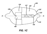
- FIG. 1C is a bottom view of the neurostimulation medical patch of FIG. 1A after the central liner has been removed leaving intact both outer perimeter liners;
- FIG. 1D is a bottom view of the neurostimulation medical patch of FIG. 1A with the central liner and both outer perimeter liners removed;
- FIG. 1E is an exploded view of the neurostimulation medical patch of FIG. 1A ;
- FIG. 1F is a front view of the contacting section of the trailing end outer perimeter liner of FIG. 1C folded onto itself;
- FIG. 1G is a front view of the non-contacting section of the trailing end outer perimeter liner of FIG. 1C folded onto itself;
- FIG. 1H is a front view of the contacting section of the leading end outer perimeter liner of FIG. 1C folded onto itself;
- FIG. 1I is a front view of the non-contacting section of the leading end outer perimeter liner of FIG. 1C folded onto itself;
- FIGS. 1J-1L illustrate sequential steps in removing the leading end outer perimeter liner from the bottom of the medical patch
- FIGS. 1M & 1N illustrate sequential steps in removing the trailing end outer perimeter liner from the bottom of the medical patch
- FIG. 2A is a cross-sectional view of the patch in FIG. 1D along line II-II;
- FIG. 2B is a cross-sectional view of an alternative embodiment of the patch in FIG. 1D along line II-II with a compensated step-down transition of the cosmetic cover and top coat to minimize skin extrusion;
- FIG. 2C is a cross-section view of yet another embodiment of the patch in FIG. 1D along line II-II in which the cosmetic cover has been eliminated and the cushioning layer is configured to minimize skin extrusion;
- FIG. 3 is a bottom view of still another configuration of the patch in accordance with the present invention in which the serpentine path between the electrodes as shown in FIG. 1D is replaced by a relatively thin wire with the cushioning layer removed along the wire between the electrodes;
- FIG. 4 represents the medical patch of FIG. 1A properly positioned over the sacral (S 3 foramen) spinal nerve using the anatomical references without the need for a separate mechanical placement tool;
- FIG. 5 depicts illustrates the angular and translational forgiveness provided by the circular and square shape electrode configuration of the medical patch in accordance with FIG. 1D .
- the present invention is directed to a medical patch to transdermally deliver a treatment therapy to a target site of the body.
- the treatment therapy provided by the medical patch to the target site of the body may include electrical stimulation and/or delivery of a pharmacological agent such as pain medication, drugs or hormones.
- a pharmacological agent such as pain medication, drugs or hormones.
- the medical patch is shown and described as providing neurostimulation to one or more targeted nerves via electrical stimulation.
- the present inventive transdermal medical patch may be adapted to provide treatment therapy to any desired target site of the body (not just one or more nerves) and deliver a pharmacological agent in addition to, or instead of electrical stimulation. Both the type of treatment therapy provided and the target site may be selected, as desired, depending on the medical condition being treated.
- FIG. 1A is a top view of the exemplary medical patch 100 , such as a nerve stimulation patch, with the top protective covering and multi-piece liners intact.
- An exploded view of the medical patch in FIG. 1A is depicted in FIG. 1E .
- Patch 100 has an outer perimeter 103 that extends between a leading end 105 and an opposite trailing end 110 .
- top protective covering 112 During storage and prior to placement on a patient, the medical patch is protected by a removable top protective covering 112 .
- a pull tab 114 may be grasped and pulled upwards to assist in removal of the top protective covering 112 from a raincoat or top coat 190 .
- the top coat 190 provides a water resistant barrier for the electronics of the medical patch enclosed beneath it.
- Top coat 190 preferably a clear polyurethane film coated with an acrylic base biocompatible skin adhesive, completely covers and extends beyond the footprint of the electronic circuitry 165 so that a region of the top coat proximate its outer perimeter is secured to the skin via the biocompatible skin adhesive coating disposed on its bottom surface.
- the thickness of the top coat 190 is preferably less than or equal to approximately 0.001 inch.
- top coat 190 has a relief contour substantially conforming to that of electronic circuitry 165 which includes one or more electrical components powered by a power source 102 , for example, a battery.
- a power source 102 for example, a battery.
- an external power source may power the medical patch remotely such as during RF communication.
- Communication between the medical patch and an external device, for example, a control device or programmer, is provided by transmitter/receiver circuitry 106 (also referred to as optical element or optical eye) included as part of the electronic circuitry in the medical patch.
- the electronic circuitry 165 may be modified, as desired, depending on the treatment therapy provided.
- the electronic circuitry further includes one or more electrodes for providing electrical stimulation to a targeted nerve when adhered to the body.
- Patch 100 in the exemplary configuration depicted throughout the figures, has two electrodes, e.g., a first electrode 155 disposed proximate the leading end 105 (as shown in FIG. 1E ) and a second electrode 160 (as seen in FIG. 1C visible below the respective transparent adhesive gel pads) proximate the trailing end 110 . Any number of one or more electrodes may be employed, as desired, to provide electrical stimulation.
- the medical patch may be designed without any electrodes, instead providing only delivery of a pharmacological agent as the prescribed therapy treatment.
- first electrode 155 is circular in shape
- second electrode 160 is in the shape of a square.
- shape and size of each electrode may be modified, as desired, to produce a desired electric field sufficient in strength and shape to stimulate at least one targeted nerve.
- a polymer 170 such as clear, solid Ethylene Vinyl Acetate (EVA) Surebonder 707 sold by FPC Corporation, Wauconda, Ill.
- Top coat 190 covers polymer 170 .
- the polymer provides enhanced rigidity to the otherwise flimsy patch while hermetically sealing the electronic circuitry from air and moisture. Any biocompatible/non-toxic polymers may be used.
- the polymer is transparent or clear to allow optical bidirectional infrared data communication between the electronic circuitry of the medical patch and an external control device.
- a cosmetic cover layer 180 (as shown in FIG. 2A ), preferably flesh colored, may be disposed between the polymer 170 and top coat 190 so that the medical patch is less conspicuous.
- Electronic circuitry that is rigid and inflexible (e.g., printed circuit boards or any other rigid substrate) when placed in direct contact with the skin may cause irritation.
- a cushioning layer is disposed beneath all printed circuit boards associated with electronic circuitry 165 preventing direct contact with the skin.
- electronic circuitry 165 includes rigid printed circuit boards disposed atop the respective square 160 and circular 155 electrodes.
- Any biocompatible and non-allergenic material that serves as a cushion may be employed as the cushioning layer such as, but not limited to, polyurethane foam preferably having a thickness greater than approximately 0.012 inch, more preferably in the range of approximately 0.014 inch—approximately 0.018 inch, most preferably approximately 0.016 inch.
- cushioning layer material selected includes a relatively high moisture-vapor transition rate (MTVR), preferably greater than approximately 500 gm/m 2 /24 hour, that wicks moisture away from underneath the patch.
- MTVR moisture-vapor transition rate
- the footprint or outer perimeter of cushioning layer 175 is greater than/extends beyond that of each of the printed circuit boards, preferably greater than approximately 0.030 inch, more preferably in a range between approximately 0.050 inch to approximately 0.150 inch, depending on the geometry/layering of patch materials that make up the transition between the patch and the skin.
- the cushioning layer extends beyond the printed circuit boards by approximately 1.5-2 times the thickness of the cushioning layer.
- a preferred cushioning layer thickness is approximately 0.016 inch, so the footprint or outer perimeter of cushioning layer 175 extends beyond that of the printed circuit boards by approximately 0.32 inch.
- a corresponding number of openings similar in size and shape to the respective electrodes are defined in the cushioning layer 175 and substantially aligned therewith.
- These pads serve a dual function to both assist in the delivery of electrical signals while simultaneously providing a temporary/repositionable adhesive. Accordingly, the peel force of the temporary/repositionable adhesive is sufficiently low that the adhesive may be removed from the skin with negligible, if any, discomfort or skin damage, yet be sufficient to support the weight of the medical patch (e.g., less than approximately 30 grams).
- Pads 132 , 134 are each, preferably, approximately the same size and shape of the associated electrode 155 , 160 which it covers.
- the size and shape among each of the hydrogel pads may either be the same or different.
- the hydrogel material used for the pads 132 , 134 is the same.
- the adhesive coating on the bottom surface of top coat 190 has a higher peel force preferably in the range of approximately 1.26 lb/in-approximately 2.98 lb/in, than that provided by the electrolytic adhesive pads 132 , 134 .
- the hydrogel pads 132 , 134 provide a temporary, yet repositionable, adherence of the medical patch to the skin. This, as will be explained in greater detail below, allows the same medical patch to be removed from the skin and repositioned when not placed correctly on the body over the target site of interest.
- the adhesive coating disposed on the bottom surface of the top coat proximate its outer perimeter provides a stronger adhesive bond with the skin that maintains the patch in place for an extended period of time, for example, approximately 7 or more days.
- FIG. 1B is a bottom view of the medical patch 100 in FIG. 1A .
- the exemplary multi-piece liner shown and described herein is a three-piece liner including: a central liner 120 completely covering all of the hydrogel pads 132 , 134 ; a leading end outer perimeter liner 122 covering the bottom surface of the patch proximate the outer perimeter of the leading end 105 of the patch, and a trailing end outer perimeter liner 124 covering the bottom surface of the patch proximate the outer perimeter of the trailing end 110 of the patch.
- the central liner 120 is a single continuous sheet.
- Each of the outer perimeter liners 122 , 124 are folded over in a lateral direction perpendicular to a central longitudinal axis A-A substantially in half on to itself along respective fold lines 166 , 168 (as shown in FIGS. 1F-1I ) with their respective outer contours aligned. That portion or half of the outer perimeter liner in contact with only the adhesive coating on the bottom surface of the top coat 190 proximate its outer perimeter is hereinafter referred to as the “contacting section” ( 191 , 193 in FIGS.
- the central liner 120 , leading end outer perimeter liner 122 and trailing end outer perimeter liner 124 together completely cover the bottom surface of the patch. Furthermore, the fold line 166 of the leading end outer perimeter liner 122 and the fold line 168 of the trailing end outer perimeter liner 124 abut one another along a fold line interface 125 thereby forming a central opening 127 encompassing the hydrogel pads 132 , 134 .
- fold line interface 125 is approximately midway along the central longitudinal axis A-A between the leading and trailing ends 105 , 110 , respectively, of the medical patch.
- Central liner 120 has a slightly larger footprint, preferably greater than approximately 0.100 inch, than that of central opening 127 while overlapping with only a portion of each of the perimeter liners 122 , 124 .
- a central liner pull tab 130 projects from the either end of the central liner 120 along the central longitudinal axis. When grasped and pulled upwards the pull tab 130 assists in removal of the central liner 120 .
- each of the outer perimeter liners 122 , 124 has two associated tabs. Referring to FIGS. 1H & 1I , pull tab 126 projects from the leading end 105 of the leading end outer perimeter liner 122 along the central longitudinal axis A-A, while an adherence tab 123 is similarly disposed along the central longitudinal axis A-A and projects into the central opening 127 overlapping on to hydrogel pad 132 .
- a pull tab 128 projects from the trailing end 110 of the trailing end outer perimeter liner 124 along the central longitudinal axis A-A, while an adherence tab 129 is similarly disposed along the central longitudinal axis A-A and projects into the central opening 127 overlapping on to hydrogel pad 134 .
- No tabs are associated with the contacting section 193 , 191 of either of the outer perimeter liners 122 , 124 .
- Pull tab 126 associated with the leading end outer perimeter liner 122 may be grasped and pulled from the bottom surface of the patch starting from the fold line interface 125 . Thereafter, in a similar manner, the trailing end outer perimeter liner 124 may be removed from the bottom surface of the patch starting from the fold line interface 125 using pull tab 128 .
- the medical patch remains stable on the skin in the proper location when the adhesive layer disposed on the bottom surface of the patch proximate its outer perimeter is deployed or exposed without pulling off the hydrogel pads that serve as a temporary/repositionable adhesive.
- FIG. 1C is a bottom view of the medical patch with the central liner 120 removed; while the leading and trailing end outer perimeter liners 122 , 124 remain intact.
- FIG. 1D is a bottom view of the patch after the removal of the multi-piece liner (e.g., the central liner 120 , leading end outer perimeter liner 122 and trailing end outer perimeter liner 124 ).
- the medical patch is enclosed in a protective pouch, preferably made of a relatively low permeation packaging material/configuration, or a covered tray such as a thermoform plastic blister tray with Tyvek® lid.
- the medical patch is taken out of the packaging and the central liner 120 is removed from the bottom surface of the medical patch by grasping and pulling tab 130 upwards exposing hydrogel pads 132 , 134 underneath. Due to the temporary/repositionable adherence characteristics of the selected hydrogel material, the medical patch temporarily adheres to the surface of the skin via the hydrogel pads 132 , 134 .
- the tackiness is described as “temporary” since its adhesive properties allow the medical patch to be readily removed from the skin and repositioned, if necessary, for proper orientation over the target site.
- outer perimeter liners 122 , 124 are removed one at a time, as sequentially illustrated in FIGS. 1J-1N .
- the user holds down the trailing end 110 of the patch while pulling along the skin the leading end pull tab 126 of the patch in a direction opposite the trailing end 110 until the leading end outer perimeter liner 122 is removed from the patch exposing the adhesive coating on the bottom surface of the top coat 190 ( FIGS. 1J-1L ). After being removed, the user smoothes the exposed adhesive coating against the skin.
- a similar process is repeated next by switching hands and pressing down to hold the leading end 105 of the patch while pulling along the skin the trailing end pull tab 128 of the patch in a direction opposite the leading end 105 until the trailing end outer perimeter liner 124 is removed from the patch ( FIGS. 1M & 1N ). Thereafter, the user smoothes the exposed adhesive coating on the bottom surface of the top coat 190 against the skin. A predetermined period of time, preferably approximately 5 minutes, is allowed to pass to insure that the skin properly adheres to the exposed adhesive beneath the outer perimeter liners 122 , 124 .
- the top protective covering 112 is removed by pressing down to hold the patch with one hand while grasping the pull tab 114 with the other hand and pulling in a circular motion. Once again, to insure a proper seal of the top coat 190 with the skin the user presses down along the top surface of the patch.
- FIG. 2A is a cross-sectional view of the medical patch in FIG. 1D along line II-II.
- the power source 102 and any other surface mounted electronic components that are secured to the printed circuit board are generically represented as a block hereinafter referred to as an electronic unit for the medical patch and denoted by reference element 162 .
- electronic unit 162 is generically represented as a block, however, its side profile or contour may vary depending on the circuitry employed.
- Electronic unit 162 is enclosed or sealed along its top surface and sides by the polymer 170 .
- Top coat 190 preferably completely covers the top surface of the polymer 170 .
- a cosmetic cover layer 180 preferably flesh colored, may be disposed between the polymer 170 and top coat 190 so that the medical patch is less conspicuous.
- top coat 190 tents or slopes away from the outer perimeter of the patch before contacting the skin thereby resulting in a void or gap 185 (substantially triangular in shape) into which the skin extrudes or pushes.
- a vertical transition or step “d” represents the distance from where the top coat no longer contacts the patch to where it contacts the skin. If the vertical transition or step “d” within the void or gap 185 is too large, excessive extrusion of the skin into the void will result in skin irritation.
- cosmetic cover 180 may be extended so that it steps-down, transitions, or conforms to the side of the cushioning layer 175 and outward from the patch, as illustrated in FIG. 2B .
- the vertical transition or step “D” is now within an acceptable range less than approximately 0.018 inch.
- the cosmetic covering 180 may be eliminated altogether, whereby to avoid skin extrusion into the void the thickness of the cushioning layer itself is approximately 0.014 inch-approximately 0.018 inch, most preferably approximately 0.016 inch.
- Top coat 190 may be manufactured to conform in physical contact with at least a portion of the sides of the cushioning layer 175 so that the vertical transition or step from where the top coat no longer contacts the cushioning layer to the skin is less than approximately 0.018 inch, as illustrated in FIG. 2C .
- the serpentine path between the electrodes 155 , 160 illustrated in FIG. 1D has been replaced by a current carrying electrical wire 195 .
- the cushioning layer 175 aside from being present beneath the electrodes 155 , 160 themselves is also not present between the two electrodes along the wire. The reason the cushioning layer may be eliminated between the two electrodes in this embodiment is because the wire is sufficiently flexible and sufficiently soft so as not to irritate the skin when resting on it. Otherwise, a mere layer of clear urethane covering the wire to prevent direct contact with the skin will be sufficient to prevent any skin irritation.
- the cushioning layer 175 in the embodiment depicted in FIG. 1D , is a single continuous layer extending beyond a footprint encompassing the printed circuit boards disposed above the respective electrodes 155 , 160 and having a corresponding number of discrete openings defined therein complementary in size and shape to be aligned with each of the respective hydrogel pads 132 , 134 .
- the cushioning layer 175 in FIG. 3 represents one or more discrete sections. Each section of the cushioning layer 175 is associated with and extends beyond a footprint of an associated printed circuit board disposed above the respective electrode 115 , 160 . An opening is defined in each discrete section of the cushioning layer corresponding substantially in size and shape with the associated hydrogel pad it surrounds.
- the cushioning layer preferably surrounds all sides of each electrode to reduce or prevent leaching of the hydrogel material as well as reduce or prevent saltwater bridging/short circuiting of energy between the electrodes.
- the neurostimulation medical patch described herein may be properly positioned on the lower back of the body for sacral (S 3 foramen) spinal nerve stimulation using tactile and visual senses without the need for a separate mechanical placement tool.
- sacral (S 3 foramen) spinal nerve stimulation using tactile and visual senses without the need for a separate mechanical placement tool.
- two anatomical references are useful in locating this underlying nerve bundle.
- the location of the S 3 foramen may be approximated by finding the sacrococcygeal junction or tailbone and measuring approximately 9 cm upwards along the spine and approximately 2 cm to either the left or right sides of the body.
- the sacrococcygeal junction or tailbone may be located by tactile manipulation to find a knuckle-type protuberance at the apex of the sacrum.
- the sacral (S 3 foramen) spinal nerve bundle is disposed along a trajectory of minus approximately 30 degrees relative to a horizontal axis perpendicular to a vertical axis defined by the spine.
- the present inventive medical patch is specifically designed to be properly positioned on the body to provide sacral (S 3 foramen) spinal nerve stimulation without the need for a separate mechanical placement device and unassisted.
- medical patch 100 is symmetric about the central longitudinal axis A-A so that the same medical patch may universally be used on either the right or left side of the body.
- the outer perimeter 103 of medical patch 100 has two linear sections 135 , 135 ′ extending from both sides of the leading end pull tab 126 .
- Linear sections 135 , 135 ′ are symmetric about the central longitudinal axis A-A of the patch. To avoid any confusion by the user, linear sections 135 , 135 ′ are preferably the only linear portions along the outer perimeter of the patch.
- the center of the leading end electrode 155 is disposed along the central longitudinal axis at the intersection of parallel lines approximately 2 cm inward from the respective linear sections 135 , 135 ′ to insure placement of the electrode 155 over the S3 foramen. All other electrodes are substantially aligned along the central longitudinal axis A-A of the medical patch.
- linear sections 135 , 135 ′ are arranged at an angle off approximately 60 degrees, respectively, relative to the central longitudinal axis of the patch to insure stimulation by the electrodes of the targeted nerve bundle anatomically disposed at a trajectory of minus approximately 30 degrees from a horizontal axis relative to a vertical axis defined by the spine. Constructing the medical patch in accordance with these specific design criteria insures proper placement of the patch and stimulation of the sacral (S 3 foramen) spinal nerve bundle without the need for a separate mechanical placement tool.
- a brief summary of the methodology is provided for properly positioning the patch on the body to stimulate the sacral (S 3 foramen) spinal nerve without the need for a separate mechanical placement tool.
- the medical patch is removed from its packaging and placed on a surface with the top side down.
- the central liner 120 is removed by grasping and pulling the central liner pull tab 130 thereby exposing the hydrogel pads 132 , 134 below.
- an index finger is placed on the tailbone. From this anatomical reference point a vertical distance of approximately 9 cm upwards along the spine may be estimated by using the width of either 3 or 4 fingers depending on the size of the individual.
- 9 cm is estimated by the width of four fingers (e.g., index finger, middle finger, ring finger and pinky finger) on one hand outstretched and contacting one another.
- 9 cm may be estimated by the width of three fingers (e.g., index finger, middle finger and pinky finger) on one hand held outstretched and contacting one another.
- the medical patch While maintaining the pinky finger on the anatomical reference point, using the other hand the medical patch is positioned over either the left or right hand side of the body while satisfying the following criteria: (i) the patch is oriented with the leading end pull tab 126 pointing upwards toward the head; (ii) the intersection of the linear section 135 , 135 ′ with the leading end pull tab 126 is substantially aligned with the anatomical reference point; and (iii) the linear section 135 , 135 ′ below the leading end pull tab 126 is substantially aligned with the spine.
- the exposed hydrogel pads 132 , 134 are pressed down on the skin to form a temporary bond.
- the temporary bond between the hydrogel pads and the skin may be disrupted and the medical patch secured once again in place at the correct position.
- the user removes the outer perimeter liners 122 , 124 one at a time, starting with the leading end outer perimeter liner.
- the user holds down the trailing end 110 of the patch while pulling along the skin the leading end tab 126 of the patch in a direction opposite the trailing end 110 until the leading end outer perimeter liner 122 is removed from the patch.
- a similar process is repeated next by switching hands and pressing down to hold the leading end 105 of the patch while pulling along the skin the trailing end tab 128 of the patch in a direction opposite the leading end 105 until the trailing end outer perimeter liner 124 is removed from the patch.
- the user smoothes the exposed adhesive coating on the bottom surface of the top coat 190 against the skin.
- a predetermined period of time preferably approximately 5 minutes, is allowed to pass to insure that the skin properly adheres to the exposed adhesive beneath the outer perimeter liners 122 , 124 .
- the top protective covering 112 is removed by pressing down to hold the patch with one hand while grasping the pull tab 114 with the other hand and pulling in a circular motion. Once again, to insure a proper seal of the exposed adhesive of the top coat layer 190 with the skin the user presses down along the top surface of the patch.
- Self-positioning of the medical patch in accordance with the present invention will rarely be 100% accurately over the sacral (S 3 foramen) spinal nerve. Variability that may contribute to placement errors include: (i) variability in patch materials; (ii) placement tool variability (if a placement tool is used); and/or (iii) user error.
- the medical patch is placed so that the leading end electrode 155 substantially coincides with the center of the S 3 foramen and the nerve itself resides substantially aligned with the center longitudinal axis A-A approximately 4 cm beneath the skin.
- the design of the electrodes i.e., the leading end electrode 155 being circular in shape while the trailing end electrode 160 is square in shape, in combination with the electrodes 155 , 160 being disposed substantially aligned with the center longitudinal axis A-A allows for approximately ⁇ 1 cm translational tolerance or forgiveness for location of the circular electrode 155 relative to the S 3 foramen and approximately ⁇ 25° angular tolerance or forgiveness of the center longitudinal axis A-A relative to the nerve itself.
- the electric field lines 500 produced between the circular and square electrodes disposed beneath the respective pads 132 , 134 provide this advantageous angular and translational forgiveness, as depicted in FIG. 5 .
- the present inventive medical patch has been shown and described as providing electrical stimulation to the targeted nerve. It is well understood that stimulation of the target site (e.g., one or more target nerves) may be via electrical stimulation and/or delivery of a pharmacological. Thus, the present inventive features are not limited or restricted to use with medical patches that provide electrical stimulation, nor is the target site limited to just nerves.
Landscapes
- Health & Medical Sciences (AREA)
- Life Sciences & Earth Sciences (AREA)
- Engineering & Computer Science (AREA)
- Animal Behavior & Ethology (AREA)
- Radiology & Medical Imaging (AREA)
- Nuclear Medicine, Radiotherapy & Molecular Imaging (AREA)
- Biomedical Technology (AREA)
- General Health & Medical Sciences (AREA)
- Public Health (AREA)
- Veterinary Medicine (AREA)
- Biophysics (AREA)
- Heart & Thoracic Surgery (AREA)
- Bioinformatics & Cheminformatics (AREA)
- Electrotherapy Devices (AREA)
- Medicinal Preparation (AREA)
Abstract
Description
Claims (7)
Priority Applications (2)
| Application Number | Priority Date | Filing Date | Title |
|---|---|---|---|
| US13/464,634 US9402999B2 (en) | 2012-05-04 | 2012-05-04 | Transdermal medical patch |
| PCT/US2013/039288 WO2013166298A2 (en) | 2012-05-04 | 2013-05-02 | Transdermal medical patch |
Applications Claiming Priority (1)
| Application Number | Priority Date | Filing Date | Title |
|---|---|---|---|
| US13/464,634 US9402999B2 (en) | 2012-05-04 | 2012-05-04 | Transdermal medical patch |
Publications (2)
| Publication Number | Publication Date |
|---|---|
| US20130296996A1 US20130296996A1 (en) | 2013-11-07 |
| US9402999B2 true US9402999B2 (en) | 2016-08-02 |
Family
ID=48446651
Family Applications (1)
| Application Number | Title | Priority Date | Filing Date |
|---|---|---|---|
| US13/464,634 Expired - Fee Related US9402999B2 (en) | 2012-05-04 | 2012-05-04 | Transdermal medical patch |
Country Status (2)
| Country | Link |
|---|---|
| US (1) | US9402999B2 (en) |
| WO (1) | WO2013166298A2 (en) |
Families Citing this family (14)
| Publication number | Priority date | Publication date | Assignee | Title |
|---|---|---|---|---|
| US10463854B2 (en) | 2015-02-24 | 2019-11-05 | Elira, Inc. | Systems and methods for managing symptoms associated with dysmenorrhea using an electro-dermal patch |
| US20220062621A1 (en) | 2015-02-24 | 2022-03-03 | Elira, Inc. | Electrical Stimulation-Based Weight Management System |
| US10154922B1 (en) | 2015-02-24 | 2018-12-18 | Elira, Inc. | Systems and methods for enabling appetite modulation and/or improving dietary compliance using percutaneous electrical neurostimulation |
| US10376145B2 (en) | 2015-02-24 | 2019-08-13 | Elira, Inc. | Systems and methods for enabling a patient to achieve a weight loss objective using an electrical dermal patch |
| US10864367B2 (en) | 2015-02-24 | 2020-12-15 | Elira, Inc. | Methods for using an electrical dermal patch in a manner that reduces adverse patient reactions |
| US9956393B2 (en) | 2015-02-24 | 2018-05-01 | Elira, Inc. | Systems for increasing a delay in the gastric emptying time for a patient using a transcutaneous electro-dermal patch |
| US10335302B2 (en) | 2015-02-24 | 2019-07-02 | Elira, Inc. | Systems and methods for using transcutaneous electrical stimulation to enable dietary interventions |
| CA2977584C (en) * | 2015-02-24 | 2024-03-05 | Elira Therapeutics, Inc. | Systems and methods for enabling appetite modulation and/or improving dietary compliance using an electro-dermal patch |
| US10765863B2 (en) | 2015-02-24 | 2020-09-08 | Elira, Inc. | Systems and methods for using a transcutaneous electrical stimulation device to deliver titrated therapy |
| USD831830S1 (en) * | 2016-10-31 | 2018-10-23 | Brain Sentinel, Inc. | Electrode patch |
| EP3318187A1 (en) * | 2016-11-07 | 2018-05-09 | Nokia Technologies OY | Electrode for physiological measurements |
| SG11202109476UA (en) * | 2019-03-07 | 2021-09-29 | Otsuka Pharma Co Ltd | Methods and apparatus for a frame surrounding a wearable patch |
| WO2022094525A1 (en) * | 2020-10-30 | 2022-05-05 | The Procter & Gamble Company | Flexible transcutaneous nerve stimulation device |
| JP7126644B1 (en) | 2021-11-11 | 2022-08-29 | 株式会社Star’Q | electrical stimulator |
Citations (25)
| Publication number | Priority date | Publication date | Assignee | Title |
|---|---|---|---|---|
| US4706680A (en) * | 1986-06-30 | 1987-11-17 | Nepera Inc. | Conductive adhesive medical electrode assemblies |
| US4776350A (en) * | 1986-01-07 | 1988-10-11 | Physio-Control Corporation | External electrode for heart stimulation and connector therefor |
| US4838273A (en) * | 1979-04-30 | 1989-06-13 | Baxter International Inc. | Medical electrode |
| WO1991015257A1 (en) | 1990-03-30 | 1991-10-17 | Alza Corporation | Iontophoretic delivery device |
| US5520683A (en) * | 1994-05-16 | 1996-05-28 | Physiometrix, Inc. | Medical electrode and method |
| US5660178A (en) * | 1992-12-01 | 1997-08-26 | Minnesota Mining And Manufacturing Company | Hydrophilic pressure sensitive adhesives |
| WO1998028038A1 (en) | 1996-12-24 | 1998-07-02 | Alza Corporation | Method and device for controlling mammalian reproductive cycle |
| US5779632A (en) * | 1994-01-28 | 1998-07-14 | Minnesota Mining And Manufacturing Company | Biomedical electrode comprising polymerized microemulsion pressure sensitive adhesive compositions |
| US6019877A (en) * | 1998-06-18 | 2000-02-01 | Zmd Corporation | Protecting medical electrodes from corrosion |
| US6445955B1 (en) * | 1999-07-08 | 2002-09-03 | Stephen A. Michelson | Miniature wireless transcutaneous electrical neuro or muscular-stimulation unit |
| WO2002074385A2 (en) | 2001-03-20 | 2002-09-26 | Bruce R. Gilbert, M.D., Ph.D., P.C. | Device for surface stimulation of acupuncture points |
| US20050277998A1 (en) | 2004-02-11 | 2005-12-15 | Tracey Michael R | System and method for nerve stimulation |
| US20060195153A1 (en) | 2004-02-11 | 2006-08-31 | Diubaldi Anthony | System and method for selectively stimulating different body parts |
| US20080215128A1 (en) * | 2005-02-01 | 2008-09-04 | Rainey Christopher J | Electrode arrangement for applying electrical signals to the skin of an animal |
| US20090132018A1 (en) | 2007-11-16 | 2009-05-21 | Ethicon, Inc. | Nerve Stimulation Patches And Methods For Stimulating Selected Nerves |
| US20100076533A1 (en) * | 2007-08-23 | 2010-03-25 | Amit Dar | System for transmitting electrical current to a bodily tissue |
| US20100082079A1 (en) * | 2004-03-10 | 2010-04-01 | Michael Skahan | Electrodes for orthotic device |
| US20100222734A1 (en) * | 2005-09-01 | 2010-09-02 | Dalia Jayes | Double-sided patch |
| US20110152987A1 (en) * | 2009-12-18 | 2011-06-23 | Ethicon, Inc. | Placement devices that enable patients to accurately position medical patches at target locations and methods therefor |
| US20110237922A1 (en) * | 2003-10-30 | 2011-09-29 | Halthion Medical Technologies, Inc. | Physiological sensor device |
| US20110245711A1 (en) * | 2010-04-05 | 2011-10-06 | Corventis, Inc. | Method and apparatus for personalized physiologic parameters |
| US20110270360A1 (en) * | 2010-01-22 | 2011-11-03 | The General Hospital Corporation D/B/A Massachusetts General Hospital | Methods and devices for activating brown apidose tissue using electrical energy |
| US20110288604A1 (en) * | 2010-05-18 | 2011-11-24 | Kaib Thomas E | Wearable therapeutic device |
| US8126530B2 (en) * | 2009-10-26 | 2012-02-28 | Ethicon, Inc. | Offset electrode |
| US20130110220A1 (en) * | 2011-10-28 | 2013-05-02 | Martin Brown | Transcutaneous electrical nerve stimulation of the knee |
-
2012
- 2012-05-04 US US13/464,634 patent/US9402999B2/en not_active Expired - Fee Related
-
2013
- 2013-05-02 WO PCT/US2013/039288 patent/WO2013166298A2/en not_active Ceased
Patent Citations (26)
| Publication number | Priority date | Publication date | Assignee | Title |
|---|---|---|---|---|
| US4838273A (en) * | 1979-04-30 | 1989-06-13 | Baxter International Inc. | Medical electrode |
| US4776350A (en) * | 1986-01-07 | 1988-10-11 | Physio-Control Corporation | External electrode for heart stimulation and connector therefor |
| US4706680A (en) * | 1986-06-30 | 1987-11-17 | Nepera Inc. | Conductive adhesive medical electrode assemblies |
| WO1991015257A1 (en) | 1990-03-30 | 1991-10-17 | Alza Corporation | Iontophoretic delivery device |
| US5660178A (en) * | 1992-12-01 | 1997-08-26 | Minnesota Mining And Manufacturing Company | Hydrophilic pressure sensitive adhesives |
| US5779632A (en) * | 1994-01-28 | 1998-07-14 | Minnesota Mining And Manufacturing Company | Biomedical electrode comprising polymerized microemulsion pressure sensitive adhesive compositions |
| US5520683A (en) * | 1994-05-16 | 1996-05-28 | Physiometrix, Inc. | Medical electrode and method |
| WO1998028038A1 (en) | 1996-12-24 | 1998-07-02 | Alza Corporation | Method and device for controlling mammalian reproductive cycle |
| US6019877A (en) * | 1998-06-18 | 2000-02-01 | Zmd Corporation | Protecting medical electrodes from corrosion |
| US6445955B1 (en) * | 1999-07-08 | 2002-09-03 | Stephen A. Michelson | Miniature wireless transcutaneous electrical neuro or muscular-stimulation unit |
| WO2002074385A2 (en) | 2001-03-20 | 2002-09-26 | Bruce R. Gilbert, M.D., Ph.D., P.C. | Device for surface stimulation of acupuncture points |
| US20040088036A1 (en) * | 2001-03-20 | 2004-05-06 | Gilbert Bruce R. | Device for surface stimulation of acupuncture points |
| US20110237922A1 (en) * | 2003-10-30 | 2011-09-29 | Halthion Medical Technologies, Inc. | Physiological sensor device |
| US20050277998A1 (en) | 2004-02-11 | 2005-12-15 | Tracey Michael R | System and method for nerve stimulation |
| US20060195153A1 (en) | 2004-02-11 | 2006-08-31 | Diubaldi Anthony | System and method for selectively stimulating different body parts |
| US20100082079A1 (en) * | 2004-03-10 | 2010-04-01 | Michael Skahan | Electrodes for orthotic device |
| US20080215128A1 (en) * | 2005-02-01 | 2008-09-04 | Rainey Christopher J | Electrode arrangement for applying electrical signals to the skin of an animal |
| US20100222734A1 (en) * | 2005-09-01 | 2010-09-02 | Dalia Jayes | Double-sided patch |
| US20100076533A1 (en) * | 2007-08-23 | 2010-03-25 | Amit Dar | System for transmitting electrical current to a bodily tissue |
| US20090132018A1 (en) | 2007-11-16 | 2009-05-21 | Ethicon, Inc. | Nerve Stimulation Patches And Methods For Stimulating Selected Nerves |
| US8126530B2 (en) * | 2009-10-26 | 2012-02-28 | Ethicon, Inc. | Offset electrode |
| US20110152987A1 (en) * | 2009-12-18 | 2011-06-23 | Ethicon, Inc. | Placement devices that enable patients to accurately position medical patches at target locations and methods therefor |
| US20110270360A1 (en) * | 2010-01-22 | 2011-11-03 | The General Hospital Corporation D/B/A Massachusetts General Hospital | Methods and devices for activating brown apidose tissue using electrical energy |
| US20110245711A1 (en) * | 2010-04-05 | 2011-10-06 | Corventis, Inc. | Method and apparatus for personalized physiologic parameters |
| US20110288604A1 (en) * | 2010-05-18 | 2011-11-24 | Kaib Thomas E | Wearable therapeutic device |
| US20130110220A1 (en) * | 2011-10-28 | 2013-05-02 | Martin Brown | Transcutaneous electrical nerve stimulation of the knee |
Non-Patent Citations (1)
| Title |
|---|
| International Search Report for counterpart application PCT/US2013/039288, mailed Jun. 20, 2014 (6 pages). |
Also Published As
| Publication number | Publication date |
|---|---|
| WO2013166298A3 (en) | 2014-08-21 |
| WO2013166298A2 (en) | 2013-11-07 |
| US20130296996A1 (en) | 2013-11-07 |
Similar Documents
| Publication | Publication Date | Title |
|---|---|---|
| US9402999B2 (en) | Transdermal medical patch | |
| JP6835930B2 (en) | A device for treating incontinence | |
| US8874231B2 (en) | Customizable medical electrode | |
| US8812100B2 (en) | Device and method for self-positioning of a stimulation device to activate brown adipose tissue depot in a supraclavicular fossa region | |
| Malešević et al. | A multi-pad electrode based functional electrical stimulation system for restoration of grasp | |
| US8862223B2 (en) | Active transdermal medicament patch and circuit board for same | |
| US9220885B2 (en) | Placement devices that enable patients to accurately position medical patches at target locations and methods therefor | |
| CN111491692B (en) | Local nerve stimulation device | |
| US20080214985A1 (en) | Active transdermal medicament patch | |
| JPH08505303A (en) | Iontophoretic drug administration device with flexible means | |
| CN105163799A (en) | Cutaneous field stimulation with disposable and rechargeable components | |
| WO2012155117A1 (en) | Headache-treatment device with gel dispensing kit and method | |
| WO2007134288A2 (en) | Electrode-battery assembly for tens device | |
| WO2022109549A1 (en) | Electrodes having dry adhesive sections, wearable devices including such electrodes, and method of making and using such electrodes | |
| CN221358197U (en) | Composite electric stimulation physiotherapy sheet | |
| US20230218890A1 (en) | Flexible transcutaneous nerve stimulation device | |
| Seo | Development of Implantable Electronics as Novel Approaches to Obstructive Sleep Apnea | |
| WO2009091372A1 (en) | Active transdermal medicament patch |
Legal Events
| Date | Code | Title | Description |
|---|---|---|---|
| AS | Assignment |
Owner name: ETHICON ENDO-SURGERY, INC., OHIO Free format text: ASSIGNMENT OF ASSIGNORS INTEREST;ASSIGNORS:WAHLGREN, STEPHEN, MR.;NOHILLY, MARTIN J., MR.;DIUBALDI, ANTHONY R., MR.;REEL/FRAME:028722/0715 Effective date: 20120712 Owner name: ETHICON ENDO-SURGERY, INC., OHIO Free format text: ASSIGNMENT OF ASSIGNORS INTEREST;ASSIGNOR:OMNICA CORPORATION;REEL/FRAME:028723/0022 Effective date: 20120730 Owner name: OMNICA CORPORATION, CALIFORNIA Free format text: ASSIGNMENT OF ASSIGNORS INTEREST;ASSIGNORS:BARE, REX O., MR.;SARGENT, BRADLEY, MR.;AMMERMAN, MICHAEL W., MR.;AND OTHERS;SIGNING DATES FROM 20120713 TO 20120730;REEL/FRAME:028722/0961 |
|
| ZAAA | Notice of allowance and fees due |
Free format text: ORIGINAL CODE: NOA |
|
| ZAAB | Notice of allowance mailed |
Free format text: ORIGINAL CODE: MN/=. |
|
| ZAAA | Notice of allowance and fees due |
Free format text: ORIGINAL CODE: NOA |
|
| ZAAB | Notice of allowance mailed |
Free format text: ORIGINAL CODE: MN/=. |
|
| STCF | Information on status: patent grant |
Free format text: PATENTED CASE |
|
| MAFP | Maintenance fee payment |
Free format text: PAYMENT OF MAINTENANCE FEE, 4TH YEAR, LARGE ENTITY (ORIGINAL EVENT CODE: M1551); ENTITY STATUS OF PATENT OWNER: LARGE ENTITY Year of fee payment: 4 |
|
| FEPP | Fee payment procedure |
Free format text: MAINTENANCE FEE REMINDER MAILED (ORIGINAL EVENT CODE: REM.); ENTITY STATUS OF PATENT OWNER: LARGE ENTITY |
|
| LAPS | Lapse for failure to pay maintenance fees |
Free format text: PATENT EXPIRED FOR FAILURE TO PAY MAINTENANCE FEES (ORIGINAL EVENT CODE: EXP.); ENTITY STATUS OF PATENT OWNER: LARGE ENTITY |
|
| STCH | Information on status: patent discontinuation |
Free format text: PATENT EXPIRED DUE TO NONPAYMENT OF MAINTENANCE FEES UNDER 37 CFR 1.362 |
|
| FP | Lapsed due to failure to pay maintenance fee |
Effective date: 20240802 |