US9401253B2 - Quenching chamber of a medium-voltage switch disconnector - Google Patents
Quenching chamber of a medium-voltage switch disconnector Download PDFInfo
- Publication number
- US9401253B2 US9401253B2 US14/428,446 US201314428446A US9401253B2 US 9401253 B2 US9401253 B2 US 9401253B2 US 201314428446 A US201314428446 A US 201314428446A US 9401253 B2 US9401253 B2 US 9401253B2
- Authority
- US
- United States
- Prior art keywords
- chamber
- arc
- arcing
- cassette
- channel
- Prior art date
- Legal status (The legal status is an assumption and is not a legal conclusion. Google has not performed a legal analysis and makes no representation as to the accuracy of the status listed.)
- Active
Links
- 238000010791 quenching Methods 0.000 title claims abstract description 74
- 230000000171 quenching effect Effects 0.000 title claims abstract description 73
- 239000000463 material Substances 0.000 claims abstract description 11
- 239000007787 solid Substances 0.000 claims abstract description 8
- 230000007423 decrease Effects 0.000 claims abstract description 4
- 238000010125 resin casting Methods 0.000 claims description 3
- 238000000034 method Methods 0.000 description 18
- 230000008569 process Effects 0.000 description 18
- 238000010891 electric arc Methods 0.000 description 16
- 238000001816 cooling Methods 0.000 description 7
- 239000007789 gas Substances 0.000 description 7
- 238000002679 ablation Methods 0.000 description 4
- 230000008901 benefit Effects 0.000 description 3
- 230000006872 improvement Effects 0.000 description 3
- 239000012212 insulator Substances 0.000 description 3
- 230000015556 catabolic process Effects 0.000 description 2
- 230000006837 decompression Effects 0.000 description 2
- 238000006731 degradation reaction Methods 0.000 description 2
- 238000004519 manufacturing process Methods 0.000 description 2
- 239000002184 metal Substances 0.000 description 2
- 230000009467 reduction Effects 0.000 description 2
- 230000009471 action Effects 0.000 description 1
- 230000000903 blocking effect Effects 0.000 description 1
- 238000005520 cutting process Methods 0.000 description 1
- 230000001419 dependent effect Effects 0.000 description 1
- 230000000694 effects Effects 0.000 description 1
- 238000003780 insertion Methods 0.000 description 1
- 230000037431 insertion Effects 0.000 description 1
- 238000005304 joining Methods 0.000 description 1
- 230000007246 mechanism Effects 0.000 description 1
- 238000003825 pressing Methods 0.000 description 1
- 238000000926 separation method Methods 0.000 description 1
- 230000002269 spontaneous effect Effects 0.000 description 1
- 238000004804 winding Methods 0.000 description 1
Images


Classifications
-
- H—ELECTRICITY
- H01—ELECTRIC ELEMENTS
- H01H—ELECTRIC SWITCHES; RELAYS; SELECTORS; EMERGENCY PROTECTIVE DEVICES
- H01H33/00—High-tension or heavy-current switches with arc-extinguishing or arc-preventing means
- H01H33/70—Switches with separate means for directing, obtaining, or increasing flow of arc-extinguishing fluid
- H01H33/72—Switches with separate means for directing, obtaining, or increasing flow of arc-extinguishing fluid having stationary parts for directing the flow of arc-extinguishing fluid, e.g. arc-extinguishing chamber
- H01H33/74—Switches with separate means for directing, obtaining, or increasing flow of arc-extinguishing fluid having stationary parts for directing the flow of arc-extinguishing fluid, e.g. arc-extinguishing chamber wherein the break is in gas
-
- H—ELECTRICITY
- H01—ELECTRIC ELEMENTS
- H01H—ELECTRIC SWITCHES; RELAYS; SELECTORS; EMERGENCY PROTECTIVE DEVICES
- H01H33/00—High-tension or heavy-current switches with arc-extinguishing or arc-preventing means
- H01H33/02—Details
- H01H33/04—Means for extinguishing or preventing arc between current-carrying parts
- H01H33/08—Stationary parts for restricting or subdividing the arc, e.g. barrier plate
- H01H33/10—Metal parts
-
- H—ELECTRICITY
- H01—ELECTRIC ELEMENTS
- H01H—ELECTRIC SWITCHES; RELAYS; SELECTORS; EMERGENCY PROTECTIVE DEVICES
- H01H33/00—High-tension or heavy-current switches with arc-extinguishing or arc-preventing means
- H01H33/02—Details
- H01H33/04—Means for extinguishing or preventing arc between current-carrying parts
- H01H33/18—Means for extinguishing or preventing arc between current-carrying parts using blow-out magnet
-
- H—ELECTRICITY
- H01—ELECTRIC ELEMENTS
- H01H—ELECTRIC SWITCHES; RELAYS; SELECTORS; EMERGENCY PROTECTIVE DEVICES
- H01H33/00—High-tension or heavy-current switches with arc-extinguishing or arc-preventing means
- H01H33/70—Switches with separate means for directing, obtaining, or increasing flow of arc-extinguishing fluid
- H01H33/76—Switches with separate means for directing, obtaining, or increasing flow of arc-extinguishing fluid wherein arc-extinguishing gas is evolved from stationary parts; Selection of material therefor
- H01H33/77—Switches with separate means for directing, obtaining, or increasing flow of arc-extinguishing fluid wherein arc-extinguishing gas is evolved from stationary parts; Selection of material therefor wherein the break is in air at atmospheric pressure
-
- H—ELECTRICITY
- H01—ELECTRIC ELEMENTS
- H01H—ELECTRIC SWITCHES; RELAYS; SELECTORS; EMERGENCY PROTECTIVE DEVICES
- H01H33/00—High-tension or heavy-current switches with arc-extinguishing or arc-preventing means
- H01H33/02—Details
- H01H33/04—Means for extinguishing or preventing arc between current-carrying parts
- H01H33/08—Stationary parts for restricting or subdividing the arc, e.g. barrier plate
- H01H2033/085—Stationary parts for restricting or subdividing the arc, e.g. barrier plate using a flat arc chute, the width of arc chamber being only slightly greater then thickness of switch blade
-
- H—ELECTRICITY
- H01—ELECTRIC ELEMENTS
- H01H—ELECTRIC SWITCHES; RELAYS; SELECTORS; EMERGENCY PROTECTIVE DEVICES
- H01H9/00—Details of switching devices, not covered by groups H01H1/00 - H01H7/00
- H01H9/30—Means for extinguishing or preventing arc between current-carrying parts
- H01H9/302—Means for extinguishing or preventing arc between current-carrying parts wherein arc-extinguishing gas is evolved from stationary parts
Definitions
- the invention deals with a quenching chamber applicable in medium-voltage switch disconnectors, designed for multiple interruptions of currents in single- or multiphase electric circuits in operating state and for occasional disconnection of overload currents.
- a design of a quenching chamber comprising gassing plates arranged parallel to each other and pressed to each other by springs fixed in the chamber is known from European patent description EP0959483.
- the arcing knife of the switch attached to the switch arm is inserted between these plates, the switch functioning together with the chamber.
- the insertion of the arcing knife causes that the gassing plates move away from each other.
- the space formed by the separation of the gassing plates is the arcing knife channel.
- An electric arc is generated in the arcing knife channel when the switch is being opened in work or in overload conditions.
- the electric arc channel spreads along the arcing knife channel.
- the ablation phenomenon occurs, which consists in gassing of surfaces made of gassing materials.
- the generated gases cool down the electric arc by absorbing thermal energy from the arc column.
- gas pressure in the arc channel grows.
- These gasses are ejected into the decompression part of the quenching chamber situated above the part in which the gassing plates are fixed, and then, through an outlet located over the decompression part of the quenching chamber, they are ejected outside the quenching chamber.
- the quantity of ejected gases is limited by using an element which closes the outlet from the chamber after the arcing knife moves out.
- the functioning of the chamber while work and overload currents are interrupted consists in cooling the electric arc using the ablation phenomenon amplified by pressing the gassing plates on the arc column.
- the arc channel corresponds to the arcing knife channel, which means that the distance between the gassing surfaces and the axis of the electric arc column is dependent on the dimensions of the arcing knife, which causes that the maximum intensity of gassing of the gassing plates of the quenching chamber is not ensured, which results in a reduction in the switching parameters of the quenching chamber.
- the fact that the arcing knife channel corresponds to the arc channel leads to degradation of the arc channel walls caused by the arc burning always in the same channel. This makes the ablation conditions worse over the life of the chamber.
- the distance between the gassing plates can increase. This happens due to the pressure occurring inside the chamber, if the force acting on the plates, directly proportional to the pressure of the generated gasses, is larger than the force of the springs supporting the gassing plates.
- the presented solution employs only the phenomenon of arc quenching by cooling the arc column with gases.
- the use of only the phenomenon of arc column cooling results in a reduction in the switching parameters of quenching chambers. For that reason, in order to increase the switching parameters of quenching chambers made of gassing materials, there is a need to use the electric arc lengthening and flattening effect in such chambers, which will improve the arc quenching efficiency and thereby the chamber operation efficiency and will increase the switching parameters of a quenching chamber with gassing plates.
- a design of a quenching chamber with magnetic blow-out of the arc comprising a blowout coil and insulating plates suitably shaped and fixed to form narrow gaps, is known from patent description DE 19518051.
- the essential feature of electric arc quenching in this case is an increased power reception from the arc resulting from its lengthening.
- the arc is forced to increase its length and to move in the chamber through a magnetic field caused by the breaking current.
- the right direction of winding of the blowout coil ensures that the created electromagnetic force will push the arc column from the arcing knife channel to the quenching chamber.
- the essential feature of the quenching chamber of a medium voltage switch disconnector whose body is formed of a gassing material into a solid of a shape similar to a rectangular prism having a top wall, a bottom wall, a front wall, a back wall, and side walls, comprising an arcing knife channel, an arc chamber and a socket, all three being hollowed in the body, and furnished with an arcing contact unit located in the socket, is that the arc chamber extends directly along the arcing knife channel, from the back wall of the chamber, and it is connected with the inside of the arcing knife channel by a gap of a width of “s”, forming a flat funnel.
- the height “h” of the funnel in a plane parallel to the side walls, decreases with an increase in the distance from the arcing knife channel.
- the width “s” of the gap in a plane perpendicular to the surface of the side walls is less than the width of the arcing knife channel measured in a plane perpendicular to the side walls of the body of the quenching chamber.
- the end of the arc chamber is connected with the blow-out channel situated in the chamber body and ending with an elongated outlet, and the width “s” of the blow-out channel in a plane perpendicular to the surfaces of the side walls of the body increases with the distance to the outlet of the arc chamber.
- the side walls of the chamber body have holders that are situated near the bottom wall, opposite to each other in a mirror image position.
- the chamber body is located in a cassette forming the insert of the cassette, which cassette has outer walls, a top wall, a bottom wall, a front wall, a back wall, and two side walls, which are adjusted to the body walls, respectively.
- the end of the arc chamber is connected with the blow-out channel situated in the cassette and ending with an elongated outlet, and the width “G′” of the blow-out channel in a plane perpendicular to the surfaces of the side walls of the body increases with the distance to the arc chamber outlet.
- the side walls of the cassette have holders that are situated near the bottom wall of the cassette, opposite to each other in a mirror image position.
- notches in the form of grooves made on the inner surface of the arc chamber, which notches are arranged longitudinally to the direction of the outlet of the gasses from the arcing knife channel.
- the quenching chamber cassette is made as a resin casting.
- the quenching chamber body situated in the cassette has a spline situated in the top wall of the body.
- the quenching chamber body situated in the cassette there is a groove used to fix a gasket.
- the spline situated on the top wall of the body situated in the cassette has inside ribs.
- the body of the quenching chamber is formed from two shaped plates adhering to each other and non-permanently connected in a plane parallel to the side walls of the body.
- the advantage of the quenching chamber according to the invention is its simple design permitting improvement in the process of quenching an arc initiated in the arcing knife channel, which improvement is achieved due to simultaneous elongation and flattening of the arc column by pushing the arc column out from the arcing knife channel to the arc chamber, with a resultant improvement in the effectiveness of gassing of the surfaces of the gassing plates.
- the quenching chamber according to the invention improves the reliability of the switch disconnector, because even at low-volume currents the arc column is completely pushed outside the arcing knife channel, considerably reducing degradation of the arcing knife channel, which affects the chamber life.
- the design of the quenching chamber according to the invention allows to direct the blow-out of the gasses generated in the quenching-chamber gassing process in such way that the direction of the blow-out of gasses does not coincide with the direction of movement of the arcing knife of the switch. Blow-out gasses are pushed out of the arc chamber area in the direction from the arcing knife channel to the blow-out channel, which to a large extent prevents the occurrence of secondary ignition.
- An advantage of the quenching chamber according to the second embodiment of the invention is its design which allows, after repeated tripping of the switch, replacement of the used chamber with a new one by simply pulling the chamber body from the cassette and sliding the new body in.
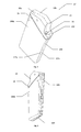
- FIG. 1 shows the front view of the quenching chamber in the first embodiment of the invention, in perspective view,
- FIG. 2 shows the back view of the quenching chamber in the first embodiment of the invention, in perspective view
- FIG. 3 shows the front view of the quenching chamber body in the second embodiment of the invention, in perspective view
- FIG. 4 shows the back view of the quenching chamber body in the second embodiment of the invention, in perspective view
- FIG. 5 shows the front view of the cassette of the quenching chamber in the second embodiment of the invention, in perspective view
- FIG. 6 shows the front view of the quenching chamber in the second embodiment of the invention, in perspective view
- FIG. 7 shows the back view of the quenching chamber in the second embodiment of the invention, in perspective view
- FIG. 8 shows the body of the quenching chamber, in the first embodiment of the invention, without taking into account the arcing contact unit, in a section along the line dividing the body into two symmetrical halves,
- FIG. 9 shows the body of the quenching chamber, in the first embodiment of the invention, together with the arcing contact unit, in a section along the line dividing the body into two symmetrical halves,
- FIG. 10 shows the body of the quenching chamber, in the second embodiment of the invention, together with the arcing contact unit, in a section along the line dividing the body into two symmetrical halves,
- FIG. 11 shows the quenching chamber from FIG. 2 , in section A-A in a plane parallel to the top wall of the body,
- FIG. 12 shows the quenching chamber from FIG. 7 , in section B-B in a plane parallel to the top wall of the body.
- the quenching chamber 1 in the first embodiment of the invention and in the first version of this embodiment is formed in the shape of a solid of a gassing material, which solid has a shape similar to a rectangular prism with a top wall 2 , a bottom wall 3 , a front wall 4 , a back wall 5 and two side walls 6 a and 6 b .
- the dashed line indicates that the quenching chamber can be made in the second version of the embodiment in the form of two symmetrical halves permanently joined with each other by screwing. Assembly openings in the side walls are indicated by the symbols of a circle and a cross in the drawing.
- the side walls 6 a and 6 b in both versions of the first embodiment of the invention have holders 7 a and 7 b situated near the bottom wall 3 , opposite to each other in a mirror image position.
- the holders 7 a and 7 b are used to fix the quenching chamber 1 to a post insulator of the switch disconnector, not shown in the drawing, and they are provided with assembly openings, indicated by the symbols of a circle and a cross in the drawing.
- an outlet 8 intended for letting out gasses from the inside of the quenching chamber is longitudinally situated.
- inlet/outlet 10 of the arcing knife of the switch disconnector which knife can be made from a bar, or flat sheet metal, or a flat bar and it moves inside the quenching chamber by means of a revolving mechanism of the switch disconnector, not shown in the drawing, according to the knife trajectory designed for the given type of switch.
- the quenching chamber 1 comprises a body 11 preferably made from two shaped plates 11 a and 11 b joined non-permanently and adhering to each other with the larger surfaces basically parallel to side walls 6 a and 6 b .
- the non-permanent joining of the plates 11 a and 11 b is achieved by screwing the two plates with each other through assembly openings, indicated by symbols in the drawing.
- the body 11 ′ does not have the holders 7 a and 7 b and it is located in a casing forming a cassette 12 , and the volume of the solid which is the body 11 ′ is significantly reduced as a result of cutting a layer of the material of the body off the walls 2 , 3 , 4 , 5 , 6 a and 6 b of the body 11 and creating new walls, i.e. a top wall 202 , a bottom wall 203 , a front wall 204 , a back wall 205 and two side walls 206 a and 206 b .
- the thickness of the cut-off layers can be different for individual walls.
- the body 11 ′ can be made in the first version in the form of a solid or in the second version in the form of two symmetrical halves permanently joined with each other by screwing, which is indicated in the drawing by the dashed line.
- the top wall 202 has a spline 13 which can be made as an openwork structure. Below the spline 13 in the body 11 ′ there is a groove 15 used to fix a gasket 16 .
- the inlet/outlet 10 of the arcing knife in the second embodiment of the invention is situated in the body 11 ′ at the base of the spline 13 , in the top wall 202 .
- the body 11 ′ is formed of two shaped plates 11 ′ a and 11 ′ b , non-permanently connected, adhering to each other with the larger surfaces, basically parallel to the side walls 206 a and 206 b .
- the spline 13 consists of halves 13 a and 13 b which are elements of the plates 11 ′ a and 11 ′ b , respectively, and they are situated symmetrically relative to each other forming a mirror image.
- the splines 13 a and 13 b are used to non-permanently join the plates 11 ′ a and 11 ′ b with each other and they can be made as an openwork structure consisting of internal ribs 13 c .
- the ribbings 13 c reduce the weight of the quenching chamber.
- the cassette 12 comprises external walls, i.e. a top wall 2 ′, a bottom wall 3 ′, a front wall 4 ′, a back wall 5 ′ and two side walls 6 ′ a and 6 ′ b , corresponding exactly to the walls 2 , 3 , 4 , 5 , 6 a and 6 b of the body 11 .
- Internal walls of the cassette 12 correspond exactly to the walls of the body 11 ′ after the cutting-off, i.e. they correspond to the bottom wall 203 , the front wall 204 , the back wall 205 and the side walls 206 a and 206 b .
- the side walls 6 ′ a and 6 ′ b of the cassette 12 are provided with holders 7 ′ a and 7 ′ b which are situated near the bottom wall 3 ′, opposite to each other in a mirror image position.
- the holders 7 ′ a and 7 ′ b correspond to the side holders 7 a and 7 b and they are used to fix the cassette 12 to the post insulator of the switch disconnector, not shown in the drawing, and they are provided with assembly openings, marked by the symbols of a circle and a cross in the drawing.
- the cassette 12 is provided with a cassette opening 14 which is located in the top wall 2 ′ of the cassette, through which the body 11 ′ is inserted inside the cassette 12 .
- the back wall 5 ′ of the cassette 12 In the middle of the back wall 5 ′ of the cassette 12 there is a longitudinally situated outlet 8 ′ coinciding with the opening 8 of the body 11 , intended to let out gasses from the inside of the quenching chamber 1 .
- a port 9 ′ for the electric connection of the quenching chamber 1 , which coincides with the port 9 in the body 11 .
- the cassette 12 is made as a resin casting.
- the cassette 12 after the body 11 ′ is slid inside it, is a solid of a shape and volume corresponding to the shape and volume of the body 11 . Owing to this, the quenching chamber in both embodiments of the invention can be used for identical switch disconnectors.
- the second embodiment of the invention additionally makes it possible to replace the body 11 ′ of the chamber after repeated tripping of the switch disconnector, without the need to dismount the cassette 12 from the switch insulator, not shown in the drawing.
- the body 11 or 11 ′ contains an arcing knife channel 17 hollowed inside it and extending from the inlet of the arcing knife 10 to a socket 18 hollowed in the body 11 or 11 ′ and used to fix an arcing contact unit 19 in it.
- the channel 17 has a longitudinal axis which is a circular arc of a radius compatible with the circular arc of the trajectory of the arcing knife of the switch disconnector, not shown in the drawing.
- the channel has the cross-section in the shape of a circle, and for an arcing knife made from sheet metal or from a flat bar it has the shape of a rectangle.
- the socket 18 is made by hollowing out the material in the body 11 or in the body 11 ′ and it is situated perpendicular to the back wall 5 or 205 .
- the socket 18 houses the arcing contact unit 19 .
- the socket 18 is connected with the port 9 or 9 ′ of the switch disconnector connection, not shown in the drawing.
- a groove 20 used to fix a gasket 21 used to seal the connections between the arcing contact unit 19 and the electric connection of the switch disconnector, not shown in the drawing, which connection is inserted through the port 9 or 9 ′.
- An arc channel 22 which forms a flat funnel whose height h, in a plane parallel to the surfaces of the side walls 6 of the body 11 or 6 ′ of the cassette 12 , respectively, decreases with the increase in the distance to the arcing knife channel 17 , extends directly along the length of the arcing knife channel 17 , from the back wall 5 or 205 of the chamber 1 .
- the arc chamber 22 is connected with the inside of the arcing knife channel 17 through a gap of a width s, preferably, of a constant width less than the width of the arcing knife channel 17 measured in a plane perpendicular to the surfaces of the side walls 6 of the body 11 or 6 ′ of the cassette 12 of the quenching chamber 1 .
- the arc chamber 22 ends with an outlet 23 .
- the outlet 23 is connected with the blow-out channel 24 which for the first embodiment of the invention extends from the end of the arc chamber 22 to the gas outlet 8 and which is made in the body 11 .
- the blow-out channel 24 ′ extends from the end of the arc chamber 22 to the gas outlet 8 ′ made in the cassette 12 .
- the outlet 8 , 8 ′ in both embodiments has the shape of an elongated gap made in the back wall 5 of the body 11 , or in the wall 5 ′ of the cassette 12 .
- the height H of the blow-out channel 24 or the height H′ of the blow-out channel 24 ′ measured in a plane parallel to the surfaces of the side walls 6 of the body 11 or the side walls 6 ′ of the cassette 12 , increases with the distance to the outlet 23 of the arc chamber 22 .
- the width G of the blow-out channel 24 or the width G′ of the blow-out channel 24 ′ measured in a plane perpendicular to the surfaces of the side walls 6 of the body 11 or the side walls 6 ′ of the cassette 12 , increases with the distance to the arc chamber 22 .
- the arc chamber 22 has grooves 25 to increase the active gassing surfaces of the body 11 or 11 ′, which are arranged longitudinally to the direction of the outlet gasses from the arcing knife channel 17 .
- the arcing knife channel 17 and the arc chamber 22 form an arc channel of the quenching chamber 1 .
- the length of the arcing knife channel 17 is designed, taking into account the speed of the arcing knife inside the channel 17 , to complete the arc quenching process before the moment of exit of the arcing knife from the arcing knife outlet 10 and, at the same time, to prevent a spontaneous reignition of the arc between the arcing knife and the arcing contact unit 19 after the exit of the arcing knife from the outlet 10 .
- the function of the quenching chamber is to quench the electric arc produced as a result of switching processes of a medium voltage switch disconnector.
- the process of interruption of currents that is executed in the quenching chamber consists in assisting in the quenching of the electric arc which is initiated at the moment of exit of the arcing knife from the arcing contact in specific voltage conditions.
- the assistance in the arc quenching consists in cooling, lengthening and flattening the electric arc.
- the cooling process is executed by gassing the material of the arc channel formed of the arcing knife channel 17 and of the arc chamber 22 .
- the effectiveness of the cooling process is improved by intensification of the gassing process in the arc chamber 22 as a result of an increase in the active surface of the gassing plates, which is achieved by grooving the grooves 25 in the surfaces of the arc chamber 22 .
- the lengthening process is executed by pushing the arc out of the space of the arcing knife channel 17 to the arc chamber 22 owing to the limited volume of the arcing knife channel 17 and owing to the pressure which is generated there as a result of gassing of the gassing surfaces.
- the flattening of the arc is executed by the fact that the arc column pushed out of the arcing knife channel 17 to the arc chamber 22 has to adjust to the dimensions of the arc chamber 22 , and more precisely, it is a result of pushing the arc column out into the arc chamber 22 space restricted by the width s of the gap.
- the flattening of the arc column causes that the gassing process is more effective due to an increase in the area of adherence of the arc column to the active gassing surface.
- the intensity of the above described electric arc quenching processes in the chamber depends on the switching current intensity, which causes that the process of overload current interruption differs from the process of work current interruption, and the difference is the consequence of different current values and thus of different values of pressure generated within the arcing knife channel 17 , before the knife exits the channel 17 , as a result of gassing of active surfaces.
- the design of the arcing knife channel 17 and of the blow-out channel 24 according to the invention ensures that both in the process of overload current interruption and in the process of work current interruption the arc column is pushed outside the arcing knife channel 17 . For overload currents, the arc column is pushed into the arc chamber 22 farther from the arcing knife channel 17 than is the case for work currents.
- the distance to which the arc column is pushed depends on the value of pressure generated within the arcing knife channel 17 .
- the arc column is pushed into the arc chamber 22 which has a funnel-like shape, the arc column is lengthened, which helps the quenching process. Cooling, lengthening, and flattening of the arc column helps the quenching process.
Landscapes
- Arc-Extinguishing Devices That Are Switches (AREA)
- Circuit Breakers (AREA)
Abstract
Description
- 1—the quenching chamber
- 2 (202)—the top wall of the quenching chamber
- 3 (203)—the bottom wall of the quenching chamber
- 4 (204)—the front wall of the quenching chamber
- 5 (205)—the back wall of the quenching chamber
- 6 (6 a, 6 b) (206 a, 206 b)—the side walls of the quenching chamber
- 7 (7 a, 7 b, 7 a′, 7 b′)—the assembly holders of the quenching chamber
- 8 (8′)—the outlet of the quenching chamber
- 9 (9′)—the port for the electric connection of the switch
- 10—the inlet/outlet of the arcing knife
- 11, 11′ —the body of the quenching chamber
- 11 a, 11 b—the shaped plates of the
body 11 - 11′a, 11′b—the shaped plates of the
body 11′ - 12—the cassette of the
body 11′ - 2′— the external top wall of the cassette
- 3′ —the external bottom wall of the cassette
- 4′ —the external front wall of the cassette
- 5′ —the external back wall of the cassette
- 6′(6 a′, 6 b′)—the external the side walls of the cassette
- 13—the spline of the cassette
- 13 a, 13 b—the halves of the spline of eh cassette
- 13 c—the spline ribs
- 14—the cassette opening
- 15—the groove under the gasket in the cassette
- 16—the cassette gasket
- 17—the arcing knife channel of the switch
- 18—the socket of the arcing contact unit
- 19—the arcing contact unit
- 20—the groove under the gasket the socket of the arcing contact unit
- 21—the gasket of the socket of the arcing contact unit
- 22—the arc chamber
- 23—the outlet of the arc chamber
- 24—the blow-out channel in the
body 11 - 24′—the blow-out channel in the cassette
- 25—the grooves of the arc chamber
- s—the width of the arc chamber gap
- h—the height of the arc chamber funnel
- G, G′ —the width of the blow-out channel
- H, H′ —the height of the blow-out channel
Claims (13)
Applications Claiming Priority (4)
| Application Number | Priority Date | Filing Date | Title |
|---|---|---|---|
| EP12460069 | 2012-09-26 | ||
| EP12460069.3A EP2713383B1 (en) | 2012-09-26 | 2012-09-26 | Quenching chamber of a medium-voltage switch disconnector |
| EP12460069.3 | 2012-09-26 | ||
| PCT/EP2013/002436 WO2014048523A1 (en) | 2012-09-26 | 2013-08-14 | Quenching chamber of a medium-voltage switch disconnector |
Publications (2)
| Publication Number | Publication Date |
|---|---|
| US20150279594A1 US20150279594A1 (en) | 2015-10-01 |
| US9401253B2 true US9401253B2 (en) | 2016-07-26 |
Family
ID=47080403
Family Applications (1)
| Application Number | Title | Priority Date | Filing Date |
|---|---|---|---|
| US14/428,446 Active US9401253B2 (en) | 2012-09-26 | 2013-08-14 | Quenching chamber of a medium-voltage switch disconnector |
Country Status (5)
| Country | Link |
|---|---|
| US (1) | US9401253B2 (en) |
| EP (1) | EP2713383B1 (en) |
| CN (1) | CN104662633B (en) |
| PL (1) | PL2713383T3 (en) |
| WO (1) | WO2014048523A1 (en) |
Citations (9)
| Publication number | Priority date | Publication date | Assignee | Title |
|---|---|---|---|---|
| US2757262A (en) * | 1955-05-23 | 1956-07-31 | Gen Electric | Circuit breaker casing with coated arc extinguishing chamber |
| US3377447A (en) | 1965-03-31 | 1968-04-09 | Gen Electric | Loadbreak for open type cutouts |
| US3452172A (en) | 1965-07-12 | 1969-06-24 | Siemens Ag | Current limiting circuit breaker |
| US3859487A (en) | 1970-06-13 | 1975-01-07 | Siemens Ag | Electric switch for aerodynamic acceleration of a plasma |
| US4393288A (en) * | 1981-06-23 | 1983-07-12 | Gte Products Corporation | Circuit breaker |
| DE19518051A1 (en) | 1995-05-17 | 1996-11-21 | Abb Patent Gmbh | Arc extinguishing device esp. for small modular switch devices e.g. circuit breakers |
| EP0959483A2 (en) | 1998-04-20 | 1999-11-24 | Fritz Driescher KG, Spezialfabrik für Elektrizitätswerksbedarf GmbH & Co. | Load break switch with arc extinguishing chamber |
| US6373016B2 (en) * | 2000-04-10 | 2002-04-16 | Schneider Electric Industries Sa | Pole for a low-voltage limiting electrical power circuit breaker and a circuit breaker equipped with such a pole |
| US20090145882A1 (en) * | 2006-06-12 | 2009-06-11 | Ellenberger & Poensgen Gmbh | Protection Switch |
Family Cites Families (1)
| Publication number | Priority date | Publication date | Assignee | Title |
|---|---|---|---|---|
| ATE501516T1 (en) * | 2008-08-20 | 2011-03-15 | Abb Technology Ag | HIGH VOLTAGE SWITCH WITH COOLING |
-
2012
- 2012-09-26 PL PL12460069T patent/PL2713383T3/en unknown
- 2012-09-26 EP EP12460069.3A patent/EP2713383B1/en active Active
-
2013
- 2013-08-14 US US14/428,446 patent/US9401253B2/en active Active
- 2013-08-14 WO PCT/EP2013/002436 patent/WO2014048523A1/en not_active Ceased
- 2013-08-14 CN CN201380050343.2A patent/CN104662633B/en active Active
Patent Citations (9)
| Publication number | Priority date | Publication date | Assignee | Title |
|---|---|---|---|---|
| US2757262A (en) * | 1955-05-23 | 1956-07-31 | Gen Electric | Circuit breaker casing with coated arc extinguishing chamber |
| US3377447A (en) | 1965-03-31 | 1968-04-09 | Gen Electric | Loadbreak for open type cutouts |
| US3452172A (en) | 1965-07-12 | 1969-06-24 | Siemens Ag | Current limiting circuit breaker |
| US3859487A (en) | 1970-06-13 | 1975-01-07 | Siemens Ag | Electric switch for aerodynamic acceleration of a plasma |
| US4393288A (en) * | 1981-06-23 | 1983-07-12 | Gte Products Corporation | Circuit breaker |
| DE19518051A1 (en) | 1995-05-17 | 1996-11-21 | Abb Patent Gmbh | Arc extinguishing device esp. for small modular switch devices e.g. circuit breakers |
| EP0959483A2 (en) | 1998-04-20 | 1999-11-24 | Fritz Driescher KG, Spezialfabrik für Elektrizitätswerksbedarf GmbH & Co. | Load break switch with arc extinguishing chamber |
| US6373016B2 (en) * | 2000-04-10 | 2002-04-16 | Schneider Electric Industries Sa | Pole for a low-voltage limiting electrical power circuit breaker and a circuit breaker equipped with such a pole |
| US20090145882A1 (en) * | 2006-06-12 | 2009-06-11 | Ellenberger & Poensgen Gmbh | Protection Switch |
Non-Patent Citations (2)
| Title |
|---|
| International Search Report mailed Oct. 31, 2013 in corresponding application No. PCT/EP2013/002436. |
| Written Opinion mailed Oct. 31, 2013 in corresponding application No. PCT/EP2013/002436. |
Also Published As
| Publication number | Publication date |
|---|---|
| PL2713383T3 (en) | 2015-04-30 |
| EP2713383A1 (en) | 2014-04-02 |
| EP2713383B1 (en) | 2014-11-12 |
| US20150279594A1 (en) | 2015-10-01 |
| WO2014048523A1 (en) | 2014-04-03 |
| CN104662633B (en) | 2017-03-08 |
| CN104662633A (en) | 2015-05-27 |
Similar Documents
| Publication | Publication Date | Title |
|---|---|---|
| EP2064717B1 (en) | Arc buffle, and arc chute assembly and electrical switching apparatus employing the same | |
| RU2479060C2 (en) | Arc suppressor and contact breaker equipped with one such arc suppressor | |
| EP3048625B1 (en) | Low voltage switch pole | |
| CN109285704B (en) | Arc extinguishing structure of double-breakpoint contact | |
| KR101657454B1 (en) | Gas isolated circuit breaker | |
| CN101107756B (en) | Surge arrester with two divergent electrodes and a spark gap operating between the electrodes | |
| JP2014229363A (en) | Gas circuit breaker | |
| CN110391117B (en) | Low-voltage circuit breaker | |
| US9401253B2 (en) | Quenching chamber of a medium-voltage switch disconnector | |
| CN109087832B (en) | Small-sized circuit breaker | |
| CN106469623B (en) | circuit breaker | |
| CN119008324A (en) | Contactor and circuit system | |
| US9947495B2 (en) | Arc extinguishing chamber for electrical circuit breaker and circuit breaker comprising such a chamber | |
| US9953789B2 (en) | Single-pole breaking unit comprising a rotary contact bridge, and a switchgear device, and circuit breaker comprising such a unit | |
| EP2866244B1 (en) | Helicoidal switch | |
| JP2019091590A (en) | Gas-blast circuit breaker | |
| JP2005285547A (en) | Circuit breaker arc extinguishing device | |
| CN224096675U (en) | Arc extinguishing system and miniature circuit breaker | |
| EP3644462B1 (en) | Protection device for discharge current with a transverse exhaust direction | |
| DE102017214557B4 (en) | Electromechanical protective switching device | |
| CN223771041U (en) | relay | |
| CN219203078U (en) | Zero arcing cover for molded case circuit breaker | |
| CN224096655U (en) | relay | |
| CN223245500U (en) | Contactor with protection switch and circuit system | |
| CN217544515U (en) | Circuit breaker |
Legal Events
| Date | Code | Title | Description |
|---|---|---|---|
| AS | Assignment |
Owner name: ABB TECHNOLOGY AG, SWITZERLAND Free format text: ASSIGNMENT OF ASSIGNORS INTEREST;ASSIGNORS:PIEKARSKI, PIOTR;DOMURAD, ZBIGNIEW;KOWALSKI, ADAM;REEL/FRAME:035171/0027 Effective date: 20150304 |
|
| FEPP | Fee payment procedure |
Free format text: PAYOR NUMBER ASSIGNED (ORIGINAL EVENT CODE: ASPN); ENTITY STATUS OF PATENT OWNER: LARGE ENTITY |
|
| STCF | Information on status: patent grant |
Free format text: PATENTED CASE |
|
| AS | Assignment |
Owner name: ABB SCHWEIZ AG, SWITZERLAND Free format text: MERGER;ASSIGNOR:ABB TECHNOLOGY LTD.;REEL/FRAME:040622/0001 Effective date: 20160509 |
|
| MAFP | Maintenance fee payment |
Free format text: PAYMENT OF MAINTENANCE FEE, 4TH YEAR, LARGE ENTITY (ORIGINAL EVENT CODE: M1551); ENTITY STATUS OF PATENT OWNER: LARGE ENTITY Year of fee payment: 4 |
|
| MAFP | Maintenance fee payment |
Free format text: PAYMENT OF MAINTENANCE FEE, 8TH YEAR, LARGE ENTITY (ORIGINAL EVENT CODE: M1552); ENTITY STATUS OF PATENT OWNER: LARGE ENTITY Year of fee payment: 8 |