US9401029B2 - Moving object detection method - Google Patents
Moving object detection method Download PDFInfo
- Publication number
- US9401029B2 US9401029B2 US14/638,805 US201514638805A US9401029B2 US 9401029 B2 US9401029 B2 US 9401029B2 US 201514638805 A US201514638805 A US 201514638805A US 9401029 B2 US9401029 B2 US 9401029B2
- Authority
- US
- United States
- Prior art keywords
- images
- moving object
- value
- pixel
- pixel values
- Prior art date
- Legal status (The legal status is an assumption and is not a legal conclusion. Google has not performed a legal analysis and makes no representation as to the accuracy of the status listed.)
- Active
Links
Images


Classifications
-
- G—PHYSICS
- G06—COMPUTING OR CALCULATING; COUNTING
- G06T—IMAGE DATA PROCESSING OR GENERATION, IN GENERAL
- G06T7/00—Image analysis
- G06T7/20—Analysis of motion
- G06T7/277—Analysis of motion involving stochastic approaches, e.g. using Kalman filters
-
- G06T7/204—
-
- B—PERFORMING OPERATIONS; TRANSPORTING
- B64—AIRCRAFT; AVIATION; COSMONAUTICS
- B64G—COSMONAUTICS; VEHICLES OR EQUIPMENT THEREFOR
- B64G3/00—Observing or tracking cosmonautic vehicles
-
- G06T7/0048—
-
- G—PHYSICS
- G06—COMPUTING OR CALCULATING; COUNTING
- G06T—IMAGE DATA PROCESSING OR GENERATION, IN GENERAL
- G06T7/00—Image analysis
- G06T7/20—Analysis of motion
-
- G06T7/2033—
-
- G06T7/208—
-
- G—PHYSICS
- G06—COMPUTING OR CALCULATING; COUNTING
- G06T—IMAGE DATA PROCESSING OR GENERATION, IN GENERAL
- G06T7/00—Image analysis
- G06T7/20—Analysis of motion
- G06T7/246—Analysis of motion using feature-based methods, e.g. the tracking of corners or segments
-
- G—PHYSICS
- G06—COMPUTING OR CALCULATING; COUNTING
- G06V—IMAGE OR VIDEO RECOGNITION OR UNDERSTANDING
- G06V20/00—Scenes; Scene-specific elements
- G06V20/10—Terrestrial scenes
- G06V20/13—Satellite images
-
- G—PHYSICS
- G06—COMPUTING OR CALCULATING; COUNTING
- G06V—IMAGE OR VIDEO RECOGNITION OR UNDERSTANDING
- G06V20/00—Scenes; Scene-specific elements
- G06V20/50—Context or environment of the image
- G06V20/52—Surveillance or monitoring of activities, e.g. for recognising suspicious objects
-
- H—ELECTRICITY
- H04—ELECTRIC COMMUNICATION TECHNIQUE
- H04N—PICTORIAL COMMUNICATION, e.g. TELEVISION
- H04N23/00—Cameras or camera modules comprising electronic image sensors; Control thereof
- H04N23/60—Control of cameras or camera modules
- H04N23/68—Control of cameras or camera modules for stable pick-up of the scene, e.g. compensating for camera body vibrations
- H04N23/681—Motion detection
- H04N23/6811—Motion detection based on the image signal
-
- H—ELECTRICITY
- H04—ELECTRIC COMMUNICATION TECHNIQUE
- H04N—PICTORIAL COMMUNICATION, e.g. TELEVISION
- H04N23/00—Cameras or camera modules comprising electronic image sensors; Control thereof
- H04N23/80—Camera processing pipelines; Components thereof
-
- H04N5/23229—
-
- H04N5/23254—
-
- G—PHYSICS
- G06—COMPUTING OR CALCULATING; COUNTING
- G06T—IMAGE DATA PROCESSING OR GENERATION, IN GENERAL
- G06T2207/00—Indexing scheme for image analysis or image enhancement
- G06T2207/10—Image acquisition modality
- G06T2207/10032—Satellite or aerial image; Remote sensing
-
- G—PHYSICS
- G06—COMPUTING OR CALCULATING; COUNTING
- G06T—IMAGE DATA PROCESSING OR GENERATION, IN GENERAL
- G06T2207/00—Indexing scheme for image analysis or image enhancement
- G06T2207/20—Special algorithmic details
- G06T2207/20076—Probabilistic image processing
-
- G—PHYSICS
- G06—COMPUTING OR CALCULATING; COUNTING
- G06T—IMAGE DATA PROCESSING OR GENERATION, IN GENERAL
- G06T2207/00—Indexing scheme for image analysis or image enhancement
- G06T2207/30—Subject of image; Context of image processing
- G06T2207/30181—Earth observation
-
- G—PHYSICS
- G06—COMPUTING OR CALCULATING; COUNTING
- G06T—IMAGE DATA PROCESSING OR GENERATION, IN GENERAL
- G06T2207/00—Indexing scheme for image analysis or image enhancement
- G06T2207/30—Subject of image; Context of image processing
- G06T2207/30241—Trajectory
-
- G—PHYSICS
- G06—COMPUTING OR CALCULATING; COUNTING
- G06V—IMAGE OR VIDEO RECOGNITION OR UNDERSTANDING
- G06V10/00—Arrangements for image or video recognition or understanding
- G06V10/40—Extraction of image or video features
- G06V10/62—Extraction of image or video features relating to a temporal dimension, e.g. time-based feature extraction; Pattern tracking
Definitions
- the present invention relates to a method of detecting a moving object from captured images.
- Space debris is an out-of-service artificial object which orbits the Earth.
- a detection of the existence of the space debris is important for smooth operation of spacecraft (artificial satellites, space stations, space shuttles and the like).
- One method among conventional space debris detection methods determines the existence of space debris by extracting high-luminance parts respectively from images captured by a CCD (charge coupled device) camera on the Earth or on the orbit.
- CCD charge coupled device
- This method includes: cropping areas in the same size from three or more images captured at time intervals in accordance with the movement of a moving object such as space debris; and applying a stacking method to the cropped image areas.
- the movement of the moving object is the uniform motion or the like having mobile vectors (velocities) in a two-dimensional direction in the xy-coordinate system, for example.
- the cropped image areas are superposed on one another, and a median value is evaluated from pixel values at the same pixels across the superposed image areas. If the median value thus evaluated is equal to or greater than a predetermined value, the pixel is extracted as a pixel representing the existence of the moving object (see Japanese Patent Application Laid-open Publications Nos. 2002-139319 and 2003-323625, for example).
- the stacking method is a widely-used effective method not only for detecting space debris, but also for detecting a moving object at a low luminance level in an image. Furthermore, as described above, the stacking method employs the median pixel value as the evaluation value for the moving object detection. Therefore, the stacking method causes no rise in the evaluation value even if a noise component happens to be captured in some of the images (for example, a star or a cosmic ray in the cosmic space is captured in some of the images), in contrast to another case in which an average pixel value is used as the evaluation value. For this reason, the stacking method is advantageous in inhibiting erroneous detection of a moving object due to the existence of a star or a cosmic ray which happens to be captured therein.
- the moving object when the moving object is detected from the multiple images captured at time intervals using the stacking method, it is required to superpose the areas to be cropped from the respective images in a staggered manner by the amount of movement of the moving object in each image-photographing (image-capturing) interval so that objects captured in the images, which correspond to the detection object, are overlapped one another.
- image-capturing image-capturing
- the processing of evaluating a median value from pixel values at the same pixel positions across the n images needs to include: an arithmetic process of sorting the n pixel values; and a process of selecting a value lying at the middle point in a series of the pixel values arranged in an ascending (or descending) order as a result of the sorting.
- the time needed for the calculation depends on the calculation needed for the sorting, and equals to the time needed to perform n log(n) comparison processes and assignment operations.
- the number of operations needed for the comparison processes and the assignment operations is log(n) times the number (n) of operations to be performed to evaluate a simple average pixel value.
- the values as a result of a comparison operation need to be sorted, and three assignment operations are additionally needed each time the values are sorted. For this reason, the number of operations needed for this processing is several times larger. This makes the processing become a heavily time-consuming task.
- the processor performs a speculative execution after a comparison process. That is, after comparing a pair of pixel values selected from the n pixel values, the processor performs a speculative execution of “changing the order of the two pixel values” depending on the result of the comparison, or a speculative execution of “not changing the order of the two pixel values.”
- the processor performs the speculative execution of “changing the order of the two pixel values.” If the pixel values, as the object of the speculative execution, happen to be arranged in an ascending or descending order, reverse to an order in which the processor sorts the two pixel values, the speculative execution performed by the processor is a success.
- the speculative execution performed by the processor is a failure because: the processes following the speculative execution have to be suspended; the preceding work (the work based on the wrong result) has to be undone; and the preceding processes have to be resumed.
- the speculative execution is performed on the assumption that a branch which is the same as that as a result of the previous execution will take place, and in a way that the process following the speculative execution is carried out by determining the contents of the execution before the conditions are settled.
- the pixel values are arranged in a random order, there is a 50% probability that the result of the previous comparison is followed by the same result. For this reason, there is a 50% probability that the speculative execution performed by the processor ends in failure.
- the method using the median value of the pixel values at the same pixel positions across the n images as the evaluation value for detecting the moving object is greatly advantageous in improving the detection accuracy, as compared with the method using the average value.
- the processor has to perform an enormous amount of arithmetic processing in order to evaluate the median value, as compared with evaluating the average value.
- An object of the present invention is to provide a moving object detection method capable of accurately detecting a moving object or a candidate therefore using a stacking method with less operation processes than required when an evaluation value for the moving object detection is evaluated from pixel values at the same pixel positions across captured images with all of the captured images superposed one on another at one time.
- An aspect of the present invention provides a method (a moving object detection method) for detecting a moving object being an observation object from images captured in constant intervals, based on an evaluation value obtained from pixel values at the same pixel positions overlapping one another across the images by sequentially moving the images in accordance with a content corresponding to an estimated movement content of the moving object being the observation object during the constant intervals.
- the method includes: a judgment step of dividing the images into groups each including a predetermined number of images successive in time series, and for each group, judging whether or not each pixel is a candidate for a pixel capturing the moving object being the observation object based on the evaluation value obtained from the pixel values at the same pixel positions overlapping one another across the predetermined number of images by sequentially moving the images in accordance with the content corresponding to the estimated movement content; a check step of checking whether or not each group includes candidates for the pixel capturing the moving object being the observation object which coincide with one another in terms of the estimated movement content and a movement locus; and a detection step of detecting the moving object being the observation object in each image from the candidates for the pixel capturing the moving object being the observation object in each group which are confirmed to coincide with one another in terms of the estimated movement contents and movement locus.
- the evaluation value may be evaluated, using a robust statistics on the assumption that there is no large difference among the pixel values, from the pixel values at the same pixel positions overlapping one another across the predetermined number of images by sequentially moving the images in accordance with the content corresponding to the estimated movement content.
- the judgment step may judge the pixels at the same pixel positions across the images as the candidates for the pixel capturing the moving object being the observation object, if the evaluation value obtained using the robust statistics is equal to or greater than a criterion value.
- the method may further include: an average-value-of-limited-pixels calculating step of, for each group, calculating an average value of pixel values which are equal to or less than a threshold value for distinguishing the moving object being the observation object from a light emitting element with a higher luminance than that of the moving object, the pixel values being among the pixel values at the same pixel positions across the predetermined number of images.
- the judgment step may judge the pixels at the same pixel positions across the images as the candidates for the pixel capturing the moving object being the observation object if the average value calculated in the average-value-of-limited-pixels calculating step is equal to or greater than a criterion value.
- the method may further include: an average-value-of-all-pixels calculating step of, for each group, calculating an average value of all the pixel values at the same pixel positions across the images; and a threshold value calculating step of, for each group, calculating the threshold value by multiplying the average value calculated in the average-value-of-all-pixels calculating step by a predetermined number.
- the estimated movement content may be uniform linear motion of the moving object being as observation object in an estimated movement direction thereof and with an estimated movement amount thereof.
- the moving object as the observation object may be detected from the images based on the evaluation value obtained from the pixel values at the same pixel positions overlapping one another across the images by sequentially moving the images by parallel displacement in the estimated movement direction of and with the estimated movement amount of the moving object being the observation object.
- the estimated movement content may be uniform acceleration motion of the moving object being the observation object in an estimated movement direction thereof and with an estimated movement amount thereof which increases or decreases by a constant amount over time.
- the moving object being the observation object may be detected from the images based on the evaluation value obtained from the pixel values at the same pixel positions overlapping one another across the images by sequentially moving the images by parallel displacement in the estimated movement direction of and with the estimated movement amount of the moving object being the observation object.
- the moving object being the observation object may be an object orbiting the earth.
- the images may be images captured in intervals during fixed-point observation.
- the present invention makes it possible to accurately detect a moving object using a stacking method with less operation processes than required when an evaluation value for the moving object detection is evaluated from pixel values at the same pixel positions across captured images with all of the captured images superposed one on another at one time.
- FIG. 1 is a flowchart showing a procedure in the case where a moving object detection method of the present invention is applied to detection of space debris from photographed astronomical images.
- FIG. 2 is a flowchart showing a concrete procedure for a photographing (capturing) and image reading process step in the flowchart shown in FIG. 1 .
- FIG. 3 is a flowchart showing a concrete procedure for a preliminary process step in the flowchart shown in FIG. 1 .
- FIG. 4 is a flowchart showing a concrete procedure for a stacking process step in the flowchart shown in FIG. 1 .
- FIG. 5 is a flowchart showing a concrete procedure for a continuity evaluation process step in the flowchart shown in FIG. 1 .
- FIG. 6 is an explanatory diagram schematically showing contents of the procedure for the continuity evaluation process step shown in FIG. 5 .
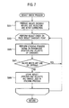
- FIG. 7 is a flowchart showing a concrete procedure for a result check process step in the flowchart shown in FIG. 1 .
- the moving object detection method of the embodiment is designed to detect space debris as a moving object being an observation object from the photographed celestial images.
- this method is designed to perform a photographing (capturing) and image reading process step (step S 1 ), a preliminary process step (step S 3 ), a stacking process step (step S 5 ), a continuity evaluation process step (step S 7 ) and a result check process step (step S 9 ).
- the photographing and image reading process step begins with repeatedly making a series of photographs of a space (the sky), including the geostationary orbit of space debris, for a predetermined length of exposure time at constant time intervals (step S 11 ). Subsequently, the image reading process step (step S 1 of FIG. 1 ) ends with capturing image signals representing the captured images (step S 13 ).
- a photographing (capturing) apparatus (not illustrated) formed by connecting a CCD camera to an astronomical telescope, for example, may be used for taking the images of the sky. Furthermore, in the embodiment, the below-described stacking process step (step S 5 in FIG. 1 ) is carried out p times, each time by using m images. In other words, the p ⁇ m images are photographed in succession by, and captured into the photographing apparatus.
- the preliminary process step begins with making corrections to the image signals, captured from the photographing apparatus (not illustrated), by removing noise components included in the image signals (step S 31 ).
- the size of images representing the corrected image signals is reduced to an image size to be handled in the below-described stacking process step (step S 5 in FIG. 5 ) (step S 33 ).
- the size of the images is reduced to a half in both the vertical and horizontal directions (to a quarter in terms of the area). Then, the largest pixel value in the 2 ⁇ 2 pixels before the reduction is assigned as a pixel value to one pixel after the reduction.
- the preliminary process step (step S 3 in FIG. 1 ) is terminated.
- step S 31 the corrections are made by removing the noise components. Specifically, the corrections are achieved by removing the noise components included in the signals representing the images captured by the photographing apparatus (not illustrated).
- a typical example of the noise components to be removed is an offset component of a CCD element in the CCD camera in the photographing apparatus.
- the offset component of the CCD element is a noise component which occurs when an image of a photographic object captured by the astronomical telescope of the photographing apparatus (not illustrated) is converted into an electric signal by the CCD element in the CCD camera.
- the CCD element may, in some cases, shift (offset) an actual output from the point zero.
- the contents of the offset vary from one CCD element to another.
- the offset component of the CCD element is corrected (i.e., subjected to offset correction) in order that the image signal outputted from the photographing apparatus becomes “0.”
- the offset correction of this case is termed as dark correction.
- the correction value can be obtained by evaluating a value of the output from the CCD element at the time of photographing while blocking the light receiving unit from light.
- the correction value thus evaluated is subtracted from the pixel value at each of the pixels which corresponds to an image of the sky photographed by the photographing apparatus for the moving object detection. This makes it possible to correct the offset component of the CCD element.
- noise component attributed to a star Another typical example of the noise components to be removed from the image signals in step S 31 is a noise component attributed to a star.
- the noise component attributed to the star occurs when the star existing in the sky is captured into the images with the star and its surrounding area expressed as blurred dots or lines in accordance with the moving velocity of the star.
- the noise component attributed to the star can be eliminated from each image by subtracting the pixel values at the same pixel positions in two images that are overlapped each other by parallel displacement with the already-known amount of movement of the star in the already-known movement direction of the star.
- one of the two images is an image captured by the photographing apparatus (not illustrated), and another image is its preceding or following image captured in succession by the photographing apparatus.
- the noise component of the image signals attributed to the star is eliminated after the dark correction to the offset component of the CCD element by: superposing each two successive images of the sky captured by the photographing apparatus for the moving object detection by moving the two successive images by parallel displacement in accordance with the direction and amount of the movement of the star; and subtracting the pixel values at the pixels overlapping each other.
- the foregoing may be employed as the contents of the correction to be made by removing the noise components in step S 31 of FIG. 3 .
- the process of extracting the candidate for the space debris from the m images is achieved by performing calculation using the pixel values at the same pixel positions overlapping one another while, by parallel displacement, sequentially moving each image by its estimated moving velocity of the space debris (i.e., a length (distance or interval) of the movement of the space debris on the image at its estimated moving velocity within a predetermined time length).
- a length (distance or interval) of the movement of the space debris on the image at its estimated moving velocity within a predetermined time length Sequentially changing the estimated moving velocity of the space debris in a range of ( ⁇ Vx/p, ⁇ Vy/p) to (Vx/p, Vy/p)
- this calculation is performed on each estimated moving velocity (step S 53 ).
- the reason why the range of the estimated moving velocity is 1/p is that: the time length is 1/p; and the distance of the movement within the entire time length is also 1/p.
- the calculation using the pixel values at the same pixel positions overlapping one another across the m images is performed for each of pixel positions (whose pixel coordinates are (0, 0) to (Lx, Ly)) of each image.
- an averaging process is performed on the pixel values of the pixels, excluding the pixel values of pixels (outliers) not satisfying a condition, at the same pixel positions overlapping one another across the m images which are sequentially moved by parallel displacement by the estimated moving velocity V of the space debris (step S 55 ).
- the condition means “being less than a threshold value obtained by multiplying the average value of the pixels values of the pixels by a predetermined number.”
- the threshold value is used to distinguish the space debris from an object which emits light at a higher luminance than the space debris (corresponding to a high-luminance light emitting element in the CLAIMS). What value the threshold value should be set at is a very important parameter for a value calculated by the following process to reflect less of the luminance (pixel value) of a moving object whose luminance (pixel value) greatly differs from the luminance of the space debris.
- the threshold value is set based on the average value of all the pixel values at the same pixel positions across the superposed images (by multiplying the average value of all the pixel values by the predetermined number).
- the employment of the threshold value as a criterion for the luminance (pixel value) of the space debris makes it possible to accurately distinguish a pixel whose luminance (pixel value) greatly differs from the criterion luminance (pixel value) , as a pixel representing the existence of a light emitting object which is not the space debris, from a pixel representing the existence of the space debris.
- predetermined number that dominates the threshold value can be set at an appropriate value using a statistical method.
- the predetermined value may be set in a range of 1.5 to 3, for example. The following descriptions will be provided for the embodiment in which the predetermined number is set at 2.
- step S 59 pixels whose pixel values are equal to or less than the threshold value are selected.
- An average value of the pixel values of the selected pixels is calculated (step S 61 ). It should be noted that the average value calculation in step S 61 is judged as being impossible if the proportion of pixels whose pixel values are equal to or less than 0.5 times the average value evaluated in step S 57 to all the pixels exceeds 50%.
- step S 55 the calculation using the pixel values at the same pixel positions overlapping one another across the superposed m images is performed on each of the pixel positions (whose pixel coordinates are (0, 0) to (Lx, Ly)) (step S 55 to step S 61 ).
- step S 53 each time the estimated moving velocity V of the space debris used to sequentially move the m images by parallel displacement is changed from one to another in a range of ( ⁇ Vx/p, ⁇ Vy/p) to (Vx/p, Vy/p) (step S 53 ), an estimated moving velocity V under which the average value evaluated in step S 61 is the largest is selected (or updated) (step S 63 ).
- step S 51 to S 63 the stacking process step (step S 5 in FIG. 1 ) is terminated.
- a median value or an average value of the pixel values at the same pixel positions overlapping one another across the m images may be evaluated as the evaluation value for the space debris detection instead of evaluating the evaluation value based on the averaged value of the pixel values at the same pixel positions overlapping one another across the m images.
- the continuity evaluation process step begins with detecting pixels whose pixel values are equal to or greater than a threshold value (a candidate criterion value, corresponding to a criterion value in the CLAIMS) required for determining a candidate for the space debris, as candidate points for the space debris (step S 71 ).
- a threshold value a candidate criterion value, corresponding to a criterion value in the CLAIMS
- these pixels also represent the pixels, with which the average value of their pixel values evaluated in step S 61 based on the estimated moving velocity V selected in step S 63 becomes the largest.
- two arbitrary groups (q, r ⁇ [1, p]) are selected from the p groups (step S 73 ). For each group q, r, it is calculated as to which pixel in each image the candidate for the space debris detected in step S 71 passes through at common predetermined time (step S 75 ).
- pairs each consisting of a candidate for the space debris from the group q and a candidate for the space debris from the group r, which pass through the same pixel positions (or alternatively, adjacent pixel positions within given ranges) at the predetermined time are extracted (step S 77 ).
- a schematic diagram in FIG. 6 shows that, of three candidate points for the space debris captured in an uppermost image in the lower group in the diagram, two are situated on extension lines from the loci of the movement of two of three candidate points for the space debris captured in each image of in the upper group in the diagram. For this reason, the two candidate points correspond to the pair passing through the same pixel positions at the predetermined time.
- a pair of candidates for the space debris whose estimated moving velocities V in the respective groups q, r are close to each other (i.e., fall within a given error range) are extracted as final candidates for the space debris (step S 79 ).
- a schematic diagram in FIG. 6 shows that: the candidate points for the space debris marked with “OK: coincident in positional direction” are in the same positional direction in both the upper and lower groups in the diagram. For this reason, this pair corresponds to a pair sharing the same estimated moving velocity V inclusive of the directional components.
- the candidate points for the space debris marked with “NG: different in movement direction” are different from each other in the movement direction between the upper and lower groups in the diagram. For this reason, this pair does not correspond to the pair sharing the same estimated moving velocity V inclusive of the directional components.
- the candidate points for the space debris marked with “NG: different in position” are in the same movement direction in both the upper and lower groups in the diagram.
- the candidate point for the space debris captured in the uppermost image in the lower group in the diagram is not situated on the extension line from the movement locus of the candidate point for the space debris captured in the images in the upper group in the diagram. For this reason, this pair does not correspond to the pair passing through the same pixel position at the predetermined time.
- estimated luminances c of the candidates for the space debris from the groups q, r extracted in step S 77 are calculated in step S 79 .
- step S 73 to step S 79 final candidates for the space debris are extracted from another pair of groups, and their luminances c are calculated.
- the final candidates for the space debris are extracted from Groups 1 , 2 , and from Group 2 , 3 ; and their luminances c are calculated.
- the final candidates for the space debris may further be extracted from Groups 1 , 3 , and their luminances c may be calculated as well.
- the continuity evaluation process step (step 7 in FIG. 1 ) is hence terminated.
- step S 9 in FIG. 1 for all the pairs extracted in step S 77 as the final candidates for the space debris, the m images before the size reduction in step S 33 of FIG. 3 but after the correction in step S 31 of FIG. 3 are firstly prepared from each of the groups to which the pairs belong (step S 91 ). Subsequently, using the thus-prepared images, each final candidate is checked on whether or not it should be detected as the space debris (step S 93 ).
- the stacking process to be performed in the stacking process step in step S 5 of FIG. 5 is performed on the final candidate for the space debris by use of the images before the size reduction which are prepared in step S 91 (step S 95 ).
- the pixel value of the candidate for the space debris from each of the groups corresponding to the final pair of candidates for the space debris is set at the estimated luminance c calculated in step S 79 of FIG. 5 .
- the candidate criterion value corresponding to the criterion value in the CLAIMS
- the threshold value the candidate criterion value, corresponding to the criterion value in the CLAIMS
- both the brightness at the candidate point and the brightness of its adjacent pixels are used as the criteria for making the judgment on the space debris. It should be noted, however, that the judgment may be made on the space debris based on either brightness.
- step S 9 in FIG. 1 the result check process step
- step S 71 in FIG. 5 concerning the embodiment corresponds to a judgment step in the CLAIMS.
- the processes from step S 7 through step S 9 in the flowchart of FIG. 1 concerning the embodiment correspond to a detection step in the CLAIMS.
- the process in step S 61 in the flowchart of Fig. concerning the embodiment corresponds to an average-value-of-limited-pixels calculating step in the CLAIMS.
- step S 57 in FIG. 4 concerning the embodiment corresponds to an average-value-of-all-pixels calculating step in the CLAIMS.
- step S 59 in FIG. 4 concerning the embodiment corresponds to a threshold value calculating step in the CLAIMS.
- the captured images are divided into the p groups each including the m successive images, and for each group, the stacking process step using the stacking method in step S 5 in FIG. 1 is performed on the m images. Thereafter, for each group, the continuity evaluation process step in FIG. 5 judges, using the coincidence or proximity in the movement direction or moving velocity as a criterion, whether or not the candidates for the space debris extracted in the stacking process step in FIG. 5 can be adopted as final candidates for the space debris.
- the average value of the pixel values equal to or less than the threshold which is selected in step S 59 in FIG. 4 , is evaluated like in step S 61 in FIG. 4 .
- the estimated number of moving velocities V of the moving object (the distance that the moving object moves in the time period corresponding to the overlaps) is reduced to a half of the number of moving velocities V of the moving object which is estimated when the operation processes are not divided into the halves.
- ( ⁇ Vx/2) ⁇ ( ⁇ Vy/2) moving velocities V can be estimated.
- the set of operation processes are performed on the 32 images twice.
- the above-given number of operation processes is multiplied by 64.
- the needed number of operation processes is approximately 1.0 ⁇ 10 ⁇ 13 (which is a quarter of the number of operation processes which is needed when the operation processes are not divided into the halves to be performed on the respective two groups).
- the detection of candidate points for the space debris using the stacking method is performed on each group. For each group, whether or not each of the candidate points represents the space debris is judged based on the coincidence in the movement amount and the movement locus among the candidate points.
- this makes it possible to accurately detect candidates for pixels capturing the space debris, and consequently the space debris itself, with less operation processes than required when the evaluation value for the space debris detection is evaluated from the pixel values of the same pixel positions across the captured images with all of the captured images superposed one on another at one time.
- the captured images are divided into the groups and the stacking process step is performed on each group, the judgment on whether or not the candidates for the space debris detected from each group are continuous to one another in terms of the movement direction, moving velocity and moving position can be added to the judgment on whether or not the candidates for the space debris represent the space debris.
- the space debris can be accurately detected even though the average pixel value requiring the less operation processes is used as the evaluation value for the space debris detection.
- the average value or an evaluation value based on the average value is employed instead of the median value
- This failure probability is far lower than the 50% probability that the speculation execution ends in failure when the median value is evaluated through the n log(n/p) comparison processes and assignment operations. This makes the probability of unnecessary. operation processes due to the failure in the speculative execution far lower than when the median value is calculated. For this reason, the load of the operation processes can be further reduced.
- the threshold value obtained by multiplying the average value of the pixel values at the same pixel positions across the superposed images by the predetermined number is used to distinguish the space debris from an object which emits light at a higher luminance than the space debris (corresponding to the high-luminance light emitting element in the CLAIMS).
- the average pixel value reflects less of the luminance (pixel value) of the high-luminance light emitting element (noise component), such as a star or a cosmic ray in the cosmic space captured in pixels, than the average value evaluated by simply averaging the pixel values at the same pixel positions across the superposed images.
- the average value evaluated by averaging only the pixel values which are equal to or less than the threshold value obtained by multiplying the average value of the pixel values at the same pixel positions across the superposed images by the predetermined number (two, for example) is closer to the luminance (pixel value) of the space debris than is the average pixel value obtained by simply averaging the pixel values at the same pixel positions across the superposed images.
- the employment of the average value of the pixel values equal to or less than the threshold value as the evaluation value for the space debris detection makes it possible to accurately detect a candidate for a pixel capturing the space debris, and consequently the space debris itself, with less operation processes than required when the median value evaluated from the pixel values at the same pixel positions across the superposed images is used as the evaluation value for the space debris.
- a statistical value such as the average value of the pixel values of the same pixel positions across the superposed images, be used when as described above, the evaluation value for detecting the space debris or candidate points for the space debris is calculated from the pixel values at the same pixel positions across the superposed images. It is further desirable that the points corresponding to the pixel values equal to or greater than the threshold value, which are evaluated using the median value or a robust statistics method with outlier values taken into consideration, such as the RANSAC estimation method or the LMedS estimation method, be detected as candidate points for the space debris.
- the above-mentioned threshold value may be determined independently of the average value of the pixel values at the same pixel positions across the superposed images. Moreover, the threshold value like this does not have to be used.
- the present invention is broadly applicable to the detection of a moving object other than the space debris from images captured in constant intervals using the stacking method, for example, the identification and detection of an object other than the space debris, such as an artificial satellite orbiting the earth, or colored microbes, on captured images.
- the foregoing descriptions have been provided for the embodiment while citing the example of performing the stacking method on the moving object, the observation object, in uniform linear motion on the images in the estimated movement direction and with the estimated movement amount.
- the present invention is applicable, as well, to a case of performing a stacking method on a moving object, an observation object, in uniform acceleration motion on the images with the estimated movement amount which increases or decreases by a constant amount over time.
- the images captured in constant intervals are divided into the groups each including the predetermined number of images successive in time series. If in each group, the candidates judged to represent the moving object, the observation object, in the respective images coincide with one another in terms of the estimated movement contents (estimated motion parameters) and movement locus, the candidates are judged as representing the same moving object. Thereby, the moving object, the observation object, is finally recognized and detected.
- the moving object since the evaluation value for the moving object, the observation object, is evaluated using the stacking method to be performed on each of the groups into which the captured images are divided, the moving object can be accurately detected with less operation processes than required when the evaluation value for the moving object detection is evaluated from the image values at the same pixel positions across the captured images with all of the images superposed one on another at one time.
- the average value calculated in the average-value-of-limited-pixels calculating step is the average value of the pixel values at the same pixel positions across the images, excluding a pixel value corresponding to the high-luminance light emitting element whose luminance (pixel value) is greatly higher than the luminance (pixel value) of the moving object, the observation object, on the images.
- the average value calculated in the average-value-of-limited-pixels calculating step is the average pixel value which reflects less of the luminance (pixel value) of the high-luminance light emitting element (noise component), such as a star or a cosmic ray in the cosmic space captured in pixels, than the average value evaluated by simply averaging the pixel values at the same pixel positions across the images.
- the average pixel value calculated in the average-value-of-limited-pixels calculating step is closer to the luminance (pixel value) of the moving object, the observation object, than is the average pixel value obtained by simply averaging the pixel values at the same pixel positions across the superposed images.
- the processor performs either a speculative execution of “performing an addition operation for the purpose of calculating an average value” or a speculative execution of “not performing an addition operation for the purpose of calculating an average value” on the pixel values at the same pixel positions across the images.
- the speculative execution to be performed by the processor is the speculative execution of “performing an addition operation for the purpose of calculating an average value” by a probability of sufficiently higher than 50%, and succeeds by a probability of sufficiently higher than 50%. For this reason, the influence of an increase in the amount of operation processes as a result of the failure in the speculative execution is small.
- the employment of the average pixel value calculated in the average-value-of-limited-pixels calculating step as the evaluation value for the moving object detection makes it possible to accurately detect a pixel capturing the moving object, the observation object, or the candidate therefore with less operation processes than required when the median value evaluated from the pixel values at the same pixel positions across the superposed images is used as the evaluation value for the moving object.
- the threshold value for distinguishing the moving object, the observation object, from the high-luminance light emitting element should be set at is a very important parameter for the average value calculated in the average-value-of-limited-pixels calculating step to reflect less of the luminance (pixel value) of the high-luminance light emitting element whose luminance (pixel value) greatly differs from the luminance of the moving object, the observation object.
- the threshold value is set based on the average value of all the pixel values at the same pixel positions across the superposed images (by multiplying the average value of all the pixel values by the predetermined number).
- the employment of the threshold value as a criterion for the luminance (pixel value) of the moving object, the observation object makes it possible to accurately distinguish a pixel whose luminance (pixel value) greatly differs from the criterion luminance (pixel value), as a pixel representing the existence of the high-luminance light emitting element, from a pixel representing the existence of the moving object, the observation object.
- the embodiment makes it possible to accurately detect the object orbiting the earth from the images with the less operation processes.
- the embodiment makes it possible to accurately detect the moving object with less operation processes than required when the evaluation value for the moving object detection is evaluated from the pixel values at the same pixel positions across the captured images with all of the captured images superposed one on another at one time.
Landscapes
- Engineering & Computer Science (AREA)
- General Physics & Mathematics (AREA)
- Physics & Mathematics (AREA)
- Multimedia (AREA)
- Theoretical Computer Science (AREA)
- Remote Sensing (AREA)
- Computer Vision & Pattern Recognition (AREA)
- Astronomy & Astrophysics (AREA)
- Signal Processing (AREA)
- Radar, Positioning & Navigation (AREA)
- Aviation & Aerospace Engineering (AREA)
- Image Analysis (AREA)
- Studio Devices (AREA)
- Image Processing (AREA)
Abstract
Description
(2Vx)×(2Vy)×(Lx)×(Ly)
=400×400×2000×2000=6.4×10^11.
These calculation processes are needed for each of the n images. Accordingly, when all the pixel values in all the pictures are evaluated, the total number of needed calculation processes is given by multiplying the above-mentioned number by 32, resulting in roughly 2.0×10^13.
n log(n)
comparison processes and assignment operations. Even in a case requiring the smallest amount of processes without sorting the values as a result of the comparison processes, the number of operations needed for the comparison processes and the assignment operations is log(n) times the number (n) of operations to be performed to evaluate a simple average pixel value. In usual cases, the values as a result of a comparison operation need to be sorted, and three assignment operations are additionally needed each time the values are sorted. For this reason, the number of operations needed for this processing is several times larger. This makes the processing become a heavily time-consuming task.
(2Vx)×(2Vy)×(Lx)×(Ly)
=400×400×2000×2000=6.4×10^11.
To this end, the set of operation processes are performed on the 32 images twice. In other words, the above-given number of operation processes is multiplied by 64. As a result, the needed number of operation processes amounts to approximately
4.1×10^13.
(2Vx/2)×(2Vy/2)×(Lx)×(Ly)
=200×200×2000×2000=1.6×10^11.
To this end, the set of operation processes are performed on the 32 images twice. In other words, the above-given number of operation processes is multiplied by 64. As a result, the needed number of operation processes is approximately
1.0×10^13
(which is a quarter of the number of operation processes which is needed when the operation processes are not divided into the halves to be performed on the respective two groups).
n log(n)
comparison processes, and assignment operations. When 32 is substituted for n in this expression,
32 log 32
is obtained. This means approximately
1.0×10^14
operation processes are performed.
p×(n/p)log(n/p)=n log(n/p).
When 32 and 2 are respectively substituted for n and p in this expression,
32 log 16
is obtained. This means that the needed number of operation processes is approximately
2.0×10^13
(which is one-fifth of the number of operation processes which is needed when the operation processes are not divided into the halves to be performed on the respective two groups).
Claims (7)
Applications Claiming Priority (3)
| Application Number | Priority Date | Filing Date | Title |
|---|---|---|---|
| JP2012197532A JP5983209B2 (en) | 2012-09-07 | 2012-09-07 | Moving object detection method |
| JP2012-197532 | 2012-09-07 | ||
| PCT/JP2013/073872 WO2014038610A1 (en) | 2012-09-07 | 2013-09-05 | Moving body detection method |
Related Parent Applications (1)
| Application Number | Title | Priority Date | Filing Date |
|---|---|---|---|
| PCT/JP2013/073872 Continuation WO2014038610A1 (en) | 2012-09-07 | 2013-09-05 | Moving body detection method |
Publications (2)
| Publication Number | Publication Date |
|---|---|
| US20150178941A1 US20150178941A1 (en) | 2015-06-25 |
| US9401029B2 true US9401029B2 (en) | 2016-07-26 |
Family
ID=50237217
Family Applications (1)
| Application Number | Title | Priority Date | Filing Date |
|---|---|---|---|
| US14/638,805 Active US9401029B2 (en) | 2012-09-07 | 2015-03-04 | Moving object detection method |
Country Status (6)
| Country | Link |
|---|---|
| US (1) | US9401029B2 (en) |
| EP (1) | EP2894843A4 (en) |
| JP (1) | JP5983209B2 (en) |
| AU (1) | AU2013313996B2 (en) |
| RU (1) | RU2589736C1 (en) |
| WO (1) | WO2014038610A1 (en) |
Cited By (1)
| Publication number | Priority date | Publication date | Assignee | Title |
|---|---|---|---|---|
| WO2020191427A1 (en) * | 2019-03-25 | 2020-10-01 | The University Of Adelaide | Method and system to detect orbiting objects |
Families Citing this family (9)
| Publication number | Priority date | Publication date | Assignee | Title |
|---|---|---|---|---|
| JP6319709B2 (en) * | 2014-03-21 | 2018-05-09 | 株式会社Ihi | Debris detection method |
| CN114510080A (en) | 2015-12-09 | 2022-05-17 | 深圳市大疆创新科技有限公司 | Method and system for controlling the flight of an unmanned aerial vehicle |
| RU2737193C1 (en) * | 2017-06-13 | 2020-11-25 | АйЭйчАй КОРПОРЕЙШН | Method of monitoring moving body |
| CN109785363A (en) * | 2018-12-29 | 2019-05-21 | 中国电子科技集团公司第五十二研究所 | A kind of unmanned plane video motion Small object real-time detection and tracking |
| CN110849353B (en) * | 2019-09-19 | 2020-09-15 | 中国科学院紫金山天文台 | Embedded space target astronomical positioning method |
| US11627259B2 (en) * | 2019-10-24 | 2023-04-11 | Sony Corporation | Device, method and computer program |
| US20220411109A1 (en) * | 2020-03-25 | 2022-12-29 | Nec Corporation | Information processing device, information processing method, and computer-readablestorage medium |
| JP2023532666A (en) * | 2020-06-24 | 2023-07-31 | レオラボズ,インコーポレイテッド. | System and method for orbital collision screening |
| WO2023215217A1 (en) * | 2022-05-06 | 2023-11-09 | Ophillia Holdings, Inc. D/B/A O Analytics Incorporated | Fast kinematic construct method for characterizing anthropogenic space objects |
Citations (9)
| Publication number | Priority date | Publication date | Assignee | Title |
|---|---|---|---|---|
| JP2000025700A (en) | 1998-07-16 | 2000-01-25 | Nec Corp | Detecting device and method for space debris with single point observation |
| JP2002139319A (en) | 2000-11-01 | 2002-05-17 | Natl Aerospace Lab | Moving object detection method |
| JP2002220098A (en) | 2001-01-26 | 2002-08-06 | National Aerospace Laboratory Of Japan Mext | Method and apparatus for detecting an object (such as debris on a geosynchronous orbit) making a specific motion on a celestial sphere |
| JP2002220099A (en) | 2001-01-26 | 2002-08-06 | National Aerospace Laboratory Of Japan Mext | Method and apparatus for automatic monitoring and detection of flying objects |
| JP2002310616A (en) | 2001-04-13 | 2002-10-23 | National Aerospace Laboratory Of Japan | Classification method of astronomical objects in astronomical observation images |
| US20030202682A1 (en) * | 2002-04-30 | 2003-10-30 | National Aerospace Laboratory Of Japan | Moving object detection method |
| WO2012033159A1 (en) | 2010-09-10 | 2012-03-15 | 株式会社Ihi | Method of detecting space debris |
| RU2446471C1 (en) | 2010-12-23 | 2012-03-27 | Государственное образовательное учреждение высшего профессионального образования "Тамбовский государственный технический университет" ГОУ ВПО ТГТУ | Method for detecting moving objects and determining parameters thereof |
| US20120154579A1 (en) | 2010-12-20 | 2012-06-21 | International Business Machines Corporation | Detection and Tracking of Moving Objects |
-
2012
- 2012-09-07 JP JP2012197532A patent/JP5983209B2/en active Active
-
2013
- 2013-09-05 RU RU2015111199/07A patent/RU2589736C1/en active
- 2013-09-05 AU AU2013313996A patent/AU2013313996B2/en active Active
- 2013-09-05 WO PCT/JP2013/073872 patent/WO2014038610A1/en not_active Ceased
- 2013-09-05 EP EP13835353.7A patent/EP2894843A4/en not_active Withdrawn
-
2015
- 2015-03-04 US US14/638,805 patent/US9401029B2/en active Active
Patent Citations (10)
| Publication number | Priority date | Publication date | Assignee | Title |
|---|---|---|---|---|
| JP2000025700A (en) | 1998-07-16 | 2000-01-25 | Nec Corp | Detecting device and method for space debris with single point observation |
| JP2002139319A (en) | 2000-11-01 | 2002-05-17 | Natl Aerospace Lab | Moving object detection method |
| JP2002220098A (en) | 2001-01-26 | 2002-08-06 | National Aerospace Laboratory Of Japan Mext | Method and apparatus for detecting an object (such as debris on a geosynchronous orbit) making a specific motion on a celestial sphere |
| JP2002220099A (en) | 2001-01-26 | 2002-08-06 | National Aerospace Laboratory Of Japan Mext | Method and apparatus for automatic monitoring and detection of flying objects |
| JP2002310616A (en) | 2001-04-13 | 2002-10-23 | National Aerospace Laboratory Of Japan | Classification method of astronomical objects in astronomical observation images |
| US20030202682A1 (en) * | 2002-04-30 | 2003-10-30 | National Aerospace Laboratory Of Japan | Moving object detection method |
| JP2003323625A (en) | 2002-04-30 | 2003-11-14 | National Aerospace Laboratory Of Japan | Mobile detecting method |
| WO2012033159A1 (en) | 2010-09-10 | 2012-03-15 | 株式会社Ihi | Method of detecting space debris |
| US20120154579A1 (en) | 2010-12-20 | 2012-06-21 | International Business Machines Corporation | Detection and Tracking of Moving Objects |
| RU2446471C1 (en) | 2010-12-23 | 2012-03-27 | Государственное образовательное учреждение высшего профессионального образования "Тамбовский государственный технический университет" ГОУ ВПО ТГТУ | Method for detecting moving objects and determining parameters thereof |
Non-Patent Citations (3)
| Title |
|---|
| Decision on Grant issued Apr. 25, 2016 in Russian Patent Application No. 2015111199/07. |
| International Search Report issued Oct. 8, 2013 for PCT/JP2013/073872 filed on Sep. 5, 2013 (with English translation). |
| International Written Opinion issued Oct. 8, 2013 for PCT/JP2013/073872 filed on Sep. 5, 2013. |
Cited By (1)
| Publication number | Priority date | Publication date | Assignee | Title |
|---|---|---|---|---|
| WO2020191427A1 (en) * | 2019-03-25 | 2020-10-01 | The University Of Adelaide | Method and system to detect orbiting objects |
Also Published As
| Publication number | Publication date |
|---|---|
| JP2014051213A (en) | 2014-03-20 |
| EP2894843A1 (en) | 2015-07-15 |
| US20150178941A1 (en) | 2015-06-25 |
| AU2013313996A1 (en) | 2015-04-02 |
| EP2894843A4 (en) | 2016-08-03 |
| AU2013313996B2 (en) | 2015-12-03 |
| WO2014038610A1 (en) | 2014-03-13 |
| RU2589736C1 (en) | 2016-07-10 |
| JP5983209B2 (en) | 2016-08-31 |
Similar Documents
| Publication | Publication Date | Title |
|---|---|---|
| US9401029B2 (en) | Moving object detection method | |
| US9478041B2 (en) | Moving object detection method | |
| US11422356B2 (en) | Information processing apparatus, imaging control method, program, digital microscope system, display control apparatus, display control method, and program including detection of a failure requiring reimaging | |
| US7155031B2 (en) | Moving object detection method | |
| US9501698B2 (en) | Moving object detection method | |
| US20120134541A1 (en) | Object tracking device capable of detecting intruding object, method of tracking object, and storage medium | |
| US20200160539A1 (en) | Moving object detection system and method | |
| US20120113326A1 (en) | System and method for detecting motion vectors in a recursive hierarchical motion estimation system using a non-rasterized scan | |
| US20120051662A1 (en) | Image processing apparatus and storage medium | |
| CN1381025A (en) | Image foreground/background velocity detector | |
| CN115578383A (en) | Thick copper PCB detection method based on panoramic image | |
| US20170180627A1 (en) | Auto-focus system for a digital imaging device and method | |
| EP1968308B1 (en) | Image processing method, image processing program, image processing device, and imaging device | |
| US6373897B1 (en) | Moving quantity detection apparatus and method | |
| EP2271101A1 (en) | Imaging position determination method and imaging position determination device | |
| US11039114B2 (en) | Method for determining distance information from images of a spatial region | |
| KR20150049799A (en) | Method of inspecting a surface of a substrate and apparatus for performing the same | |
| US20100239120A1 (en) | Image object-location detection method | |
| JP7770205B2 (en) | Sudden noise detection device, imaging device, sudden noise detection method, display image data generation method, sudden noise detection program, and recording medium | |
| CN117670672B (en) | A multi-camera image stitching method for a multi-package separation system | |
| JP4075892B2 (en) | Image processing method and image processing apparatus | |
| EP4216168A1 (en) | Three-dimensional model generation method and three-dimensional model generation device | |
| CN117095307A (en) | Target object change detection method, device, electronic equipment and system | |
| Seo | Comparison of Edge Localization Performance of Moment-Based Operators Using Target Image Data | |
| JPH04109374A (en) | Image positioning device |
Legal Events
| Date | Code | Title | Description |
|---|---|---|---|
| AS | Assignment |
Owner name: IHI CORPORATION, JAPAN Free format text: ASSIGNMENT OF ASSIGNORS INTEREST;ASSIGNOR:BANNO, HAJIME;REEL/FRAME:035099/0170 Effective date: 20150302 |
|
| STCF | Information on status: patent grant |
Free format text: PATENTED CASE |
|
| MAFP | Maintenance fee payment |
Free format text: PAYMENT OF MAINTENANCE FEE, 4TH YEAR, LARGE ENTITY (ORIGINAL EVENT CODE: M1551); ENTITY STATUS OF PATENT OWNER: LARGE ENTITY Year of fee payment: 4 |
|
| MAFP | Maintenance fee payment |
Free format text: PAYMENT OF MAINTENANCE FEE, 8TH YEAR, LARGE ENTITY (ORIGINAL EVENT CODE: M1552); ENTITY STATUS OF PATENT OWNER: LARGE ENTITY Year of fee payment: 8 |