US939994A - Shade-roller fixture. - Google Patents
Shade-roller fixture. Download PDFInfo
- Publication number
- US939994A US939994A US45312708A US1908453127A US939994A US 939994 A US939994 A US 939994A US 45312708 A US45312708 A US 45312708A US 1908453127 A US1908453127 A US 1908453127A US 939994 A US939994 A US 939994A
- Authority
- US
- United States
- Prior art keywords
- spindle
- shade
- roller
- fixture
- roller fixture
- Prior art date
- Legal status (The legal status is an assumption and is not a legal conclusion. Google has not performed a legal analysis and makes no representation as to the accuracy of the status listed.)
- Expired - Lifetime
Links
- 238000010276 construction Methods 0.000 description 4
- 239000010978 jasper Substances 0.000 description 1
- 239000000463 material Substances 0.000 description 1
- 239000007787 solid Substances 0.000 description 1
- 238000004804 winding Methods 0.000 description 1
Images
Classifications
-
- E—FIXED CONSTRUCTIONS
- E06—DOORS, WINDOWS, SHUTTERS, OR ROLLER BLINDS IN GENERAL; LADDERS
- E06B—FIXED OR MOVABLE CLOSURES FOR OPENINGS IN BUILDINGS, VEHICLES, FENCES OR LIKE ENCLOSURES IN GENERAL, e.g. DOORS, WINDOWS, BLINDS, GATES
- E06B9/00—Screening or protective devices for wall or similar openings, with or without operating or securing mechanisms; Closures of similar construction
- E06B9/56—Operating, guiding or securing devices or arrangements for roll-type closures; Spring drums; Tape drums; Counterweighting arrangements therefor
- E06B9/60—Spring drums operated only by closure members
Definitions
- This invention relates to shade rollers and more particularly to fixtures for use in con nection therewith.
- the object of the invention is to provide a roller which is not provided with a spring as ordinarily, but can, if desired, be made solid, one of the fixtures used in connection with the roller being provided with the necessary spring mechanism whereby the roller can be revolved automatically for the purpose of winding a shade thereon.
- a further object is to provide a fixture of this character which is simple, durable, and compact in construction, and which will not mar the appearance of the window to which the fixture is attached.
- A designates a shade roller that can be formed of any suitable material and which is provided at each end with trunnions 1 and 2 respectively, the trunnion 1 being cylindrical throughout its length and bearing within a bracket 3 of ordinary construction.
- the other trunnion 2 however has a flat end portion at designed to project into a correspondingly shaped socket 5 formed in one end of a spindle 21.
- This spindle is mounted to rotate within an opening formed centrally within a cap 7 closed by means of a detachable base plate 8 to which an angular arm 9 is secured, said arm designed to be attached to a supporting structure in any preferred manner.
- a socket 10 is formed within the middle portion of the inner surface of this base plate 8 and constitutes a bearing for one end of the spindle 21.
- An intermediate plate 17 is provided in the cap 7 and has a central tubular extension 18 provided with one or more notches 19 in its outer surface.
- a disk 20 is secured to the spindle 21 and has an annular flange 22 surrounding one or more pawls 23 which are pivotally connected to the disk 20.
- a spring 24 is coiled around the spindle 21, and one end of this spring is secured to the spindle in any suitable manner while the other end thereof is attached to the marginal portion of the intermediate plate 17.
- lVhen the spindle 21 is rotated so as to wind the spring 2 1 the pawls 23 will move therewith and pass over the notches 19.
- ⁇ Vhen the rotation of the spindle 21 is reversed and said spindle caused to rotate rapidly the pawls 23 will swing outwardly by centrifugal force, so as to pass over the notches 19 without becoming seated therein.
- Vhat is claimed is A fixture for rollers comprising a nonrotatable housing, an intermediate member within the housing having a tubular extension provided with notches, a spindle mounted for rotation within the housing and intermediate member, a spring secured at its ends to the spindle and intermediate member respectively and disposed to be wound upon the spindle when said spindle is rotated in one direction, a disk secured to the spindle, and pawls pivotally connected to the disk, one of said pawls overhanging and normally engaging one of the notches in the tubular extension, said pawls being shiftable by centrifugal force out of engagement with the notched extension.
Landscapes
- Engineering & Computer Science (AREA)
- Structural Engineering (AREA)
- Architecture (AREA)
- Civil Engineering (AREA)
- Centrifugal Separators (AREA)
Description
N. FLEISGHAKER. SHADE ROLLER FIXTURE. APPLICATION FILED SEPT. 15, 190B.
Patented Nov. 16, 1909.
NATHAN FLEISCI-IAKER, OF JOPLIN, MISSOURI.
SHADE-ROLLER FIXTURE.
Specification of Letters Patent.
Patented Nov. 16, 1909.
Application filed September 15, 1908. Serial No. 453,127.
T 0 all whom it may concern:
Be it known that I, NATHAN FLEISOHAKER, a citizen of the United States, residing at Joplin, in the county of Jasper and State of Missouri, have invented a new and useful Shade-Roller Fixture, of which the following is a specification.
This invention relates to shade rollers and more particularly to fixtures for use in con nection therewith.
The object of the invention is to provide a roller which is not provided with a spring as ordinarily, but can, if desired, be made solid, one of the fixtures used in connection with the roller being provided with the necessary spring mechanism whereby the roller can be revolved automatically for the purpose of winding a shade thereon.
A further object is to provide a fixture of this character which is simple, durable, and compact in construction, and which will not mar the appearance of the window to which the fixture is attached.
Vith these and other objects in view the invention consists in certain novel details of construction and combinations of parts here inafter more fully described and pointed out in the claim.
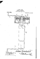
In the accompanying drawing the preferred form of the invention has been shown. Said drawing is a view partly in section and partly in elevation of a complete apparatus embodying the present improvements, the roller and one of the fixtures being shown in elevation, while the controlling fixture is shown in section.
Referring to the figures by characters of reference A designates a shade roller that can be formed of any suitable material and which is provided at each end with trunnions 1 and 2 respectively, the trunnion 1 being cylindrical throughout its length and bearing within a bracket 3 of ordinary construction. The other trunnion 2 however has a flat end portion at designed to project into a correspondingly shaped socket 5 formed in one end of a spindle 21. This spindle is mounted to rotate within an opening formed centrally within a cap 7 closed by means of a detachable base plate 8 to which an angular arm 9 is secured, said arm designed to be attached to a supporting structure in any preferred manner. A socket 10 is formed within the middle portion of the inner surface of this base plate 8 and constitutes a bearing for one end of the spindle 21.
An intermediate plate 17 is provided in the cap 7 and has a central tubular extension 18 provided with one or more notches 19 in its outer surface. A disk 20 is secured to the spindle 21 and has an annular flange 22 surrounding one or more pawls 23 which are pivotally connected to the disk 20. A spring 24 is coiled around the spindle 21, and one end of this spring is secured to the spindle in any suitable manner while the other end thereof is attached to the marginal portion of the intermediate plate 17. lVhen the spindle 21 is rotated so as to wind the spring 2 1 the pawls 23 will move therewith and pass over the notches 19. \Vhen the rotation of the spindle 21 is reversed and said spindle caused to rotate rapidly the pawls 23 will swing outwardly by centrifugal force, so as to pass over the notches 19 without becoming seated therein.
Various changes may be made in the construction and arrangement of the parts without departing from the spirit or sacrificing any of the advantages of the invention.
Vhat is claimed is A fixture for rollers comprising a nonrotatable housing, an intermediate member within the housing having a tubular extension provided with notches, a spindle mounted for rotation within the housing and intermediate member, a spring secured at its ends to the spindle and intermediate member respectively and disposed to be wound upon the spindle when said spindle is rotated in one direction, a disk secured to the spindle, and pawls pivotally connected to the disk, one of said pawls overhanging and normally engaging one of the notches in the tubular extension, said pawls being shiftable by centrifugal force out of engagement with the notched extension.
In testimony that I claim the foregoing as my own, I have hereto affixed my signature in the presence of two witnesses.
NATHAN FLEISCHAKER. lVitnesses:
C. S. VVALDEN, S. A. FRIEDHEIM.
Priority Applications (1)
| Application Number | Priority Date | Filing Date | Title |
|---|---|---|---|
| US45312708A US939994A (en) | 1908-09-15 | 1908-09-15 | Shade-roller fixture. |
Applications Claiming Priority (1)
| Application Number | Priority Date | Filing Date | Title |
|---|---|---|---|
| US45312708A US939994A (en) | 1908-09-15 | 1908-09-15 | Shade-roller fixture. |
Publications (1)
| Publication Number | Publication Date |
|---|---|
| US939994A true US939994A (en) | 1909-11-16 |
Family
ID=3008412
Family Applications (1)
| Application Number | Title | Priority Date | Filing Date |
|---|---|---|---|
| US45312708A Expired - Lifetime US939994A (en) | 1908-09-15 | 1908-09-15 | Shade-roller fixture. |
Country Status (1)
| Country | Link |
|---|---|
| US (1) | US939994A (en) |
-
1908
- 1908-09-15 US US45312708A patent/US939994A/en not_active Expired - Lifetime
Similar Documents
| Publication | Publication Date | Title |
|---|---|---|
| US518967A (en) | Exercising-machine | |
| US348805A (en) | Tape-measure | |
| US873460A (en) | Fan. | |
| US530079A (en) | Curtain-fixture | |
| US778660A (en) | Spring-roller. | |
| US76328A (en) | Improvement in fkiction-clutch | |
| US984044A (en) | Kaleidoscopic top. | |
| US934605A (en) | Awning. | |
| US1062437A (en) | Hinge. | |
| US1261753A (en) | Fan. | |
| US1056673A (en) | Curtain-roller. | |
| US324135A (en) | Petee e | |
| US1277965A (en) | Spring shade-roller. | |
| US473990A (en) | Window-curtain roller | |
| US915111A (en) | Shade-winder. | |
| US149608A (en) | Improvement in curtain-fixtures | |
| US994292A (en) | Portable-electric-light fixture. | |
| US765671A (en) | Mechanical eraser. | |
| US211673A (en) | Improvement in curtain roller and bracket | |
| US705594A (en) | Shade-roller and fixture. | |
| US346098A (en) | Suspension device for lamps | |
| US324709A (en) | Geoege lieb | |
| US866200A (en) | Shade-roller. | |
| US515972A (en) | Suspension fly-fan | |
| US1017714A (en) | Door-closer. |