US939989A - Process for obtaining intimate mixtures. - Google Patents
Process for obtaining intimate mixtures. Download PDFInfo
- Publication number
- US939989A US939989A US40236107A US1907402361A US939989A US 939989 A US939989 A US 939989A US 40236107 A US40236107 A US 40236107A US 1907402361 A US1907402361 A US 1907402361A US 939989 A US939989 A US 939989A
- Authority
- US
- United States
- Prior art keywords
- receptacle
- substances
- masses
- compartments
- mixed
- Prior art date
- Legal status (The legal status is an assumption and is not a legal conclusion. Google has not performed a legal analysis and makes no representation as to the accuracy of the status listed.)
- Expired - Lifetime
Links
- 238000000034 method Methods 0.000 title description 24
- 239000011872 intimate mixture Substances 0.000 title description 6
- 239000000126 substance Substances 0.000 description 26
- 239000000463 material Substances 0.000 description 17
- 239000000203 mixture Substances 0.000 description 12
- 238000002156 mixing Methods 0.000 description 11
- 238000000151 deposition Methods 0.000 description 5
- 230000033001 locomotion Effects 0.000 description 3
- 239000004615 ingredient Substances 0.000 description 2
- OKTJSMMVPCPJKN-UHFFFAOYSA-N Carbon Chemical compound [C] OKTJSMMVPCPJKN-UHFFFAOYSA-N 0.000 description 1
- HCHKCACWOHOZIP-UHFFFAOYSA-N Zinc Chemical compound [Zn] HCHKCACWOHOZIP-UHFFFAOYSA-N 0.000 description 1
- 230000004075 alteration Effects 0.000 description 1
- 229910052799 carbon Inorganic materials 0.000 description 1
- 238000007599 discharging Methods 0.000 description 1
- 239000011701 zinc Substances 0.000 description 1
- 229910052725 zinc Inorganic materials 0.000 description 1
Images

Classifications
-
- B—PERFORMING OPERATIONS; TRANSPORTING
- B01—PHYSICAL OR CHEMICAL PROCESSES OR APPARATUS IN GENERAL
- B01F—MIXING, e.g. DISSOLVING, EMULSIFYING OR DISPERSING
- B01F23/00—Mixing according to the phases to be mixed, e.g. dispersing or emulsifying
- B01F23/50—Mixing liquids with solids
- B01F23/56—Mixing liquids with solids by introducing solids in liquids, e.g. dispersing or dissolving
Definitions
- the present invention relates to a process of mixing granular substances and has for its object to provide a method or process by which the use of apparatus known as dosers will be avoided.
- apparatus known as dosers
- Such apparatus requires a special and very accurate adjustment whenever a substantially different character of mixture is to be obtained and the proper regulation or control and adjustment of such apparatus requires considerable skill.
- dosers it is necessary to have a special apparatus for each of the substances to be included in the mixture and therefore it is not practicable to employ such an apparatus when a number of substances are to be mixed.
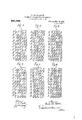
- Figures l to 6 are diagrammatic views; Fig. 7 is a front view of an apparatus adapted to carry out the improved process; Fig. 8 is a side view ofthe apparatus; and Fig. 9 is a horizontal sectional view on the line A-B of Fig.
- vthe process consists in-l, introducing the substances to be mixed into a receptacle which is divided into a plurality of vertical compartments: 2, transferring the lower layer or portion of the contents of each of said vertical compartments to the compartments of a second similar receptacle, in succession: 3, transferring the lower layer or portion of the contents of each ofthe compartments of the second receptacle to the compartments of the first receptacle in succession and 4, repeating such transferring operation as often as may be necessary to obtain the desired mixture. It can be readily demonstrated that by such successive mixing there may be obtained a perfect mixture. That is, a mixture so intimate that any portion thereof will contain the desired proportion of each of the substances or ingredients constituting the mixture.
- Figs. l, 2 and 3 for purposes of illustration, in which are represented two receptacles, designated l, 2, respectively, each divided into five vertical compartments, and assuming that four different substances designated a, l), c and d are to be mixed, it will be seen that such substances are introduced into the compartments of the receptacle l successively.
- the substances may be considered as forming ten horizontal layers each-including a portion of the substances in each vertical compartment and said horizontal layers being indicated by transverse lines on the drawing.
- the several horizontal layers will be of four different classes or characters represented by the reference letters A, B, C and D and each of said layers will have a proportion of each of the substances to be mixed and may be graphically represented as follows B 20,4- b -l- 2c C kl-M9@ V 5 D s a, 2b c d
- the horizontal layers contained in the receptacle l will be successively withdrawn therefrom and conveyed to the vertical compartments of the receptacle 2 which corresponds-.as regards size and relationfof its several compartments to the receptacle l, the several layers being thereby grouped or arranged as indicated in Fig. 2.
- each of the horizontal layers within the receptacle 2 will be of one or the other of two classes represented by the reference letters A, 13 plie contents of which is represented as folows:
- rI ⁇ he partially mixed materials are then withdrawn from the receptacle 2 and transferred to the receptacle 1 in the manner previously described, thereby obtaining a further mixing as represented in Fig. 3.
- the several substances become more intimately mixed and by repeating such operation a proper number of times it is possible to obtain a practically perfect mixture.
- the several substances may be more intimately mixed by varying the order in which they are supplied to the first receptacle 1 so as to obtain in said receptacle for example, ten horizontal layers each different from all of the others instead of but four different layers as represented in Fig. 1.
- receptacles employe-d may be of any desired size and divided into any suitable number of compartments, the size and division of such receptacles depending upon the character of substances to be mixed.
- rIhe apparatus illustrated in Figs. 7, S and 9 includes two similar receptacles1,2, each interiorly divided into a plurality of vertical compartments open atboth ends.
- a horizontal screw conveyer 3 of such length as to extend entirely across both receptacles, said conveyer working within a suitable casing 4, open at its-top, and being adapted, by suitable clutch devices not shown, to rotate in either direction.
- the section of the conveyer 8 cooperating with the belt 5 is the reverse of the section thereof below the belt 6 so that material delivered to said screw by either of the belt conveyers will be carried to an elevator7 arranged between the receptacles 1, 2.
- the elevator 7 is provided at its upper' end with a discharge chute 17 which extends across the top of the casing of the feed screw 3, and a valve 9.1no'unted to turn about an axis 16 is arranged in said chute. By adjusting this valve the elevator can be caused to discharge either into the casing 4 of the feed screw 3 or through the chute 17.
- the manner of using the apparatus may be briefly stated as follows: llhe materials to be mixed are successively delivered to the lower leg of the elevator 7 or to the conveyer 8 and the valve 9 is adjusted into position to extend across the discharge chute. Power being supplied to the elevator and feed screw 3, and the latter rotated to convey material through the casing 4 over the receptacle 1, the compartments 11, 12, 13, 14 and 15 of said receptacle will be successively filled. Vlhen the receptacle 1 is completely filled or the desired amount of material deposited there in, the supply of material is cut off; and thereafter the conveyers 5 and 8 are started and the direction of movement of the feeding screw 3 reversed.
- the conveyer 5 op erates to remove the material from the receptacle 1, each of the compartments in said receptacle simultaneously discharging upon the conveyer and thereby the several substances previously contained in said receptacle will be primarily mixed as they are delivered to the screw conveyer 8.
- the partially mixed materials will be discharged into the casing 4 and by the feed screw 3 deposited in the receptacle 2, the compartments 21, 22, 23, 24 and 25 of said receptacle being suc- 105 cessively filled.
- the belt conveyer 6 is set in motion the materials contained in the receptacle 2 will be withdrawn and if a further mixing is not desired the valve 9 will be adjusted to cause the elevator to dis- 110 charge through the chute 17.
- the materials contained in the receptacle 2 will be withdrawn and if a further mixing is not desired the valve 9 will be adjusted to cause the elevator to dis- 110 charge through the chute 17.
- the valve 9 will be adjusted to cause the elevator to dis- 110 charge through the chute 17.
- valve 9 is left in position to cause the elevator to discharge its load on to the feed screw 3, and the direct-ion of movement of said screw is again reversed, the materials 115 which have been mixed by the action of the conveyers 5 and 6 will be returned to the receptacle 1 and again mixed as they are withdrawn from such receptacle by the conveyer 5.
Landscapes
- Chemical & Material Sciences (AREA)
- Dispersion Chemistry (AREA)
- Chemical Kinetics & Catalysis (AREA)
- Accessories For Mixers (AREA)
Description
E. DOR-DELATTRE. PROCESS POR OBTAINING IN TIMATB MIXTURES.
APPLIOATION FILED NOV. 15, 1907.
JQJHC j C-d5 dcee d 'accac E. D(LR-DELA'II'RE.` PROCESS PoR OBTAINING INTIMATB MIXTURBS.
APPLICATION FILED NOV. l5, 1907.
Patented Nov. 16. 1909.
2 SHEETS-SHEET 2.
//r, f iv atromeia Wwf EMILE DOR-DELATTRE, 0F LIEGE, BELGIUM.
PROCESS FOR OBTAINING- INTIMATE MIXTURES.
Specication of Letters Patent.
Patented Nov. 16, 1909.
Application led November 15, 1907. Serial No. 402,361.
To all whom it 'may concern:
Be it known that I, EMILE BoR-DnLA'r'rRn, a resident of Liege, Belgium, a subject of the King of the Belgians, engineer, have invented certain new and useful Improvements in Processes for Obtaining Intimate Mixtures, of which the following is a full, clear, and exact description, such as will enable others skilled in the art to which it appertains to make and use the same.
The present invention relates to a process of mixing granular substances and has for its object to provide a method or process by which the use of apparatus known as dosers will be avoided. Such apparatus requires a special and very accurate adjustment whenever a substantially different character of mixture is to be obtained and the proper regulation or control and adjustment of such apparatus requires considerable skill. Also in using dosers it is necessary to have a special apparatus for each of the substances to be included in the mixture and therefore it is not practicable to employ such an apparatus when a number of substances are to be mixed.
By the process forming the subject of the present invention it is possible not only to obtain a very intimate mixture of any number of different substances, but also avoid the necessity of making any alteration or varying the operation of any part when the character of substances or material to be treated is varied.
While the process herein described is adapted to be employed in various arts and for mixing various substances, it has been employed in mixing zinc ore with carbon preliminary to reducing such ore. From the' description of the process hereinafter presented it will be evident, however, that its use is not limited to any one art or any particular substance or substances, but it may be employed wherever it is desired to obtain an intimate mixture of any substances adapted to be handled in the manner described.
In the accompanying drawings: Figures l to 6 are diagrammatic views; Fig. 7 is a front view of an apparatus adapted to carry out the improved process; Fig. 8 is a side view ofthe apparatus; and Fig. 9 is a horizontal sectional view on the line A-B of Fig. 7 Y Referring particularly to the diagrammatic views it will be seen that, briefly stated,vthe process consists in-l, introducing the substances to be mixed into a receptacle which is divided into a plurality of vertical compartments: 2, transferring the lower layer or portion of the contents of each of said vertical compartments to the compartments of a second similar receptacle, in succession: 3, transferring the lower layer or portion of the contents of each ofthe compartments of the second receptacle to the compartments of the first receptacle in succession and 4, repeating such transferring operation as often as may be necessary to obtain the desired mixture. It can be readily demonstrated that by such successive mixing there may be obtained a perfect mixture. That is, a mixture so intimate that any portion thereof will contain the desired proportion of each of the substances or ingredients constituting the mixture.
Referring to Figs. l, 2 and 3, for purposes of illustration, in which are represented two receptacles, designated l, 2, respectively, each divided into five vertical compartments, and assuming that four different substances designated a, l), c and d are to be mixed, it will be seen that such substances are introduced into the compartments of the receptacle l successively. The substances may be considered as forming ten horizontal layers each-including a portion of the substances in each vertical compartment and said horizontal layers being indicated by transverse lines on the drawing. As shown, the several horizontal layers will be of four different classes or characters represented by the reference letters A, B, C and D and each of said layers will have a proportion of each of the substances to be mixed and may be graphically represented as follows B 20,4- b -l- 2c C kl-M9@ V 5 D s a, 2b c d In carrying out the process the horizontal layers contained in the receptacle l will be successively withdrawn therefrom and conveyed to the vertical compartments of the receptacle 2 which corresponds-.as regards size and relationfof its several compartments to the receptacle l, the several layers being thereby grouped or arranged as indicated in Fig. 2. By these two mixings each of the horizontal layers within the receptacle 2 will be of one or the other of two classes represented by the reference letters A, 13 plie contents of which is represented as folows:
rI`he partially mixed materials are then withdrawn from the receptacle 2 and transferred to the receptacle 1 in the manner previously described, thereby obtaining a further mixing as represented in Fig. 3. At every repetition of the step of withdrawing substances from one receptacle and transferring the same to another, the several substances become more intimately mixed and by repeating such operation a proper number of times it is possible to obtain a practically perfect mixture.
As represented in Figs. 4, 5 and 6 the several substances may be more intimately mixed by varying the order in which they are supplied to the first receptacle 1 so as to obtain in said receptacle for example, ten horizontal layers each different from all of the others instead of but four different layers as represented in Fig. 1.
Of course the receptacles employe-d may be of any desired size and divided into any suitable number of compartments, the size and division of such receptacles depending upon the character of substances to be mixed.
The process is adapted to be carried out by various forms of apparatus t-he one illustrated being that forming the subject of Patent No. 922,863, the application for which was iiled of even date herewith, and it will be seen that by it and after a relatively small number of transferring operations a very intimate mixture of any number of ingredients may be obtained.
rIhe apparatus illustrated in Figs. 7, S and 9 includes two similar receptacles1,2, each interiorly divided into a plurality of vertical compartments open atboth ends. Above the receptacles is arranged a horizontal screw conveyer 3 of such length as to extend entirely across both receptacles, said conveyer working within a suitable casing 4, open at its-top, and being adapted, by suitable clutch devices not shown, to rotate in either direction. Below each receptacle is arranged a belt conveyer 5, 6, adapted to deliver material received thereon to a screw conveyer 8. The section of the conveyer 8 cooperating with the belt 5 is the reverse of the section thereof below the belt 6 so that material delivered to said screw by either of the belt conveyers will be carried to an elevator7 arranged between the receptacles 1, 2. The elevator 7 is provided at its upper' end with a discharge chute 17 which extends across the top of the casing of the feed screw 3, and a valve 9.1no'unted to turn about an axis 16 is arranged in said chute. By adjusting this valve the elevator can be caused to discharge either into the casing 4 of the feed screw 3 or through the chute 17. The manner of using the apparatus may be briefly stated as follows: llhe materials to be mixed are successively delivered to the lower leg of the elevator 7 or to the conveyer 8 and the valve 9 is adjusted into position to extend across the discharge chute. Power being supplied to the elevator and feed screw 3, and the latter rotated to convey material through the casing 4 over the receptacle 1, the compartments 11, 12, 13, 14 and 15 of said receptacle will be successively filled. Vlhen the receptacle 1 is completely filled or the desired amount of material deposited there in, the supply of material is cut off; and thereafter the conveyers 5 and 8 are started and the direction of movement of the feeding screw 3 reversed. The conveyer 5 op erates to remove the material from the receptacle 1, each of the compartments in said receptacle simultaneously discharging upon the conveyer and thereby the several substances previously contained in said receptacle will be primarily mixed as they are delivered to the screw conveyer 8. By this conveyer and the elevator 7 the partially mixed materials will be discharged into the casing 4 and by the feed screw 3 deposited in the receptacle 2, the compartments 21, 22, 23, 24 and 25 of said receptacle being suc- 105 cessively filled. When the belt conveyer 6 is set in motion the materials contained in the receptacle 2 will be withdrawn and if a further mixing is not desired the valve 9 will be adjusted to cause the elevator to dis- 110 charge through the chute 17. However, if
the valve 9 is left in position to cause the elevator to discharge its load on to the feed screw 3, and the direct-ion of movement of said screw is again reversed, the materials 115 which have been mixed by the action of the conveyers 5 and 6 will be returned to the receptacle 1 and again mixed as they are withdrawn from such receptacle by the conveyer 5.
Having thus described the invention what is claimed is:
1. The herein described method or process of mixing granular substances consisting in depositing the material in a plurality of 125 masses, withdrawing portions of each of said masses and forming therefrom another mass separate from those aforesaid, continuing this operation to form a plurality of such secondary masses, treating said' Second- 130 ary masses in a similar manner to form a third set of masses each containing portions of all of said secondary masses and continuing such procedure until the desired mixture is obtained.
2. The herein described method or process of mixing granular substances consisting in depositing` the material in a plurality of masses, simultaneously withdrawing material from the bottom of each of said masses and depositing the same successively in a plurality of secondary masses each independent of those aforesaid, and by similar operations forming as many subsequent series of masses as are necessary to produce the desired mixture.
3. The herein described method or process of mixing granular substances consisting in depositing the material in a plurality of masses, withdrawing horizontal layers ofv material from all of said masses and depositing the same vertically 1n masses independent of those aforesaid, and similarly treating the second and subsequent series of masses until the desired mixture is obtained.
4e. The herein described method or process of mixing granular substances, consisting in depositing the substances to be mixed in a. plurality of independent vertical masses, simultaneously withdrawing the lowermost portion of the content-s of each of said masses and transferring the same to the first of a plurality of independent masses similar to those aforesaid, continuing this step and forming said secondary masses successively until all of the first said series of masses is thus shifted, and, by similar operations, forming subsequent series of masses until the desired mixture is obtained.
In testimony whereof I have signed my name to this specification in the presence of two subscribing witnesses.
EMILE DOR-DELATTRE. `Witnesses A. PICARD, ED. SEPULGHRE.
Priority Applications (1)
| Application Number | Priority Date | Filing Date | Title |
|---|---|---|---|
| US40236107A US939989A (en) | 1907-11-15 | 1907-11-15 | Process for obtaining intimate mixtures. |
Applications Claiming Priority (1)
| Application Number | Priority Date | Filing Date | Title |
|---|---|---|---|
| US40236107A US939989A (en) | 1907-11-15 | 1907-11-15 | Process for obtaining intimate mixtures. |
Publications (1)
| Publication Number | Publication Date |
|---|---|
| US939989A true US939989A (en) | 1909-11-16 |
Family
ID=3008407
Family Applications (1)
| Application Number | Title | Priority Date | Filing Date |
|---|---|---|---|
| US40236107A Expired - Lifetime US939989A (en) | 1907-11-15 | 1907-11-15 | Process for obtaining intimate mixtures. |
Country Status (1)
| Country | Link |
|---|---|
| US (1) | US939989A (en) |
Cited By (1)
| Publication number | Priority date | Publication date | Assignee | Title |
|---|---|---|---|---|
| US2593425A (en) * | 1947-03-14 | 1952-04-22 | Houdry Process Corp | Classifying system for pieces of solid material having unequal size |
-
1907
- 1907-11-15 US US40236107A patent/US939989A/en not_active Expired - Lifetime
Cited By (1)
| Publication number | Priority date | Publication date | Assignee | Title |
|---|---|---|---|---|
| US2593425A (en) * | 1947-03-14 | 1952-04-22 | Houdry Process Corp | Classifying system for pieces of solid material having unequal size |
Similar Documents
| Publication | Publication Date | Title |
|---|---|---|
| US4375335A (en) | Silo combination for mixing stored material | |
| US722782A (en) | Apparatus for making concrete. | |
| US1663173A (en) | Process of and apparatus for controlling the movement of masses of solids of various sizes | |
| DE2838110A1 (en) | Quality control system for thermoplastics extruder - where ingredients have individual feed screws regulated from sensors at extruder nozzle | |
| FI57702B (en) | FREQUENCY REQUIREMENTS FOR CONTAINER CONSTRUCTION REQUIREMENTS FOR PULL FORMULATION ELLER STYCKEFORMIGT MATERIAL FRAON EN BEHAOLLARE | |
| US1215739A (en) | Feeding mechanism. | |
| US1185118A (en) | Method of mixing and transporting concrete. | |
| US1726812A (en) | Proportioning apparatus | |
| US993294A (en) | Device for feeding pulverulent material. | |
| US633313A (en) | Apparatus for making concrete. | |
| US677677A (en) | Process of storing and averaging materials in bulk. | |
| US1621307A (en) | Grain mixer | |
| US1369248A (en) | Apparatus for mixing granular substances | |
| US1346828A (en) | Apparatus for mixing cotton | |
| US660845A (en) | Apparatus for sampling, averaging, mixing, and storing materials in bulk. | |
| US662063A (en) | Process of sampling, averaging, mixing, and storing materials in bulk. | |
| US1116182A (en) | Mixing apparatus. | |
| US1204163A (en) | Powder-blending machine. | |
| US3860129A (en) | Apparatus for homogenizing particulate material | |
| US533488A (en) | Machine for manufacturing artificial fuel | |
| US1096103A (en) | Method and apparatus for mixing concrete. | |
| US1328486A (en) | Mixing apparatus for granular, powdered, or the like material | |
| US1260983A (en) | Method of curing starch. | |
| US1167883A (en) | Method of charging blast-furnaces. | |
| US1988531A (en) | Hopper, chute, and the like for feeding lumpy, granular, or pulverulent material |