US939923A - Governor for internal-combustion engines. - Google Patents
Governor for internal-combustion engines. Download PDFInfo
- Publication number
- US939923A US939923A US25574805A US1905255748A US939923A US 939923 A US939923 A US 939923A US 25574805 A US25574805 A US 25574805A US 1905255748 A US1905255748 A US 1905255748A US 939923 A US939923 A US 939923A
- Authority
- US
- United States
- Prior art keywords
- valve
- casing
- governor
- pipe
- pump
- Prior art date
- Legal status (The legal status is an assumption and is not a legal conclusion. Google has not performed a legal analysis and makes no representation as to the accuracy of the status listed.)
- Expired - Lifetime
Links
- 238000002485 combustion reaction Methods 0.000 title description 8
- XLYOFNOQVPJJNP-UHFFFAOYSA-N water Substances O XLYOFNOQVPJJNP-UHFFFAOYSA-N 0.000 description 14
- 239000000203 mixture Substances 0.000 description 5
- 241000218737 Mycobacterium phage Power Species 0.000 description 4
- 210000002445 nipple Anatomy 0.000 description 3
- 238000010276 construction Methods 0.000 description 1
- 230000008878 coupling Effects 0.000 description 1
- 238000010168 coupling process Methods 0.000 description 1
- 238000005859 coupling reaction Methods 0.000 description 1
- 210000005069 ears Anatomy 0.000 description 1
- 238000004519 manufacturing process Methods 0.000 description 1
- 230000000717 retained effect Effects 0.000 description 1
Images

Classifications
-
- F—MECHANICAL ENGINEERING; LIGHTING; HEATING; WEAPONS; BLASTING
- F02—COMBUSTION ENGINES; HOT-GAS OR COMBUSTION-PRODUCT ENGINE PLANTS
- F02D—CONTROLLING COMBUSTION ENGINES
- F02D9/00—Controlling engines by throttling air or fuel-and-air induction conduits or exhaust conduits
Definitions
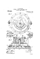
- Figure 1 is a view partly in section of an internal combustion engine, showing one embodiment of my invention applied thereto.
- Fig. 2 is a view partly in plan and partly in section of the governor proper.
- Fig. 3 is a sectional view taken on the lines 3-3 of Fig. v2.
- Fig. 4 is a longitudinal section of the governor valve the view beingtaken on the lines H of Fig. 5, and
- Fig. 5 is a vertical section thereof taken on the lines -5 of Fig. 4.
- I provide a means for keeping the speed of the motor constant or varying it at will by controlling the inlet of the mixture. This is controlled by a throttle valve,.t he position of which is varied and determined by the flow of the circulating water.
- the flow of Water will be determined by the speed of the engine, and will vary with such speed, being due to a pump operated by the motor.
- the speed of the motor may be controlled within limits by varying the pressure of water acting upon thethrottle valve.
- FIG. 1 represents a motor of the internal combustion type. As shown this motor has a single cylinder, but it is to be understood that the character of the moas necessary or desirable.
- the motor is provided with a water jacket indicated at 2.
- a pump?) is driven in time with the engine, conventional mechanism being shown consisting of gear wheels 4, 5, on the pump shaft and engine shaft respectively for attaining this object.
- the pump may be a rotary or reciprocating pump whichever is preferred in practice as the character of the pump does not affect the invention.
- the circulating system comof the casing 13 is inserted I prises a pipe 6 leading from the pump to the water jacket and a pipe 7 leading from the water jacket to a tank 8.
- a pipe 9. leading from the tank to the pump completes the circulating system.
- a carbureter l0 connecting through an inlet pipe 11 to the engine.
- the parts described are those commonly employed in'commercial use.
- the governor comprises a casing 13 secured to a base 14, by bolts 15. At the base of the casing 13 is a chamber 16. W ithin this chamber is a diaphragm 17. The draphragm may be conveniently retained. 1n place by being clamped between the casing 13 and the base 14 by means of bolts 15.
- the base '14 contains a passage '18 extending throughout its length, the portions of the base adjacent to the ends of the passages being extended to form nipples or couplings 19, to which pipes may be secured.
- a branch passage extends between the chamber 16 and the passage 18 below the diaphragm 17.
- a second casing 21 within the upper portion a second casing 21.
- This casing may have a flange through which securing bolts 23 may pass, for attaching it to the casing 13.
- the casing 21 is smaller than the casing 13 so that an annular passage 24 is provided between the two.
- This passage 24 communicates with the outside through an extension passage 25 formed in the casing 13.
- Thisportion of the casing may be prov ded with a flange 26 for attachment to a pipe forming the exit of the carbureter 10.
- the upper portion of the casing 21 is contractedytornxing an exit pipe 27, and the ends of this pipe may be provided with ears 28 for attachment to the pipe 11 connected to the engine.
- a throttle valve 29 Within the casing 21 is mounted a throttle valve 29.
- This valve is cup shaped as shown, and is provided with a central hollow boss 30' for attachment to the hft ng stem 31.
- This stem passes through an open ing formed in the casing 13 and 111 order to form an elongated bearing for the stem a hollow support 32 is formed upon the cas ng 13.
- the throttle valve is provided with ports 33 which when the valve is seated will register with ports 34 formed in the inner casing :21. Additional ports 35 may be formed in this casing above the upper edge of the valve, such ports being adapted to be closed by the raising of the valve'.
- a spring 36 within the chamber 21 is used for seating the valve.
- Small ports 37 formed in the bottom of the valve permit an equalization of pressure below the valve 'so that a vacuum will not be formed when the valve is lifted.
- Other ports'38 formed in the casing 13 connect the upper part of the diaphragm chamber 16 with the external air, so that pressure willbe equalized.
- the governor is located between the carbureter 10 and the entrance pipe 11 of the engine as already described, the carbureter being connected to the inlet pipe 25 and the pipe 11 to the outlet pipe 27.
- the valve 29 is shown in Fig.3 in the open position.
- ports 34 and 35 are of suflicient area to permit the mixture to pass through the apparatus in the desired amount; the valve being water being varied opened or closed will vary the amount of mixturefiowing from the carbureter to the engine as will be obvious.
- a pipe 39 is connected to the-pipe 6 the pipe 39 being of considerably smaller capacity than the pipe 6 so that only a small portion of water flowing from the pump will be diverted or shuntwater to the passa ed to one side, and passed through this pipe.
- the pipe 39 connects with the four way cook 'ment to the pipes 39, 41, 42, 43, respectively,
- a valveastemjl having a squared extremity 52, for attachment of an operating lever 53 (see Fig. 1.)
- the stem isprovided with ports 55, 56, in line with the passages 49, 50, respectively. These ports are arranged at an angle of 45 to each other as shown in Fig. 5.
- the pressure of the water within the diaphragm chamber will vary according to the speed of the pump, and motor,- and with the extent of opening of the four way cock.
- the cock being set for a definite amount of opening, the amount of water passing through it will depend upon the speed of the pump and the pressure of the spring in the throttle valve,'these two forces being correlative.
- the speed of the pump increases the pressure rises, and the valve is closed reducing the amount of mixture admitted to the engine.
- the pressure is reduced and the valve is opened, thus admitting more mixture.
- a overnor for ex losive en ines the .combination with a casing, a diaphragm chamber therein, a base having a water passage, nipples communicating with the ends 1 of ⁇ the water passage, a diaphragm clamped between the casing and the base and within the diaphragm chamber, a valve casing within the casing, the said valve-casing having a flange secured to the casing, a throttle valve within the valve-casing, ports formed within the valve and valve-casing, a stem on the valve extending into the diaphragm chamber, and engaging with the diaphragm,
- governor arranged between the carbureter the inlet thereto is opened, and by means of 10 and the inlet valve of the engine, the said 1 which the pressure Within the regulator may goiernor including a throttle valve for the be controlled.
Landscapes
- Engineering & Computer Science (AREA)
- Chemical & Material Sciences (AREA)
- Combustion & Propulsion (AREA)
- Mechanical Engineering (AREA)
- General Engineering & Computer Science (AREA)
- Fire-Extinguishing By Fire Departments, And Fire-Extinguishing Equipment And Control Thereof (AREA)
Description
W. M. POWER. GOVERNOR FOR INTERNAL COMBUSTION ENGINES.
APPLICATION FILED APR. 15, 1905.
Patented Nov. 9, 1909.
2 SHEETSSHEET 1.
Inventor Attorneys.
W. M. POWER. GOVERNOR FOR INTERNAL COMBUSTION ENGINES. APPLICATION FILED APR. 15, 1905.
939,923. I Patented Nov. 9, 1909.
2 SHEETSSHBET Z.
7 i g 4 Q g f 3 45 aunt! 1 5 m.
'37 33 J5, J0) J6 /7 52 31 J9 W s fi Witnesses: X Inventor Attorneys.
New York,
WILLIAM M. POWER, OF PORTCHES'TER, NEW YORK.
GO VERNOR FOR INTERNAL--COMIBUSTION ENGINES.
Specification of Letters Patent.
Patented Nov. 9, 1909.
Application filed April 15, 1905. Serial No. 255,748.
To all whom it may concern."
Be it known that I, WVILLIAM M. POWER, a citizen of the United States, residing in Portchester, county of VVestchester, State of have invented a certain new and useful Improvement in Governors for Internal-Combustion Engines, of which the following is a specification.
The object I have in view is the production of a governor, for controlling the speed of internal combustion engines which are subject to varying load, and for varying the tor may be varied speed at will. I attain these objects by the mechanism illustrated in the accompanying drawings, in which,
Figure 1 is a view partly in section of an internal combustion engine, showing one embodiment of my invention applied thereto. Fig. 2 is a view partly in plan and partly in section of the governor proper. Fig. 3 is a sectional view taken on the lines 3-3 of Fig. v2. Fig. 4 is a longitudinal section of the governor valve the view beingtaken on the lines H of Fig. 5, and Fig. 5 is a vertical section thereof taken on the lines -5 of Fig. 4.
In all the views like parts are designated by the same reference characters.
In carrying out my invention I provide a means for keeping the speed of the motor constant or varying it at will by controlling the inlet of the mixture. This is controlled by a throttle valve,.t he position of which is varied and determined by the flow of the circulating water. The flow of Water will be determined by the speed of the engine, and will vary with such speed, being due to a pump operated by the motor. The speed of the motor may be controlled within limits by varying the pressure of water acting upon thethrottle valve.
In the drawings 1 represents a motor of the internal combustion type. As shown this motor has a single cylinder, but it is to be understood that the character of the moas necessary or desirable. The motor is provided with a water jacket indicated at 2. A pump?) is driven in time with the engine, conventional mechanism being shown consisting of gear wheels 4, 5, on the pump shaft and engine shaft respectively for attaining this object. The pump may be a rotary or reciprocating pump whichever is preferred in practice as the character of the pump does not affect the invention. The circulating system comof the casing 13 is inserted I prises a pipe 6 leading from the pump to the water jacket and a pipe 7 leading from the water jacket to a tank 8. A pipe 9. leading from the tank to the pump completes the circulating system. In connection with the engine thus described is employed a carbureter l0 connecting through an inlet pipe 11 to the engine. The parts described are those commonly employed in'commercial use.
In connection with the mechanism already described I employ a governor indicated in Fig. l by the numeral 12. The details of the I governor are illustrated in the other views. The governor comprises a casing 13 secured to a base 14, by bolts 15. At the base of the casing 13 is a chamber 16. W ithin this chamber is a diaphragm 17. The draphragm may be conveniently retained. 1n place by being clamped between the casing 13 and the base 14 by means of bolts 15. The base '14 contains a passage '18 extending throughout its length, the portions of the base adjacent to the ends of the passages being extended to form nipples or couplings 19, to which pipes may be secured. A branch passage extends between the chamber 16 and the passage 18 below the diaphragm 17. Within the upper portion a second casing 21. This casing may have a flange through which securing bolts 23 may pass, for attaching it to the casing 13. The casing 21 is smaller than the casing 13 so that an annular passage 24 is provided between the two. This passage 24 communicates with the outside through an extension passage 25 formed in the casing 13. Thisportion of the casing may be prov ded with a flange 26 for attachment to a pipe forming the exit of the carbureter 10. The upper portion of the casing 21 is contractedytornxing an exit pipe 27, and the ends of this pipe may be provided with ears 28 for attachment to the pipe 11 connected to the engine.
Within the casing 21 is mounted a throttle valve 29. This valve is cup shaped as shown, and is provided with a central hollow boss 30' for attachment to the hft ng stem 31. This stem passes through an open ing formed in the casing 13 and 111 order to form an elongated bearing for the stem a hollow support 32 is formed upon the cas ng 13. The throttle valve is provided with ports 33 which when the valve is seated will register with ports 34 formed in the inner casing :21. Additional ports 35 may be formed in this casing above the upper edge of the valve, such ports being adapted to be closed by the raising of the valve'. A spring 36 within the chamber 21 is used for seating the valve. Small ports 37 formed in the bottom of the valve permit an equalization of pressure below the valve 'so that a vacuum will not be formed when the valve is lifted. Other ports'38 formed in the casing 13 connect the upper part of the diaphragm chamber 16 with the external air, so that pressure willbe equalized.
I The governor is located between the carbureter 10 and the entrance pipe 11 of the engine as already described, the carbureter being connected to the inlet pipe 25 and the pipe 11 to the outlet pipe 27. The valve 29 is shown in Fig.3 in the open position. The
In connection'with the governor already described means is provided for admitting e 18, the pressure of the according to the speed of the motor. In Fig. 1 a pipe 39 is connected to the-pipe 6 the pipe 39 being of considerably smaller capacity than the pipe 6 so that only a small portion of water flowing from the pump will be diverted or shuntwater to the passa ed to one side, and passed through this pipe. The pipe 39 connects with the four way cook 'ment to the pipes 39, 41, 42, 43, respectively,
the nipples 45 and 46 being arranged opposite to each other. Within the body 44 is located a valveastemjl having a squared extremity 52, for attachment of an operating lever 53 (see Fig. 1.) The stem isprovided with ports 55, 56, in line with the passages 49, 50, respectively. These ports are arranged at an angle of 45 to each other as shown in Fig. 5. By this construction the How of Water through the regulator can be varied. By turning the valve so that the passage through the pipes 39 and 41 will be entirely open, the passage through the pipes 42 and 43' will be closed. When in this p0? sition, the maximum amount of pressure will exist within the passage 18 and the diaphragm 17 will be elevated, entirely closing the throttle valve, solong as the pressure is sufiicient to compress the spring 36. By
seams varying the position of the valve 40, the inlet through the pipes 39 and 41 will be gradually closed and the outlet to the pipes 42, and 43 will be gradually opened, thus reliev ing the pressure through the passage 18. The turning of the valve 40 may be continued until the pipes 39 and 41 are entirely closed and the pipes 42 and 43 entirely opened at which time there will be no pressure within the chamber 18. By employing this four way valve very delicate adjustment can be secured, and the motor can be controlled within very close limits.
In operation, the pressure of the water within the diaphragm chamber will vary according to the speed of the pump, and motor,- and with the extent of opening of the four way cock. The cock being set for a definite amount of opening, the amount of water passing through it will depend upon the speed of the pump and the pressure of the spring in the throttle valve,'these two forces being correlative. As the speed of the pump increases the pressure rises, and the valve is closed reducing the amount of mixture admitted to the engine. As the speed of the engine is reduced by such action the pressure is reduced and the valve is opened, thus admitting more mixture.
Having now described my invention, what I claim and desire to secure by Letters Patcut, is
1. In a governor for internal combustion engines, the combination with the circulatindependently of the speed of the engines.
2. In a overnor for ex losive en ines the .combination with a casing, a diaphragm chamber therein, a base having a water passage, nipples communicating with the ends 1 of\ the water passage, a diaphragm clamped between the casing and the base and within the diaphragm chamber, a valve casing within the casing, the said valve-casing having a flange secured to the casing, a throttle valve within the valve-casing, ports formed within the valve and valve-casing, a stem on the valve extending into the diaphragm chamber, and engaging with the diaphragm,
a hollow boss formed on the valve and engaging with the stem, and a gu1de secured to the casing and surroundin thestem.
3. In a governor for exp osive engines, the
combination with the en me of a pump and the circulating system 0 the water acket, a
governor arranged between the carbureter the inlet thereto is opened, and by means of 10 and the inlet valve of the engine, the said 1 which the pressure Within the regulator may goiernor including a throttle valve for the be controlled.
mixture, a spring for opening the valve and This specification signed and witnessed a diaphragm for closing it, and tubular conthis tenth day of April, 1905.
nections between the circulating system and WVILLIAM M. POWER.
the governor, the said connections including a four-Way cock, by means of which the outi Witnesses: I let from the diaphragm may be cut off as l LEONARD H. DYER, J N0. R0131. TAYLOR.
Priority Applications (1)
| Application Number | Priority Date | Filing Date | Title |
|---|---|---|---|
| US25574805A US939923A (en) | 1905-04-15 | 1905-04-15 | Governor for internal-combustion engines. |
Applications Claiming Priority (1)
| Application Number | Priority Date | Filing Date | Title |
|---|---|---|---|
| US25574805A US939923A (en) | 1905-04-15 | 1905-04-15 | Governor for internal-combustion engines. |
Publications (1)
| Publication Number | Publication Date |
|---|---|
| US939923A true US939923A (en) | 1909-11-09 |
Family
ID=3008341
Family Applications (1)
| Application Number | Title | Priority Date | Filing Date |
|---|---|---|---|
| US25574805A Expired - Lifetime US939923A (en) | 1905-04-15 | 1905-04-15 | Governor for internal-combustion engines. |
Country Status (1)
| Country | Link |
|---|---|
| US (1) | US939923A (en) |
-
1905
- 1905-04-15 US US25574805A patent/US939923A/en not_active Expired - Lifetime
Similar Documents
| Publication | Publication Date | Title |
|---|---|---|
| US1191700A (en) | Auxiliary air-valve. | |
| US4854270A (en) | Intake system for internal combustion engines | |
| US2167266A (en) | Valve for automatic control of supplementary liquids | |
| US1310683A (en) | Supercharging device fob turbo-compressors | |
| US1346564A (en) | Supercharging device for turbo-compressors | |
| US1120118A (en) | Auxiliary air-inlet device for internal-combustion engines. | |
| US2415509A (en) | Engine governor | |
| US1232041A (en) | Hydrocarbon-motor. | |
| US2409533A (en) | Apparatus for controlling superchargers | |
| US1272204A (en) | Priming device. | |
| US1244686A (en) | Vacuum system for internal-combustion engines. | |
| US2065909A (en) | Fluid pressure throttle control for engines | |
| US1547695A (en) | Manual control for turbines | |
| US1412487A (en) | Carburetor | |
| US997232A (en) | Carbureter. | |
| US1096962A (en) | Governor. | |
| US1117993A (en) | Automatic valve. | |
| US1346565A (en) | Turbine control-housing | |
| US1297193A (en) | Steam-regulating valve. | |
| US1000398A (en) | Carbureter. | |
| US855065A (en) | Pump-governor. | |
| USRE19331E (en) | Governor | |
| US1169340A (en) | Carbureter. | |
| US891064A (en) | Engine-governor. | |
| US1431224A (en) | geabe |