US9394603B2 - Soft sputtering magnetron system - Google Patents
Soft sputtering magnetron system Download PDFInfo
- Publication number
- US9394603B2 US9394603B2 US13/885,905 US201113885905A US9394603B2 US 9394603 B2 US9394603 B2 US 9394603B2 US 201113885905 A US201113885905 A US 201113885905A US 9394603 B2 US9394603 B2 US 9394603B2
- Authority
- US
- United States
- Prior art keywords
- target
- substrate
- targets
- flux
- distance
- Prior art date
- Legal status (The legal status is an assumption and is not a legal conclusion. Google has not performed a legal analysis and makes no representation as to the accuracy of the status listed.)
- Active, expires
Links
- 238000004544 sputter deposition Methods 0.000 title claims abstract description 41
- 239000000758 substrate Substances 0.000 claims abstract description 124
- 230000004907 flux Effects 0.000 claims abstract description 70
- 230000003628 erosive effect Effects 0.000 claims abstract description 53
- 238000000151 deposition Methods 0.000 claims abstract description 29
- 238000000429 assembly Methods 0.000 claims abstract description 26
- 230000000712 assembly Effects 0.000 claims abstract description 26
- 230000008021 deposition Effects 0.000 claims abstract description 24
- 238000000034 method Methods 0.000 claims description 27
- 239000013077 target material Substances 0.000 claims description 27
- 239000000463 material Substances 0.000 abstract description 7
- 230000009977 dual effect Effects 0.000 abstract description 4
- 238000005477 sputtering target Methods 0.000 abstract description 2
- 239000007789 gas Substances 0.000 description 20
- 239000010408 film Substances 0.000 description 16
- 238000000576 coating method Methods 0.000 description 15
- 239000011248 coating agent Substances 0.000 description 12
- 230000008569 process Effects 0.000 description 11
- 238000009826 distribution Methods 0.000 description 10
- XKRFYHLGVUSROY-UHFFFAOYSA-N Argon Chemical compound [Ar] XKRFYHLGVUSROY-UHFFFAOYSA-N 0.000 description 4
- 239000010409 thin film Substances 0.000 description 4
- 238000010586 diagram Methods 0.000 description 3
- 238000005546 reactive sputtering Methods 0.000 description 3
- IJGRMHOSHXDMSA-UHFFFAOYSA-N Atomic nitrogen Chemical compound N#N IJGRMHOSHXDMSA-UHFFFAOYSA-N 0.000 description 2
- 229910052786 argon Inorganic materials 0.000 description 2
- 230000008901 benefit Effects 0.000 description 2
- 230000015572 biosynthetic process Effects 0.000 description 2
- 150000001875 compounds Chemical class 0.000 description 2
- 239000002826 coolant Substances 0.000 description 2
- 239000003989 dielectric material Substances 0.000 description 2
- 238000001755 magnetron sputter deposition Methods 0.000 description 2
- 230000007246 mechanism Effects 0.000 description 2
- 229910052751 metal Inorganic materials 0.000 description 2
- 239000002184 metal Substances 0.000 description 2
- 239000000203 mixture Substances 0.000 description 2
- 150000004767 nitrides Chemical class 0.000 description 2
- 239000002245 particle Substances 0.000 description 2
- 238000001552 radio frequency sputter deposition Methods 0.000 description 2
- 230000007480 spreading Effects 0.000 description 2
- XLYOFNOQVPJJNP-UHFFFAOYSA-N water Substances O XLYOFNOQVPJJNP-UHFFFAOYSA-N 0.000 description 2
- 239000006096 absorbing agent Substances 0.000 description 1
- QVGXLLKOCUKJST-UHFFFAOYSA-N atomic oxygen Chemical compound [O] QVGXLLKOCUKJST-UHFFFAOYSA-N 0.000 description 1
- 230000002902 bimodal effect Effects 0.000 description 1
- 230000008859 change Effects 0.000 description 1
- 239000004020 conductor Substances 0.000 description 1
- 238000001816 cooling Methods 0.000 description 1
- 239000000498 cooling water Substances 0.000 description 1
- 238000005137 deposition process Methods 0.000 description 1
- 239000011521 glass Substances 0.000 description 1
- 238000009499 grossing Methods 0.000 description 1
- 230000003993 interaction Effects 0.000 description 1
- 230000001788 irregular Effects 0.000 description 1
- 229910001004 magnetic alloy Inorganic materials 0.000 description 1
- 230000005415 magnetization Effects 0.000 description 1
- 229910044991 metal oxide Inorganic materials 0.000 description 1
- 150000004706 metal oxides Chemical class 0.000 description 1
- 229910052757 nitrogen Inorganic materials 0.000 description 1
- 230000005693 optoelectronics Effects 0.000 description 1
- 239000001301 oxygen Substances 0.000 description 1
- 229910052760 oxygen Inorganic materials 0.000 description 1
- 235000015277 pork Nutrition 0.000 description 1
- 238000004886 process control Methods 0.000 description 1
- 238000005086 pumping Methods 0.000 description 1
- 229910052761 rare earth metal Inorganic materials 0.000 description 1
- 150000002910 rare earth metals Chemical class 0.000 description 1
- 239000004065 semiconductor Substances 0.000 description 1
- 238000010206 sensitivity analysis Methods 0.000 description 1
- 238000000926 separation method Methods 0.000 description 1
- 239000000126 substance Substances 0.000 description 1
- 238000002834 transmittance Methods 0.000 description 1
Images


Classifications
-
- H—ELECTRICITY
- H01—ELECTRIC ELEMENTS
- H01J—ELECTRIC DISCHARGE TUBES OR DISCHARGE LAMPS
- H01J37/00—Discharge tubes with provision for introducing objects or material to be exposed to the discharge, e.g. for the purpose of examination or processing thereof
- H01J37/32—Gas-filled discharge tubes
- H01J37/34—Gas-filled discharge tubes operating with cathodic sputtering
-
- C—CHEMISTRY; METALLURGY
- C23—COATING METALLIC MATERIAL; COATING MATERIAL WITH METALLIC MATERIAL; CHEMICAL SURFACE TREATMENT; DIFFUSION TREATMENT OF METALLIC MATERIAL; COATING BY VACUUM EVAPORATION, BY SPUTTERING, BY ION IMPLANTATION OR BY CHEMICAL VAPOUR DEPOSITION, IN GENERAL; INHIBITING CORROSION OF METALLIC MATERIAL OR INCRUSTATION IN GENERAL
- C23C—COATING METALLIC MATERIAL; COATING MATERIAL WITH METALLIC MATERIAL; SURFACE TREATMENT OF METALLIC MATERIAL BY DIFFUSION INTO THE SURFACE, BY CHEMICAL CONVERSION OR SUBSTITUTION; COATING BY VACUUM EVAPORATION, BY SPUTTERING, BY ION IMPLANTATION OR BY CHEMICAL VAPOUR DEPOSITION, IN GENERAL
- C23C14/00—Coating by vacuum evaporation, by sputtering or by ion implantation of the coating forming material
- C23C14/22—Coating by vacuum evaporation, by sputtering or by ion implantation of the coating forming material characterised by the process of coating
- C23C14/34—Sputtering
- C23C14/35—Sputtering by application of a magnetic field, e.g. magnetron sputtering
- C23C14/352—Sputtering by application of a magnetic field, e.g. magnetron sputtering using more than one target
-
- C—CHEMISTRY; METALLURGY
- C23—COATING METALLIC MATERIAL; COATING MATERIAL WITH METALLIC MATERIAL; CHEMICAL SURFACE TREATMENT; DIFFUSION TREATMENT OF METALLIC MATERIAL; COATING BY VACUUM EVAPORATION, BY SPUTTERING, BY ION IMPLANTATION OR BY CHEMICAL VAPOUR DEPOSITION, IN GENERAL; INHIBITING CORROSION OF METALLIC MATERIAL OR INCRUSTATION IN GENERAL
- C23C—COATING METALLIC MATERIAL; COATING MATERIAL WITH METALLIC MATERIAL; SURFACE TREATMENT OF METALLIC MATERIAL BY DIFFUSION INTO THE SURFACE, BY CHEMICAL CONVERSION OR SUBSTITUTION; COATING BY VACUUM EVAPORATION, BY SPUTTERING, BY ION IMPLANTATION OR BY CHEMICAL VAPOUR DEPOSITION, IN GENERAL
- C23C14/00—Coating by vacuum evaporation, by sputtering or by ion implantation of the coating forming material
- C23C14/22—Coating by vacuum evaporation, by sputtering or by ion implantation of the coating forming material characterised by the process of coating
- C23C14/34—Sputtering
- C23C14/35—Sputtering by application of a magnetic field, e.g. magnetron sputtering
-
- H—ELECTRICITY
- H01—ELECTRIC ELEMENTS
- H01J—ELECTRIC DISCHARGE TUBES OR DISCHARGE LAMPS
- H01J37/00—Discharge tubes with provision for introducing objects or material to be exposed to the discharge, e.g. for the purpose of examination or processing thereof
- H01J37/32—Gas-filled discharge tubes
- H01J37/34—Gas-filled discharge tubes operating with cathodic sputtering
- H01J37/3402—Gas-filled discharge tubes operating with cathodic sputtering using supplementary magnetic fields
- H01J37/3405—Magnetron sputtering
-
- H—ELECTRICITY
- H01—ELECTRIC ELEMENTS
- H01J—ELECTRIC DISCHARGE TUBES OR DISCHARGE LAMPS
- H01J37/00—Discharge tubes with provision for introducing objects or material to be exposed to the discharge, e.g. for the purpose of examination or processing thereof
- H01J37/32—Gas-filled discharge tubes
- H01J37/34—Gas-filled discharge tubes operating with cathodic sputtering
- H01J37/3411—Constructional aspects of the reactor
- H01J37/3414—Targets
- H01J37/3417—Arrangements
-
- H—ELECTRICITY
- H01—ELECTRIC ELEMENTS
- H01J—ELECTRIC DISCHARGE TUBES OR DISCHARGE LAMPS
- H01J37/00—Discharge tubes with provision for introducing objects or material to be exposed to the discharge, e.g. for the purpose of examination or processing thereof
- H01J37/32—Gas-filled discharge tubes
- H01J37/34—Gas-filled discharge tubes operating with cathodic sputtering
- H01J37/3411—Constructional aspects of the reactor
- H01J37/3414—Targets
- H01J37/342—Hollow targets
Definitions
- the present invention relates generally to vacuum sputtering systems and processes, and more particularly to sputtering machines and processes utilizing magnetrons and cylindrical targets operated in a manner which produce uniform coatings on a substrate.
- DC, AC or RF Sputtering using a magnetron and planar and cylindrical targets is known.
- a plasma “racetrack” is formed and the target erodes to form an erosion region which follows the shape of the racetrack while the eroded material is deposited onto a substrate.
- the target material is a tube, which is rotated around its cylindrical axis.
- the tube magnets On the inside of the tube magnets are arranged that that are typically stationary with respect to a substrate to be coated.
- Reactive magnetron sputtering is also known e.g. for the deposition of insulating (e.g. oxide or nitride of a metal) and semiconducting coatings.
- insulating e.g. oxide or nitride of a metal
- the inert working gas is usually argon and the added reactive gas is often oxygen and/or nitrogen.
- the coating of dielectric materials can be accomplished by RF sputtering of the dielectric material itself used as the target but the deposition rates are very low.
- DC or AC reactive magnetron sputtering of insulating films can have higher deposition rates and lower costs, but there is a need to improve the quality of the deposited insulating metal oxides and nitrides, e.g. their variation in thickness and/or the chemical variability of the coating.
- U.S. Pat. No. 4,466,877 McKelvey describes a pair of rotatable cylindrical magnetrons mounted horizontally and spaced in a parallel relationship to each other such that the sputtered flux is directed inwardly and downwardly from each is focused on the same region of the substrate.
- U.S. Pat. No. 6,365,010 describes a magnetron system for eroding and depositing target material on a substrate, having a first and a second rotatable cylindrical tubular target, wherein the second rotatable cylindrical tubular target is positioned relative to the first target such that axes of the first and second targets are parallel to each other and the outside surfaces of the first and second cylindrical tubular targets are in close proximity.
- the magnet assembly inside each target is configured to provide a magnetic field racetrack over the outer surface of each tubular target, the magnetic field racetrack confining a plasma gas to erode the target material of each target to create a combined area of target material flux for each tubular target, wherein a greater fraction of the target flux from each target is utilized to deposit target material on the substrate than from a single zone on each target.
- the magnet assemblies are oriented relative to each other such that, at the substrate, an included angle is formed between a pair of planes passing through the axis of each target, and the target flux of each of the targets combines to create an area of substantially uniform flux at the substrate.
- the present invention provides, in embodiments, an alternative apparatus and alternative process for coating substrates with metallic, dielectric or semiconducting films.
- the present invention provides in an embodiment a deposition process that is stable and that can be accurately controlled over extended periods of operation of the apparatus.
- the present invention provides an apparatus and process that produces dielectric and semiconducting films with controlled and uniform stoichiometry.
- the deposition apparatus comprises at least one set of dual rotatable cylindrical sputtering targets mounted in a vacuum chamber. Baffles, shielding, a vacuum pump (or pumps), and appropriate valving which together constitute a semi-isolated sputtering enclosure or module can also be provided.
- Magnet assemblies are provided in the hollow target cylinders to provide erosion zones running long the parallel sides of a racetrack.
- the parallel sides of each racetrack act as target flux sources towards a substrate.
- These parallel erosion zones have a highly concentrated plasma density for rapid sputtering of the target and any reactive material. They can enable sputtering at low pressures, which yields films formed at higher average energy per deposited atom.
- aspects of the present invention are one or more of: the angular distance between normals to adjacent parallel erosion zones, this angle being greater than 45° subtended at the centre of the cylindrical target, the placement of the substrate with respect to the targets, and the pointing angles (orientation or tilt) of the racetracks toward the substrate and/or each other.
- Typical parameters can be: the target to substrate distance is between 50 and 500 mm, one magnet assembly can be oriented (tilted) with respect to a plane perpendicular to the substrate to subtend an angle of between 5° and 40°, the spacing of the axes of the at least first and second targets is between 40 and 500 mm, the diameter of the cylindrical targets is between 30 and 500 mm.
- the target flux at the substrate is substantially constant with a variability of less than 5%, preferably with a variability of less than 2% more preferably with a variability of less than 1% over a distance of at least 75% of the spacing distance between the axes of the outer magnetrons and more preferably over a distance similar (+/ ⁇ 20%) to the spacing distance between the axes of the outer magnetrons.
- the rotatable cylindrical targets can be cooled by a cooling medium such as cooling water to allow sputtering at higher energy densities and higher deposition rates.
- a cooling medium such as cooling water to allow sputtering at higher energy densities and higher deposition rates.
- Reactive sputtering can be conveniently accomplished by using the apparatus and methods of the present invention.
- Embodiments of the present invention can solve the problem of prior art sputtering equipment and processes which fail to provide an economical and workable solution for obtaining controllable high rate deposition of insulating and semiconducting films with substantially uniform coating thickness and composition.
- a vacuum sputtering system for eroding and depositing target material on a substrate, comprising at least a first and a second cylindrical tubular target, each having a longitudinal axis and an outside surface and a fixed length, each of the at least first and second cylindrical tubular targets being rotatable about the longitudinal axis of the cylindrical tubular target, wherein the second rotatable cylindrical tubular target is positioned relative to the first target such that axes of the at least first and second targets are parallel to each other.
- At least a first and a second magnet assembly respectively are disposed within and along the length of the at least first and the second tubular targets, each magnet assembly being configured to provide a magnetic field racetrack over the outer surface of each tubular target, the magnetic field racetrack confining a plasma gas to erode the target material of each target from a pair of substantially parallel erosion zones along the length of the each tubular target.
- Each pair of erosion zones defines a source plane for each target and is separated by a distance therebetween, and each magnet assembly is configured to fix the distance between the parallel erosion zones in each target to create a combined area of target material flux for each tubular target.
- a normal to the source plane passing through the centre of a target defines a first reference plane.
- the magnet assemblies are oriented relative to each other such that an included angle is formed between a pair of second reference planes passing through the axis of each target.
- These second reference planes each of which passes through the centre of a tubular target and also through the centre of an erosion zone of the same target subtend an angle at the centre of that tubular target greater than 45°, e.g. between 45 and 90°.
- the vacuum sputtering system further comprising means for placing the substrate with respect to the targets, wherein a pair of first reference planes the from different targets do not intersect at the side of the substrate containing the targets. For example they may intersect at the side of the substrate away from the targets or they may be parallel, i.e. they do not intersect.
- Such an arrangement has the advantage that a broad uniform area of target flux can be obtained on the substrate. This can result in a greater uniformity of the coating and better stoichometric characteristics. To achieve this the target flux of each of the targets combines to create an area of substantially uniform flux at the substrate.
- the angle subtended at the centre is between 50° and 80°. This selection of angles can optimise the broad uniform area of target flux can be obtained on the substrate.
- the target to substrate distance is preferably between 50 and 500 mm. These spacing allow a stable sputtering of the coating on the substrate.
- the outer magnet assemblies are preferably oriented with respect to a plane perpendicular to the substrate to subtend an angle of between 5° and 40°.
- the rotation of the magnet assemblies e.g. towards each other directs the target flux towards a common area of the substrate.
- the spacing of the axes of the at least first and second targets can be between 40 and 500 mm. This range of distances is such that a combined flux can be obtained at the substrate.
- the diameter of the cylindrical targets can be, for example, between 30 and 500 mm. This range of diameters allows standard target tubes to be used.
- the target flux at the substrate is set preferably so that it is substantially constant with a variability of less than 5%, preferably with a variability of less than 2% more preferably with a variability of less than 1% over a distance of at least 75% of the spacing distance between the axes of the outer magnetrons and more preferably over a distance similar (+/ ⁇ 20%) to the spacing distance between the axes of the outer magnetrons.
- the arrangement may be configured such that two planes normal to the source planes intersect in a line common to both planes; and the substrate is positioned at a distance nearer to the targets than the intersecting line.
- the present invention provides a method of vacuum sputtering for the erosion and deposition of a target material on a substrate using at least a first and a second cylindrical tubular target, each having a longitudinal axis and an outside surface and a fixed length, each of the at least first and second cylindrical tubular targets being rotatable about the longitudinal axis of the cylindrical tubular target, and at least a first and a second magnet assembly respectively disposed within and along the length of the at least first and the second tubular targets, each magnet assembly configured to provide a magnetic field racetrack over the outer surface of each tubular target, the method comprising:
- each pair of erosion zones defining a source plane for each target and being separated by a distance there between
- each magnet assembly configured to fix the distance between the parallel erosion zones in each target to create a combined area of target material flux for each tubular target, (a normal to the source planes that passes through the centre of a target defining a first reference plane) orienting the magnet assemblies relative to each other and positioning the targets relative to the substrate such that an included angle is formed between a pair of second reference planes at the axis of each target, wherein the second reference planes, each of which passes through the centre of a tubular target and also passes through the centre of an erosion zone of that same tubular target subtend an angle at the centre of that target of between 45 and 90°.
- the method can include placing the substrate with respect to the targets, wherein the pair of first reference planes from different targets do not intersect at the side of the substrate containing the targets. For example they may intersect at the side of the substrate away from the targets or they may be parallel, i.e. they do not intersect.
- the method can include combining the target flux of each of the targets to create an area of substantially uniform flux at the substrate.
- the method can include setting the angle subtended at the centre between 50° and 80°.
- the method can also include orienting the outer magnet assemblies with respect to a plane perpendicular to the substrate to subtend an angle of between 5° and 40°.
- the target flux at the substrate is set so that it is substantially constant with a variability of less than 5%, preferably with a variability of less than 2% more preferably with a variability of less than 1% over a distance of at least 75% of the spacing distance between the axes of the outer magnetrons and more preferably over a distance similar (+/ ⁇ 20%) to the spacing distance between the axes of the outer magnetrons.
- the sputtering may be carried out such that the two planes normal to the source planes intersect in a line common to both planes; and the substrate is positioned at a distance nearer to the targets than the intersecting line.
- FIG. 1 a shows a schematic diagram of a vacuum sputtering system that can be used with the present invention
- FIG. 1 b shows a cross-sectional view of the cylindrical magnetrons in accordance with an embodiment of the present invention
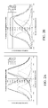
- FIG. 2 a shows a graphical representation of target flux at the substrate for a conventional rotatable cylindrical magnetron arrangement
- FIG. 2 b shows a graphical representation of target flux at the substrate for a rotatable cylindrical magnetron arrangement according to an embodiment of the present invention
- FIG. 3 shows a graphical representation of target flux at the substrate for a rotatable cylindrical magnetron arrangement having a pronounced ripple
- FIG. 4 shows a graphical representation of target flux at the substrate for a rotatable cylindrical magnetron arrangement according to yet another embodiment of the present invention
- FIG. 5 shows optimisations of parameters according to embodiments of the present invention.
- the present invention relates to coating systems and processes that utilize improved magnetrons as hereafter described.
- two magnetrons or three magnetrons are mounted together substantially in parallel. More than three magnetrons can be used with the present invention. Minor differences in dimensions or design details would not negate their ability to properly function together.
- FIG. 1 a is a schematic diagram of a vacuum sputtering system 1 of the kind that can be used with the present invention.
- the magnetron system is for eroding and depositing target material onto a substrate 5 .
- the sputtering may be onto thin film transistors (FPD) for thin film electronics, onto solar absorbers (PV), onto flexible metallic or polymeric substrates, or onto glass substrates.
- the sputtering may be for deposition of oxide layers by a low pressure plasma process at low temperatures in layers for which providing electronic functionality raises the problem of plasma damage of the growing film due to unwanted interaction of fast species with the growing film. This is a problem for semiconductor applications such as processing layers in the nanoscale range for Thin Film Transistor applications or in current spreading layers for LED in optoelectronics and for oxide based p-n junctions.
- the sputtering chamber 2 has a cathode lid 6 and a plurality of horizontally mounted rotatable cylindrical targets 3 a , 3 b . . . , e.g. typically two such cylindrical targets 3 a , 3 b .
- the tubular target 3 a , 3 b may be machined from a relatively thick wall tube, or it may consist of target layer fixed onto a carrier tube.
- Both tubular target layer and the backing tube may rotate when sputtering takes place.
- means for rotating the targets are provided such as one or more motors.
- magnet assemblies 4 a , 4 b that remain stationary as the cylindrical targets are rotated.
- Magnet assemblies 4 a , 4 b create plasma racetracks immediately above the target surface when in operation and the racetracks result in erosion zones on the surfaces of the tubular targets.
- the magnet assemblies include magnets, e.g. lines of magnets of one polarity parallel to the longitudinal axis of the tubular target.
- Each magnet assembly is configured to provide a magnetic field racetrack over the outer surface of each tubular target.
- the magnetic field racetrack confines a plasma gas to erode the target material of each target from a pair of substantially parallel erosion zones along the length of the each tubular target, each pair of erosion zones defining a source plane for each target and being separated by a distance there between, and each magnet assembly configured to fix the distance between the parallel erosion zones in each target to create a combined area of target material flux for each tubular target.
- a greater fraction of the target flux from each target is utilized to deposit target material onto a substrate 5 than from a single zone on each target.
- the magnet assemblies 4 are rotated or tilted relative to the plane of the substrate in opposing directions. Accordingly there are means for tilting the magnet assemblies.
- the magnet assemblies 4 are oriented relative to each other such that, at the substrate, the target flux of each of the targets combines to create an area of substantially uniform flux at the substrate 5 .
- the angular distance (“racetrack angle”) between the parallel erosion zones, subtended at the centre of the cylindrical target is preferably greater than 45°, for example is 45 to 90° or for example 50 to 80°.
- the placement of the substrate with respect to the targets, and the pointing angles of the racetracks toward the substrate and each other are selected to create a uniform target flux over a significant area at the substrate.
- the target to substrate distance can be between 50 and 500 mm.
- one magnet assembly can be oriented with respect to a plane perpendicular to the substrate to subtend an angle of between 5° and 40°.
- the spacing of the axes of the at least first and second targets can be between 40 and 500 mm.
- the diameter of the cylindrical targets can be between 30 and 500 mm.
- the target flux at the substrate is substantially constant with a variability of less than 5%, preferably with a variability of less than 2% more preferably with a variability of less than 1% over a distance of at least 75% of the spacing distance between the axes of the targets of the outermost magnetrons and more preferably over a distance similar (+/ ⁇ 20%) to the spacing distance between the axes of the outermost magnetrons.
- the tubular target includes a target support assembly for holding the target material and for enabling the target material to be rotated with respect to the magnet assembly. Means are provided to rotate the tubular target at a determinable speed. Means are provided for introducing a plasma gas into the sputtering chamber and controlling the gas flow to achieve a determinable density of the plasma gas in the vicinity of the substrate. Means can be provided for introducing a reactive gas into the sputtering chamber and controlling the gas flow to achieve a determinable density of the plasma gas in the vicinity of the substrate.
- the speed of rotation of the targets and the density of the plasma gas at the erosion zones is preferably set to prevent target material from accumulating on the target at a location away from the erosion zones during a rotation of the tubular target.
- the present invention may also include the use of one or more shields to facilitate the removal of target material that did not arrive onto the substrate.
- a separate electrical anode constructed from a conducting material, usually a metal, may be foreseen.
- each pair of erosion zones on a target defines a source plane and planes normal to the source planes in the direction of the substrate intersect with the substrate in such a way that the intersections of the normals to the source planes define first reference planes which intersect with the substrate such that the intersections are spaced along the substrate along the moving direction of the substrate.
- the substrate is positioned such that a line of intersection that is common to both first reference planes normal to the source planes, is well behind the substrate, i.e. on the opposite side of the substrate from the targets.
- the substrate is positioned at a distance nearer to the targets than this intersecting line.
- the two first reference planes may be parallel to each other.
- This geometrical arrangement results in a combination of both fluxes from the targets that has a broad area where the flux is constant (see FIGS. 2B, 4 and 5 ). If the substrate is placed too close to the targets the peaks of flux from the targets become separated on the substrate. Hence a ripple appears within the uniform flux (see FIG. 3 ).
- This ripple can be defined by a Peak-to-Peak value that is defined by dividing the maximum local deposition rate minus the minimum local deposition rate by the average deposition rate within the substrate window of substantially constant flux. The variability is defined by dividing the Peak-to-Peak value by 2. If the substrate is too far from the targets the peaks merge but are wider in extent.
- a target flux from a single erosion zone that is oriented with respect to the substrate typically has a distribution similar to a skewed Gaussian-like curve having a center of distribution and a width (see FIG. 2 b ).
- the width of the Gaussian-like curve can be defined as a distance between two one-half points on the curve.
- the distance between the parallel erosion zones on each target is set so that the target flux at the substrate from the pair of erosion zones is substantially uniform over a field larger than that from a single erosion zone.
- the magnet assembly is fixed with respect to a substrate position.
- the substrate 5 is moved continuously below the cylindrical targets 3 a , 3 b .
- the movement is perpendicular or substantially perpendicular to the longitudinal axes of the cylindrical targets but the present invention is not limited thereto.
- the second rotatable cylindrical tubular target 3 b is positioned relative to the first target 3 a such that axes of the first and second targets 3 a , 3 b are parallel to each other and the outside surfaces of the first and second cylindrical tubular targets 3 a , 3 b are in close proximity.
- All of the magnets of the magnet assemblies 4 a , 4 b point radially away from the geometrical centers of the respective tubular targets 3 a , 3 b .
- Distance “S” between the targets 3 a , 3 b , target-substrate spacing H, the angle between racetracks “X” and the rotation or tilting of the magnet assemblies with respect to each other, “Y”, are selected so that the target flux of the targets combines to create an area of substantially uniform flux at the substrate 5 and hence of uniform thickness and stoichiometry. This is achieved by spreading the sputtered material flux evenly, and by reducing hot zones on the substrate. As shown in FIGS.
- Each magnet assembly 4 can include a support structure constructed from a water resistant magnetic alloy.
- Each magnet assembly includes center and outer magnets arranged so that erosion zones are produced on the target which subtend an angle (the race track angle X) between 45 and 90° or between 50 and 80° at the centre of the cylindrical target. This means that there exist second reference planes, each of which passes through the centre of a target and through the centre of an erosion zone of that target and which subtend an angle of greater than 45°, e.g. between 45 and 90° or 50 and 80°.
- the magnets may have magnet pole pieces. Pole pieces aid in smoothing out the magnetic field produced by magnets if they are constructed from an array of smaller individual magnets.
- the magnets may be arranged in a housing to prevent exposure to the cooling medium.
- the directions of magnetization of magnets may be selected as desired, however, all the magnet assemblies that are used in a given system usually have like magnetic orientation.
- the cross section shape of the magnets may be rectangular or may have irregular shape as to accommodate the desired magnetic field distribution.
- the magnets may be of the rare earth (NeFeB) type, which have very high energy density. They define the erosion zones that are part of the racetrack.
- the magnet assemblies 4 are intentionally constructed to increase the distance between the center and outer magnets compared to prior art designs, to thereby produce erosion zones spaced at large distances while maintaining high magnetic field strength.
- the vacuum sputtering system according to the present invention can be used for high rate reactive deposition of, for example, dielectric thin films at low sputtering gas pressure with both conductive and insulating target materials. This allows the apparatus to produce superior quality dielectric films while maintaining a very constant process over the lifetime of the target tube.
- FIG. 2 a illustrates schematically the relative distribution of sputtered flux from two erosion zones on the substrate according to a conventional arrangement.
- the sputtered flux distribution has the approximate shape of superimposed skewed Gaussian curves.
- the central flux is lower than the peaks on either side and the coating produced may vary in content and thickness.
- the configuration used was: Diameter of target D: 150 mm, Target-substrate spacing H: 80 mm, Spacing of target axis S: 220 mm Race track angle X: 30°, Tilting of race-track Y: 0°. The results shown graphically in FIG.
- Peak-to-Peak variation within 220 mm length of surface on the substrate in the movement direction was: 62% and a yield within a 400 mm window: 84%.
- the zone of uniform sputtered flux is taken the same as the axis spacing of the magnetrons.
- FIG. 2 b illustrates schematically the relative distribution of sputtered flux from two erosion zones on the substrate in accordance with embodiments of the present invention.
- the configuration was as follows: Diameter of target D 147 mm, Target-substrate spacing H: 76 mm, Spacing of target axis S: 223 mm, Race track angle X: 50°, Tilting of race-track Y: 18°.
- the results are shown graphically in FIG. 2 b and were Peak-to-Peak variation within length of 220 mm in movement direction: ⁇ 1%, Yield within 400 mm window: 85%.
- the zone of uniform sputtered flux is taken the same as the axis spacing of the magnetrons.
- the sputtered flux distribution has the approximate shape of a “pork pie hat”. There is a significant area of constant central flux the coating produced is more uniform in content and thickness. With such an arrangement and a constant partial pressure of reactive gas a deposited film on the substrate that has a substantially uniform stoichiometry and thickness.
- the Gaussian-like flux distribution of the second sputtering erosion zone is added to the first. This alignment of the two distributions yields a relatively broad and uniform flux distribution at the substrate.
- FIG. 4 relates to an arrangement according to an embodiment of the present invention with four targets and hence 4 racetracks and 8 erosion zones.
- the central curve is the resulting material flux of the inner two targets and the bimodal curve is the resulting material flux of the outer two targets.
- the top curve with flat zone is the resulting material flux of all 4 targets.
- the inner magnetrons i.e. not the outer magnetron at each side
- the race track angles can be similar for these magnetrons and a similar spacing between the targets and may have similar spacing to the substrate.
- the outer magnetrons i.e.
- 1 target at each side may have slightly higher power level, may have inward tilting of the magnet bar, may have slightly smaller spacing to the substrate.
- An example of a configuration is: racetrack angle for all targets X: 54°, tilting of the outer magnetrons (each inwards): 6°, target diameter D: 150 mm, target-target spacing S: 190 mm, number of magnetron sets: 2, power level per magnetron: first: 100%, second 100%, target-substrate spacing H: first: 149 mm, second 121 mm.
- the results are shown schematically in FIG. 4 and are: uniformity min: 99%, max. 100.1%, Peak-to-Peak variation 0.2%.
- all targets can be placed so that they have the same target-substrate spacing and the coating uniformity can be controlled by setting the power level in the outer magnetrons.
- FIG. 5 shows an optimisation of parameters according to embodiments of the present invention. All the points on the graphs relate to a uniform sputter zone perpendicular to target axis depending on the criteria:
- the sputtering process is preferably also stabilized and controlled by fixing parameters such as pumping speed, plasma (i.e. sputtering) gas flow, reactive gas flow, power supply voltage, substrate speed all of which are simply held constant during deposition.
- fixing parameters such as pumping speed, plasma (i.e. sputtering) gas flow, reactive gas flow, power supply voltage, substrate speed all of which are simply held constant during deposition.
- the embodiments described above use a racetrack angle of above 45° and the examples show that a higher sputter rate is obtained with better uniformity.
- the reactive gas partial pressure can be reduced to react fully at the location where the largest flux of target particles is arriving. Further, at this working point; the target is less poisoned and may realize a higher sputter rate for the same power level.
- the compound formation is much more homogeneous over the formed layer thickness. Thus higher performing TCO's may be realized with the same target materials. Hence, the compound formation is not different depending on the local flux of target particles arriving at the substrate. Also it is less necessary for TCO's to make a trade-off between conductivity and layer transmittance.
Abstract
Description
-
- Uniform zone (+/−1%) from 100 mm to 450 mm with one dual configuration
- Constraints on spacings (between targets and substrate) and angles
- Simulating change in target diameter and target-substrate spacing over target lifetime
- Sensitivity analysis on each variable.
Claims (17)
Applications Claiming Priority (4)
| Application Number | Priority Date | Filing Date | Title |
|---|---|---|---|
| EP10191612 | 2010-11-17 | ||
| EP10191612 | 2010-11-17 | ||
| EP10191612.0 | 2010-11-17 | ||
| PCT/EP2011/070357 WO2012066079A1 (en) | 2010-11-17 | 2011-11-17 | Soft sputtering magnetron system |
Publications (2)
| Publication Number | Publication Date |
|---|---|
| US20130228452A1 US20130228452A1 (en) | 2013-09-05 |
| US9394603B2 true US9394603B2 (en) | 2016-07-19 |
Family
ID=43411508
Family Applications (1)
| Application Number | Title | Priority Date | Filing Date |
|---|---|---|---|
| US13/885,905 Active 2032-08-09 US9394603B2 (en) | 2010-11-17 | 2011-11-17 | Soft sputtering magnetron system |
Country Status (5)
| Country | Link |
|---|---|
| US (1) | US9394603B2 (en) |
| EP (1) | EP2640865B1 (en) |
| JP (1) | JP6118258B2 (en) |
| KR (1) | KR20140003440A (en) |
| WO (1) | WO2012066079A1 (en) |
Families Citing this family (13)
| Publication number | Priority date | Publication date | Assignee | Title |
|---|---|---|---|---|
| US20160189939A1 (en) * | 2012-03-12 | 2016-06-30 | Applied Materials, Inc. | Mini rotatable sputter devices for sputter deposition |
| JP2013237913A (en) * | 2012-05-16 | 2013-11-28 | Ulvac Japan Ltd | Sputtering apparatus and sputtering method |
| GB201216138D0 (en) * | 2012-09-11 | 2012-10-24 | Gencoa Ltd | Plasma source |
| BE1021296B1 (en) * | 2014-04-18 | 2015-10-23 | Soleras Advanced Coatings Bvba | SPUTTER SYSTEM FOR UNIFORM SPUTTERING |
| WO2016005476A1 (en) * | 2014-07-09 | 2016-01-14 | Soleras Advanced Coatings Bvba | Sputter device with moving target |
| KR20170082619A (en) * | 2014-12-17 | 2017-07-14 | (주)울텍 | sputtering magnetron |
| CN104694892A (en) * | 2015-03-27 | 2015-06-10 | 京东方科技集团股份有限公司 | Sputtering device |
| DE102015113454A1 (en) * | 2015-08-14 | 2017-02-16 | Von Ardenne Gmbh | Reactive sputtering assembly and method |
| KR20180032523A (en) | 2016-03-30 | 2018-03-30 | 케이힌 람테크 가부시키가이샤 | Sputtering cathode, sputtering apparatus and manufacturing method of film forming element |
| CN109983150B (en) * | 2016-11-22 | 2022-04-26 | 应用材料公司 | Apparatus and method for depositing a layer on a substrate |
| WO2018186038A1 (en) * | 2017-04-03 | 2018-10-11 | 株式会社アルバック | Film forming device and film forming method |
| JP7097172B2 (en) * | 2017-11-21 | 2022-07-07 | キヤノントッキ株式会社 | Sputtering equipment |
| WO2020196307A1 (en) * | 2019-03-26 | 2020-10-01 | 日東電工株式会社 | Magnetron plasma deposition apparatus |
Citations (8)
| Publication number | Priority date | Publication date | Assignee | Title |
|---|---|---|---|---|
| WO1992001081A1 (en) * | 1990-07-06 | 1992-01-23 | The Boc Group, Inc. | Method and apparatus for co-sputtering and cross-sputtering homogeneous films |
| US5100527A (en) * | 1990-10-18 | 1992-03-31 | Viratec Thin Films, Inc. | Rotating magnetron incorporating a removable cathode |
| DE4117367A1 (en) | 1991-05-28 | 1992-12-03 | Leybold Ag | Modifying magnetic field in sputter equipment with rotating target - results in a box-shaped profile of material removal on the target surface which improves the efficiency and reduced penetration danger |
| WO2000028104A1 (en) | 1998-11-06 | 2000-05-18 | Scivac | Sputtering apparatus and process for high rate coatings |
| US20050109616A1 (en) * | 2003-10-28 | 2005-05-26 | Konica Minolta Opto, Inc. | Sputtering apparatus |
| US20070089983A1 (en) | 2005-10-24 | 2007-04-26 | Soleras Ltd. | Cathode incorporating fixed or rotating target in combination with a moving magnet assembly and applications thereof |
| US20090283400A1 (en) | 2008-05-14 | 2009-11-19 | Applied Materials, Inc. | Microwave-assisted rotatable pvd |
| US20100187104A1 (en) | 2007-06-25 | 2010-07-29 | Kabushiki Kaisha Kobe Seiko Sho(Kobe Steel, Ltd.) | Film formation apparatus |
Family Cites Families (1)
| Publication number | Priority date | Publication date | Assignee | Title |
|---|---|---|---|---|
| US4466877A (en) | 1983-10-11 | 1984-08-21 | Shatterproof Glass Corporation | Magnetron cathode sputtering apparatus |
-
2011
- 2011-11-17 WO PCT/EP2011/070357 patent/WO2012066079A1/en active Application Filing
- 2011-11-17 KR KR1020137015643A patent/KR20140003440A/en active Search and Examination
- 2011-11-17 JP JP2013539259A patent/JP6118258B2/en active Active
- 2011-11-17 US US13/885,905 patent/US9394603B2/en active Active
- 2011-11-17 EP EP11826114.8A patent/EP2640865B1/en active Active
Patent Citations (10)
| Publication number | Priority date | Publication date | Assignee | Title |
|---|---|---|---|---|
| WO1992001081A1 (en) * | 1990-07-06 | 1992-01-23 | The Boc Group, Inc. | Method and apparatus for co-sputtering and cross-sputtering homogeneous films |
| US5100527A (en) * | 1990-10-18 | 1992-03-31 | Viratec Thin Films, Inc. | Rotating magnetron incorporating a removable cathode |
| DE4117367A1 (en) | 1991-05-28 | 1992-12-03 | Leybold Ag | Modifying magnetic field in sputter equipment with rotating target - results in a box-shaped profile of material removal on the target surface which improves the efficiency and reduced penetration danger |
| WO2000028104A1 (en) | 1998-11-06 | 2000-05-18 | Scivac | Sputtering apparatus and process for high rate coatings |
| US6365010B1 (en) | 1998-11-06 | 2002-04-02 | Scivac | Sputtering apparatus and process for high rate coatings |
| JP2002529600A (en) | 1998-11-06 | 2002-09-10 | シヴァク | Sputtering apparatus and method for high rate coating |
| US20050109616A1 (en) * | 2003-10-28 | 2005-05-26 | Konica Minolta Opto, Inc. | Sputtering apparatus |
| US20070089983A1 (en) | 2005-10-24 | 2007-04-26 | Soleras Ltd. | Cathode incorporating fixed or rotating target in combination with a moving magnet assembly and applications thereof |
| US20100187104A1 (en) | 2007-06-25 | 2010-07-29 | Kabushiki Kaisha Kobe Seiko Sho(Kobe Steel, Ltd.) | Film formation apparatus |
| US20090283400A1 (en) | 2008-05-14 | 2009-11-19 | Applied Materials, Inc. | Microwave-assisted rotatable pvd |
Non-Patent Citations (1)
| Title |
|---|
| International Search Report issued in PCT/EP2011/070357, Apr. 12, 2012. |
Also Published As
| Publication number | Publication date |
|---|---|
| JP6118258B2 (en) | 2017-04-19 |
| WO2012066079A1 (en) | 2012-05-24 |
| KR20140003440A (en) | 2014-01-09 |
| US20130228452A1 (en) | 2013-09-05 |
| EP2640865B1 (en) | 2020-05-13 |
| EP2640865A1 (en) | 2013-09-25 |
| JP2014500398A (en) | 2014-01-09 |
Similar Documents
| Publication | Publication Date | Title |
|---|---|---|
| US9394603B2 (en) | Soft sputtering magnetron system | |
| US6365010B1 (en) | Sputtering apparatus and process for high rate coatings | |
| US6488824B1 (en) | Sputtering apparatus and process for high rate coatings | |
| US8382966B2 (en) | Sputtering system | |
| US20120273343A1 (en) | Method for coating a substrate and coater | |
| EP2855729B1 (en) | Method for coating a substrate and coater | |
| US5558750A (en) | Process and system for coating a substrate | |
| TWI557252B (en) | Cathode assembly for a sputter deposition apparatus and method for depositing a film on a substrate in a sputter deposition apparatus | |
| KR100848851B1 (en) | Plasma damage free sputter gun, sputter, plasma process apparatus and film-forming method | |
| WO1992001081A1 (en) | Method and apparatus for co-sputtering and cross-sputtering homogeneous films | |
| JP2002509988A (en) | Method and apparatus for depositing a biaxially textured coating | |
| US20080296142A1 (en) | Swinging magnets to improve target utilization | |
| TW201608044A (en) | Sputter deposition apparatus and method for coating a substrate by rotary target assemblies in two coating regions and use thereof | |
| TWM592875U (en) | Tilted magnetron in a pvd sputtering deposition chamber | |
| WO2012066080A1 (en) | Sputtering apparatus and method | |
| WO2017182081A1 (en) | Method for coating a substrate and coater | |
| Seyfert et al. | 40 years of industrial magnetron sputtering in Europe | |
| JP2020019991A (en) | Film deposition device and electronic device manufacturing method | |
| WO2018095514A1 (en) | Apparatus and method for layer deposition on a substrate | |
| KR20220153636A (en) | Apparatus and Process Using DC Pulsed Cathode Arrays | |
| US8852412B2 (en) | Magnetron source and method of manufacturing | |
| JP2020200520A (en) | Film deposition apparatus, sputtering target mechanism and film deposition method | |
| US20080023319A1 (en) | Magnetron assembly | |
| US11668003B2 (en) | Deposition system with a multi-cathode | |
| JP4877058B2 (en) | Opposing target sputtering apparatus and method |
Legal Events
| Date | Code | Title | Description |
|---|---|---|---|
| AS | Assignment |
Owner name: SOLERAS ADVANCED COATINGS BVBA, BELGIUM Free format text: ASSIGNMENT OF ASSIGNORS INTEREST;ASSIGNOR:DE BOSSCHER, WILLIAM;REEL/FRAME:030430/0839 Effective date: 20130515 |
|
| AS | Assignment |
Owner name: SOLERAS ADVANCED COATINGS BVBA, BELGIUM Free format text: CORRECTIVE ASSIGNMENT TO CORRECT THE TYPOGRAHICAL ERROR IN THE ASSIGNOR'S NAME AND ASSIGNEE'S ADDRESS PREVIOUSLY RECORDED AT REEL: 030430 FRAME: 0839. ASSIGNOR(S) HEREBY CONFIRMS THE ASSIGNMENT;ASSIGNOR:DE BOSSCHER, WILMERT;REEL/FRAME:038695/0924 Effective date: 20130515 |
|
| STCF | Information on status: patent grant |
Free format text: PATENTED CASE |
|
| FEPP | Fee payment procedure |
Free format text: ENTITY STATUS SET TO SMALL (ORIGINAL EVENT CODE: SMAL); ENTITY STATUS OF PATENT OWNER: SMALL ENTITY |
|
| MAFP | Maintenance fee payment |
Free format text: PAYMENT OF MAINTENANCE FEE, 4TH YR, SMALL ENTITY (ORIGINAL EVENT CODE: M2551); ENTITY STATUS OF PATENT OWNER: SMALL ENTITY Year of fee payment: 4 |
|
| MAFP | Maintenance fee payment |
Free format text: PAYMENT OF MAINTENANCE FEE, 8TH YR, SMALL ENTITY (ORIGINAL EVENT CODE: M2552); ENTITY STATUS OF PATENT OWNER: SMALL ENTITY Year of fee payment: 8 |