US9387087B2 - Orthopedic systems for spine and tracking control - Google Patents
Orthopedic systems for spine and tracking control Download PDFInfo
- Publication number
- US9387087B2 US9387087B2 US14/054,100 US201314054100A US9387087B2 US 9387087 B2 US9387087 B2 US 9387087B2 US 201314054100 A US201314054100 A US 201314054100A US 9387087 B2 US9387087 B2 US 9387087B2
- Authority
- US
- United States
- Prior art keywords
- screw
- peaks
- extending
- plate
- orthopedic implant
- Prior art date
- Legal status (The legal status is an assumption and is not a legal conclusion. Google has not performed a legal analysis and makes no representation as to the accuracy of the status listed.)
- Active, expires
Links
Images


Classifications
-
- A—HUMAN NECESSITIES
- A61—MEDICAL OR VETERINARY SCIENCE; HYGIENE
- A61F—FILTERS IMPLANTABLE INTO BLOOD VESSELS; PROSTHESES; DEVICES PROVIDING PATENCY TO, OR PREVENTING COLLAPSING OF, TUBULAR STRUCTURES OF THE BODY, e.g. STENTS; ORTHOPAEDIC, NURSING OR CONTRACEPTIVE DEVICES; FOMENTATION; TREATMENT OR PROTECTION OF EYES OR EARS; BANDAGES, DRESSINGS OR ABSORBENT PADS; FIRST-AID KITS
- A61F2/00—Filters implantable into blood vessels; Prostheses, i.e. artificial substitutes or replacements for parts of the body; Appliances for connecting them with the body; Devices providing patency to, or preventing collapsing of, tubular structures of the body, e.g. stents
- A61F2/02—Prostheses implantable into the body
- A61F2/30—Joints
- A61F2/44—Joints for the spine, e.g. vertebrae, spinal discs
- A61F2/4455—Joints for the spine, e.g. vertebrae, spinal discs for the fusion of spinal bodies, e.g. intervertebral fusion of adjacent spinal bodies, e.g. fusion cages
-
- A—HUMAN NECESSITIES
- A61—MEDICAL OR VETERINARY SCIENCE; HYGIENE
- A61B—DIAGNOSIS; SURGERY; IDENTIFICATION
- A61B17/00—Surgical instruments, devices or methods
- A61B17/56—Surgical instruments or methods for treatment of bones or joints; Devices specially adapted therefor
- A61B17/58—Surgical instruments or methods for treatment of bones or joints; Devices specially adapted therefor for osteosynthesis, e.g. bone plates, screws or setting implements
- A61B17/68—Internal fixation devices, including fasteners and spinal fixators, even if a part thereof projects from the skin
- A61B17/70—Spinal positioners or stabilisers, e.g. stabilisers comprising fluid filler in an implant
- A61B17/7059—Cortical plates
-
- A—HUMAN NECESSITIES
- A61—MEDICAL OR VETERINARY SCIENCE; HYGIENE
- A61B—DIAGNOSIS; SURGERY; IDENTIFICATION
- A61B17/00—Surgical instruments, devices or methods
- A61B17/56—Surgical instruments or methods for treatment of bones or joints; Devices specially adapted therefor
- A61B17/58—Surgical instruments or methods for treatment of bones or joints; Devices specially adapted therefor for osteosynthesis, e.g. bone plates, screws or setting implements
- A61B17/68—Internal fixation devices, including fasteners and spinal fixators, even if a part thereof projects from the skin
- A61B17/80—Cortical plates, i.e. bone plates; Instruments for holding or positioning cortical plates, or for compressing bones attached to cortical plates
- A61B17/8052—Cortical plates, i.e. bone plates; Instruments for holding or positioning cortical plates, or for compressing bones attached to cortical plates immobilised relative to screws by interlocking form of the heads and plate holes, e.g. conical or threaded
-
- A—HUMAN NECESSITIES
- A61—MEDICAL OR VETERINARY SCIENCE; HYGIENE
- A61B—DIAGNOSIS; SURGERY; IDENTIFICATION
- A61B17/00—Surgical instruments, devices or methods
- A61B17/56—Surgical instruments or methods for treatment of bones or joints; Devices specially adapted therefor
- A61B17/58—Surgical instruments or methods for treatment of bones or joints; Devices specially adapted therefor for osteosynthesis, e.g. bone plates, screws or setting implements
- A61B17/68—Internal fixation devices, including fasteners and spinal fixators, even if a part thereof projects from the skin
- A61B17/80—Cortical plates, i.e. bone plates; Instruments for holding or positioning cortical plates, or for compressing bones attached to cortical plates
- A61B17/8095—Wedge osteotomy devices
-
- A—HUMAN NECESSITIES
- A61—MEDICAL OR VETERINARY SCIENCE; HYGIENE
- A61B—DIAGNOSIS; SURGERY; IDENTIFICATION
- A61B17/00—Surgical instruments, devices or methods
- A61B17/56—Surgical instruments or methods for treatment of bones or joints; Devices specially adapted therefor
- A61B17/58—Surgical instruments or methods for treatment of bones or joints; Devices specially adapted therefor for osteosynthesis, e.g. bone plates, screws or setting implements
- A61B17/68—Internal fixation devices, including fasteners and spinal fixators, even if a part thereof projects from the skin
- A61B17/84—Fasteners therefor or fasteners being internal fixation devices
- A61B17/86—Pins or screws or threaded wires; nuts therefor
- A61B17/8625—Shanks, i.e. parts contacting bone tissue
- A61B17/863—Shanks, i.e. parts contacting bone tissue with thread interrupted or changing its form along shank, other than constant taper
-
- A—HUMAN NECESSITIES
- A61—MEDICAL OR VETERINARY SCIENCE; HYGIENE
- A61B—DIAGNOSIS; SURGERY; IDENTIFICATION
- A61B17/00—Surgical instruments, devices or methods
- A61B17/56—Surgical instruments or methods for treatment of bones or joints; Devices specially adapted therefor
- A61B17/58—Surgical instruments or methods for treatment of bones or joints; Devices specially adapted therefor for osteosynthesis, e.g. bone plates, screws or setting implements
- A61B17/68—Internal fixation devices, including fasteners and spinal fixators, even if a part thereof projects from the skin
- A61B17/84—Fasteners therefor or fasteners being internal fixation devices
- A61B17/86—Pins or screws or threaded wires; nuts therefor
- A61B17/865—Packages or dispensers for bone screws or threaded wires
-
- A—HUMAN NECESSITIES
- A61—MEDICAL OR VETERINARY SCIENCE; HYGIENE
- A61B—DIAGNOSIS; SURGERY; IDENTIFICATION
- A61B90/00—Instruments, implements or accessories specially adapted for surgery or diagnosis and not covered by any of the groups A61B1/00 - A61B50/00, e.g. for luxation treatment or for protecting wound edges
- A61B90/90—Identification means for patients or instruments, e.g. tags
- A61B90/94—Identification means for patients or instruments, e.g. tags coded with symbols, e.g. text
-
- A—HUMAN NECESSITIES
- A61—MEDICAL OR VETERINARY SCIENCE; HYGIENE
- A61F—FILTERS IMPLANTABLE INTO BLOOD VESSELS; PROSTHESES; DEVICES PROVIDING PATENCY TO, OR PREVENTING COLLAPSING OF, TUBULAR STRUCTURES OF THE BODY, e.g. STENTS; ORTHOPAEDIC, NURSING OR CONTRACEPTIVE DEVICES; FOMENTATION; TREATMENT OR PROTECTION OF EYES OR EARS; BANDAGES, DRESSINGS OR ABSORBENT PADS; FIRST-AID KITS
- A61F2/00—Filters implantable into blood vessels; Prostheses, i.e. artificial substitutes or replacements for parts of the body; Appliances for connecting them with the body; Devices providing patency to, or preventing collapsing of, tubular structures of the body, e.g. stents
- A61F2/02—Prostheses implantable into the body
- A61F2/30—Joints
- A61F2/44—Joints for the spine, e.g. vertebrae, spinal discs
- A61F2/4455—Joints for the spine, e.g. vertebrae, spinal discs for the fusion of spinal bodies, e.g. intervertebral fusion of adjacent spinal bodies, e.g. fusion cages
- A61F2/4465—Joints for the spine, e.g. vertebrae, spinal discs for the fusion of spinal bodies, e.g. intervertebral fusion of adjacent spinal bodies, e.g. fusion cages having a circular or kidney shaped cross-section substantially perpendicular to the axis of the spine
-
- A—HUMAN NECESSITIES
- A61—MEDICAL OR VETERINARY SCIENCE; HYGIENE
- A61F—FILTERS IMPLANTABLE INTO BLOOD VESSELS; PROSTHESES; DEVICES PROVIDING PATENCY TO, OR PREVENTING COLLAPSING OF, TUBULAR STRUCTURES OF THE BODY, e.g. STENTS; ORTHOPAEDIC, NURSING OR CONTRACEPTIVE DEVICES; FOMENTATION; TREATMENT OR PROTECTION OF EYES OR EARS; BANDAGES, DRESSINGS OR ABSORBENT PADS; FIRST-AID KITS
- A61F2/00—Filters implantable into blood vessels; Prostheses, i.e. artificial substitutes or replacements for parts of the body; Appliances for connecting them with the body; Devices providing patency to, or preventing collapsing of, tubular structures of the body, e.g. stents
- A61F2/02—Prostheses implantable into the body
- A61F2/30—Joints
- A61F2/44—Joints for the spine, e.g. vertebrae, spinal discs
- A61F2/4455—Joints for the spine, e.g. vertebrae, spinal discs for the fusion of spinal bodies, e.g. intervertebral fusion of adjacent spinal bodies, e.g. fusion cages
- A61F2/447—Joints for the spine, e.g. vertebrae, spinal discs for the fusion of spinal bodies, e.g. intervertebral fusion of adjacent spinal bodies, e.g. fusion cages substantially parallelepipedal, e.g. having a rectangular or trapezoidal cross-section
-
- A—HUMAN NECESSITIES
- A61—MEDICAL OR VETERINARY SCIENCE; HYGIENE
- A61F—FILTERS IMPLANTABLE INTO BLOOD VESSELS; PROSTHESES; DEVICES PROVIDING PATENCY TO, OR PREVENTING COLLAPSING OF, TUBULAR STRUCTURES OF THE BODY, e.g. STENTS; ORTHOPAEDIC, NURSING OR CONTRACEPTIVE DEVICES; FOMENTATION; TREATMENT OR PROTECTION OF EYES OR EARS; BANDAGES, DRESSINGS OR ABSORBENT PADS; FIRST-AID KITS
- A61F2/00—Filters implantable into blood vessels; Prostheses, i.e. artificial substitutes or replacements for parts of the body; Appliances for connecting them with the body; Devices providing patency to, or preventing collapsing of, tubular structures of the body, e.g. stents
- A61F2/02—Prostheses implantable into the body
- A61F2/30—Joints
- A61F2/46—Special tools for implanting artificial joints
- A61F2/4603—Special tools for implanting artificial joints for insertion or extraction of endoprosthetic joints or of accessories thereof
- A61F2/4611—Special tools for implanting artificial joints for insertion or extraction of endoprosthetic joints or of accessories thereof of spinal prostheses
-
- A—HUMAN NECESSITIES
- A61—MEDICAL OR VETERINARY SCIENCE; HYGIENE
- A61B—DIAGNOSIS; SURGERY; IDENTIFICATION
- A61B17/00—Surgical instruments, devices or methods
- A61B17/56—Surgical instruments or methods for treatment of bones or joints; Devices specially adapted therefor
- A61B17/58—Surgical instruments or methods for treatment of bones or joints; Devices specially adapted therefor for osteosynthesis, e.g. bone plates, screws or setting implements
- A61B17/68—Internal fixation devices, including fasteners and spinal fixators, even if a part thereof projects from the skin
- A61B17/84—Fasteners therefor or fasteners being internal fixation devices
- A61B17/86—Pins or screws or threaded wires; nuts therefor
- A61B17/8645—Headless screws, e.g. ligament interference screws
-
- A—HUMAN NECESSITIES
- A61—MEDICAL OR VETERINARY SCIENCE; HYGIENE
- A61F—FILTERS IMPLANTABLE INTO BLOOD VESSELS; PROSTHESES; DEVICES PROVIDING PATENCY TO, OR PREVENTING COLLAPSING OF, TUBULAR STRUCTURES OF THE BODY, e.g. STENTS; ORTHOPAEDIC, NURSING OR CONTRACEPTIVE DEVICES; FOMENTATION; TREATMENT OR PROTECTION OF EYES OR EARS; BANDAGES, DRESSINGS OR ABSORBENT PADS; FIRST-AID KITS
- A61F2/00—Filters implantable into blood vessels; Prostheses, i.e. artificial substitutes or replacements for parts of the body; Appliances for connecting them with the body; Devices providing patency to, or preventing collapsing of, tubular structures of the body, e.g. stents
- A61F2/02—Prostheses implantable into the body
- A61F2/30—Joints
- A61F2/30767—Special external or bone-contacting surface, e.g. coating for improving bone ingrowth
- A61F2/30771—Special external or bone-contacting surface, e.g. coating for improving bone ingrowth applied in original prostheses, e.g. holes or grooves
-
- A—HUMAN NECESSITIES
- A61—MEDICAL OR VETERINARY SCIENCE; HYGIENE
- A61F—FILTERS IMPLANTABLE INTO BLOOD VESSELS; PROSTHESES; DEVICES PROVIDING PATENCY TO, OR PREVENTING COLLAPSING OF, TUBULAR STRUCTURES OF THE BODY, e.g. STENTS; ORTHOPAEDIC, NURSING OR CONTRACEPTIVE DEVICES; FOMENTATION; TREATMENT OR PROTECTION OF EYES OR EARS; BANDAGES, DRESSINGS OR ABSORBENT PADS; FIRST-AID KITS
- A61F2/00—Filters implantable into blood vessels; Prostheses, i.e. artificial substitutes or replacements for parts of the body; Appliances for connecting them with the body; Devices providing patency to, or preventing collapsing of, tubular structures of the body, e.g. stents
- A61F2/02—Prostheses implantable into the body
- A61F2/30—Joints
- A61F2/46—Special tools for implanting artificial joints
- A61F2/4603—Special tools for implanting artificial joints for insertion or extraction of endoprosthetic joints or of accessories thereof
-
- A—HUMAN NECESSITIES
- A61—MEDICAL OR VETERINARY SCIENCE; HYGIENE
- A61F—FILTERS IMPLANTABLE INTO BLOOD VESSELS; PROSTHESES; DEVICES PROVIDING PATENCY TO, OR PREVENTING COLLAPSING OF, TUBULAR STRUCTURES OF THE BODY, e.g. STENTS; ORTHOPAEDIC, NURSING OR CONTRACEPTIVE DEVICES; FOMENTATION; TREATMENT OR PROTECTION OF EYES OR EARS; BANDAGES, DRESSINGS OR ABSORBENT PADS; FIRST-AID KITS
- A61F2/00—Filters implantable into blood vessels; Prostheses, i.e. artificial substitutes or replacements for parts of the body; Appliances for connecting them with the body; Devices providing patency to, or preventing collapsing of, tubular structures of the body, e.g. stents
- A61F2/02—Prostheses implantable into the body
- A61F2/30—Joints
- A61F2002/30001—Additional features of subject-matter classified in A61F2/28, A61F2/30 and subgroups thereof
- A61F2002/30003—Material related properties of the prosthesis or of a coating on the prosthesis
- A61F2002/30004—Material related properties of the prosthesis or of a coating on the prosthesis the prosthesis being made from materials having different values of a given property at different locations within the same prosthesis
- A61F2002/30011—Material related properties of the prosthesis or of a coating on the prosthesis the prosthesis being made from materials having different values of a given property at different locations within the same prosthesis differing in porosity
-
- A61F2002/30013—
-
- A—HUMAN NECESSITIES
- A61—MEDICAL OR VETERINARY SCIENCE; HYGIENE
- A61F—FILTERS IMPLANTABLE INTO BLOOD VESSELS; PROSTHESES; DEVICES PROVIDING PATENCY TO, OR PREVENTING COLLAPSING OF, TUBULAR STRUCTURES OF THE BODY, e.g. STENTS; ORTHOPAEDIC, NURSING OR CONTRACEPTIVE DEVICES; FOMENTATION; TREATMENT OR PROTECTION OF EYES OR EARS; BANDAGES, DRESSINGS OR ABSORBENT PADS; FIRST-AID KITS
- A61F2/00—Filters implantable into blood vessels; Prostheses, i.e. artificial substitutes or replacements for parts of the body; Appliances for connecting them with the body; Devices providing patency to, or preventing collapsing of, tubular structures of the body, e.g. stents
- A61F2/02—Prostheses implantable into the body
- A61F2/30—Joints
- A61F2002/30001—Additional features of subject-matter classified in A61F2/28, A61F2/30 and subgroups thereof
- A61F2002/30003—Material related properties of the prosthesis or of a coating on the prosthesis
- A61F2002/3006—Properties of materials and coating materials
- A61F2002/3008—Properties of materials and coating materials radio-opaque, e.g. radio-opaque markers
-
- A—HUMAN NECESSITIES
- A61—MEDICAL OR VETERINARY SCIENCE; HYGIENE
- A61F—FILTERS IMPLANTABLE INTO BLOOD VESSELS; PROSTHESES; DEVICES PROVIDING PATENCY TO, OR PREVENTING COLLAPSING OF, TUBULAR STRUCTURES OF THE BODY, e.g. STENTS; ORTHOPAEDIC, NURSING OR CONTRACEPTIVE DEVICES; FOMENTATION; TREATMENT OR PROTECTION OF EYES OR EARS; BANDAGES, DRESSINGS OR ABSORBENT PADS; FIRST-AID KITS
- A61F2/00—Filters implantable into blood vessels; Prostheses, i.e. artificial substitutes or replacements for parts of the body; Appliances for connecting them with the body; Devices providing patency to, or preventing collapsing of, tubular structures of the body, e.g. stents
- A61F2/02—Prostheses implantable into the body
- A61F2/30—Joints
- A61F2002/30001—Additional features of subject-matter classified in A61F2/28, A61F2/30 and subgroups thereof
- A61F2002/30108—Shapes
- A61F2002/30199—Three-dimensional shapes
- A61F2002/3028—Three-dimensional shapes polyhedral different from parallelepipedal and pyramidal
- A61F2002/30281—Three-dimensional shapes polyhedral different from parallelepipedal and pyramidal wedge-shaped
-
- A—HUMAN NECESSITIES
- A61—MEDICAL OR VETERINARY SCIENCE; HYGIENE
- A61F—FILTERS IMPLANTABLE INTO BLOOD VESSELS; PROSTHESES; DEVICES PROVIDING PATENCY TO, OR PREVENTING COLLAPSING OF, TUBULAR STRUCTURES OF THE BODY, e.g. STENTS; ORTHOPAEDIC, NURSING OR CONTRACEPTIVE DEVICES; FOMENTATION; TREATMENT OR PROTECTION OF EYES OR EARS; BANDAGES, DRESSINGS OR ABSORBENT PADS; FIRST-AID KITS
- A61F2/00—Filters implantable into blood vessels; Prostheses, i.e. artificial substitutes or replacements for parts of the body; Appliances for connecting them with the body; Devices providing patency to, or preventing collapsing of, tubular structures of the body, e.g. stents
- A61F2/02—Prostheses implantable into the body
- A61F2/30—Joints
- A61F2002/30001—Additional features of subject-matter classified in A61F2/28, A61F2/30 and subgroups thereof
- A61F2002/30316—The prosthesis having different structural features at different locations within the same prosthesis; Connections between prosthetic parts; Special structural features of bone or joint prostheses not otherwise provided for
- A61F2002/30329—Connections or couplings between prosthetic parts, e.g. between modular parts; Connecting elements
- A61F2002/30331—Connections or couplings between prosthetic parts, e.g. between modular parts; Connecting elements made by longitudinally pushing a protrusion into a complementarily-shaped recess, e.g. held by friction fit
- A61F2002/30354—Cylindrically-shaped protrusion and recess, e.g. cylinder of circular basis
- A61F2002/30355—Cylinder of elliptical or oval basis
-
- A—HUMAN NECESSITIES
- A61—MEDICAL OR VETERINARY SCIENCE; HYGIENE
- A61F—FILTERS IMPLANTABLE INTO BLOOD VESSELS; PROSTHESES; DEVICES PROVIDING PATENCY TO, OR PREVENTING COLLAPSING OF, TUBULAR STRUCTURES OF THE BODY, e.g. STENTS; ORTHOPAEDIC, NURSING OR CONTRACEPTIVE DEVICES; FOMENTATION; TREATMENT OR PROTECTION OF EYES OR EARS; BANDAGES, DRESSINGS OR ABSORBENT PADS; FIRST-AID KITS
- A61F2/00—Filters implantable into blood vessels; Prostheses, i.e. artificial substitutes or replacements for parts of the body; Appliances for connecting them with the body; Devices providing patency to, or preventing collapsing of, tubular structures of the body, e.g. stents
- A61F2/02—Prostheses implantable into the body
- A61F2/30—Joints
- A61F2002/30001—Additional features of subject-matter classified in A61F2/28, A61F2/30 and subgroups thereof
- A61F2002/30316—The prosthesis having different structural features at different locations within the same prosthesis; Connections between prosthetic parts; Special structural features of bone or joint prostheses not otherwise provided for
- A61F2002/30329—Connections or couplings between prosthetic parts, e.g. between modular parts; Connecting elements
- A61F2002/30476—Connections or couplings between prosthetic parts, e.g. between modular parts; Connecting elements locked by an additional locking mechanism
- A61F2002/30507—Connections or couplings between prosthetic parts, e.g. between modular parts; Connecting elements locked by an additional locking mechanism using a threaded locking member, e.g. a locking screw or a set screw
-
- A61F2002/30509—
-
- A—HUMAN NECESSITIES
- A61—MEDICAL OR VETERINARY SCIENCE; HYGIENE
- A61F—FILTERS IMPLANTABLE INTO BLOOD VESSELS; PROSTHESES; DEVICES PROVIDING PATENCY TO, OR PREVENTING COLLAPSING OF, TUBULAR STRUCTURES OF THE BODY, e.g. STENTS; ORTHOPAEDIC, NURSING OR CONTRACEPTIVE DEVICES; FOMENTATION; TREATMENT OR PROTECTION OF EYES OR EARS; BANDAGES, DRESSINGS OR ABSORBENT PADS; FIRST-AID KITS
- A61F2/00—Filters implantable into blood vessels; Prostheses, i.e. artificial substitutes or replacements for parts of the body; Appliances for connecting them with the body; Devices providing patency to, or preventing collapsing of, tubular structures of the body, e.g. stents
- A61F2/02—Prostheses implantable into the body
- A61F2/30—Joints
- A61F2002/30001—Additional features of subject-matter classified in A61F2/28, A61F2/30 and subgroups thereof
- A61F2002/30316—The prosthesis having different structural features at different locations within the same prosthesis; Connections between prosthetic parts; Special structural features of bone or joint prostheses not otherwise provided for
- A61F2002/30535—Special structural features of bone or joint prostheses not otherwise provided for
- A61F2002/30576—Special structural features of bone or joint prostheses not otherwise provided for with extending fixation tabs
- A61F2002/30578—Special structural features of bone or joint prostheses not otherwise provided for with extending fixation tabs having apertures, e.g. for receiving fixation screws
-
- A—HUMAN NECESSITIES
- A61—MEDICAL OR VETERINARY SCIENCE; HYGIENE
- A61F—FILTERS IMPLANTABLE INTO BLOOD VESSELS; PROSTHESES; DEVICES PROVIDING PATENCY TO, OR PREVENTING COLLAPSING OF, TUBULAR STRUCTURES OF THE BODY, e.g. STENTS; ORTHOPAEDIC, NURSING OR CONTRACEPTIVE DEVICES; FOMENTATION; TREATMENT OR PROTECTION OF EYES OR EARS; BANDAGES, DRESSINGS OR ABSORBENT PADS; FIRST-AID KITS
- A61F2/00—Filters implantable into blood vessels; Prostheses, i.e. artificial substitutes or replacements for parts of the body; Appliances for connecting them with the body; Devices providing patency to, or preventing collapsing of, tubular structures of the body, e.g. stents
- A61F2/02—Prostheses implantable into the body
- A61F2/30—Joints
- A61F2002/30001—Additional features of subject-matter classified in A61F2/28, A61F2/30 and subgroups thereof
- A61F2002/30316—The prosthesis having different structural features at different locations within the same prosthesis; Connections between prosthetic parts; Special structural features of bone or joint prostheses not otherwise provided for
- A61F2002/30535—Special structural features of bone or joint prostheses not otherwise provided for
- A61F2002/30593—Special structural features of bone or joint prostheses not otherwise provided for hollow
-
- A—HUMAN NECESSITIES
- A61—MEDICAL OR VETERINARY SCIENCE; HYGIENE
- A61F—FILTERS IMPLANTABLE INTO BLOOD VESSELS; PROSTHESES; DEVICES PROVIDING PATENCY TO, OR PREVENTING COLLAPSING OF, TUBULAR STRUCTURES OF THE BODY, e.g. STENTS; ORTHOPAEDIC, NURSING OR CONTRACEPTIVE DEVICES; FOMENTATION; TREATMENT OR PROTECTION OF EYES OR EARS; BANDAGES, DRESSINGS OR ABSORBENT PADS; FIRST-AID KITS
- A61F2/00—Filters implantable into blood vessels; Prostheses, i.e. artificial substitutes or replacements for parts of the body; Appliances for connecting them with the body; Devices providing patency to, or preventing collapsing of, tubular structures of the body, e.g. stents
- A61F2/02—Prostheses implantable into the body
- A61F2/30—Joints
- A61F2002/30001—Additional features of subject-matter classified in A61F2/28, A61F2/30 and subgroups thereof
- A61F2002/30667—Features concerning an interaction with the environment or a particular use of the prosthesis
- A61F2002/3071—Identification means; Administration of patients
-
- A61F2002/30714—
-
- A—HUMAN NECESSITIES
- A61—MEDICAL OR VETERINARY SCIENCE; HYGIENE
- A61F—FILTERS IMPLANTABLE INTO BLOOD VESSELS; PROSTHESES; DEVICES PROVIDING PATENCY TO, OR PREVENTING COLLAPSING OF, TUBULAR STRUCTURES OF THE BODY, e.g. STENTS; ORTHOPAEDIC, NURSING OR CONTRACEPTIVE DEVICES; FOMENTATION; TREATMENT OR PROTECTION OF EYES OR EARS; BANDAGES, DRESSINGS OR ABSORBENT PADS; FIRST-AID KITS
- A61F2/00—Filters implantable into blood vessels; Prostheses, i.e. artificial substitutes or replacements for parts of the body; Appliances for connecting them with the body; Devices providing patency to, or preventing collapsing of, tubular structures of the body, e.g. stents
- A61F2/02—Prostheses implantable into the body
- A61F2/30—Joints
- A61F2/30767—Special external or bone-contacting surface, e.g. coating for improving bone ingrowth
- A61F2/30771—Special external or bone-contacting surface, e.g. coating for improving bone ingrowth applied in original prostheses, e.g. holes or grooves
- A61F2002/30772—Apertures or holes, e.g. of circular cross section
- A61F2002/30774—Apertures or holes, e.g. of circular cross section internally-threaded
-
- A—HUMAN NECESSITIES
- A61—MEDICAL OR VETERINARY SCIENCE; HYGIENE
- A61F—FILTERS IMPLANTABLE INTO BLOOD VESSELS; PROSTHESES; DEVICES PROVIDING PATENCY TO, OR PREVENTING COLLAPSING OF, TUBULAR STRUCTURES OF THE BODY, e.g. STENTS; ORTHOPAEDIC, NURSING OR CONTRACEPTIVE DEVICES; FOMENTATION; TREATMENT OR PROTECTION OF EYES OR EARS; BANDAGES, DRESSINGS OR ABSORBENT PADS; FIRST-AID KITS
- A61F2/00—Filters implantable into blood vessels; Prostheses, i.e. artificial substitutes or replacements for parts of the body; Appliances for connecting them with the body; Devices providing patency to, or preventing collapsing of, tubular structures of the body, e.g. stents
- A61F2/02—Prostheses implantable into the body
- A61F2/30—Joints
- A61F2/30767—Special external or bone-contacting surface, e.g. coating for improving bone ingrowth
- A61F2/30771—Special external or bone-contacting surface, e.g. coating for improving bone ingrowth applied in original prostheses, e.g. holes or grooves
- A61F2002/30795—Blind bores, e.g. of circular cross-section
- A61F2002/30807—Plurality of blind bores
- A61F2002/30808—Plurality of blind bores parallel
-
- A—HUMAN NECESSITIES
- A61—MEDICAL OR VETERINARY SCIENCE; HYGIENE
- A61F—FILTERS IMPLANTABLE INTO BLOOD VESSELS; PROSTHESES; DEVICES PROVIDING PATENCY TO, OR PREVENTING COLLAPSING OF, TUBULAR STRUCTURES OF THE BODY, e.g. STENTS; ORTHOPAEDIC, NURSING OR CONTRACEPTIVE DEVICES; FOMENTATION; TREATMENT OR PROTECTION OF EYES OR EARS; BANDAGES, DRESSINGS OR ABSORBENT PADS; FIRST-AID KITS
- A61F2/00—Filters implantable into blood vessels; Prostheses, i.e. artificial substitutes or replacements for parts of the body; Appliances for connecting them with the body; Devices providing patency to, or preventing collapsing of, tubular structures of the body, e.g. stents
- A61F2/02—Prostheses implantable into the body
- A61F2/30—Joints
- A61F2/30767—Special external or bone-contacting surface, e.g. coating for improving bone ingrowth
- A61F2/30771—Special external or bone-contacting surface, e.g. coating for improving bone ingrowth applied in original prostheses, e.g. holes or grooves
- A61F2002/3082—Grooves
-
- A—HUMAN NECESSITIES
- A61—MEDICAL OR VETERINARY SCIENCE; HYGIENE
- A61F—FILTERS IMPLANTABLE INTO BLOOD VESSELS; PROSTHESES; DEVICES PROVIDING PATENCY TO, OR PREVENTING COLLAPSING OF, TUBULAR STRUCTURES OF THE BODY, e.g. STENTS; ORTHOPAEDIC, NURSING OR CONTRACEPTIVE DEVICES; FOMENTATION; TREATMENT OR PROTECTION OF EYES OR EARS; BANDAGES, DRESSINGS OR ABSORBENT PADS; FIRST-AID KITS
- A61F2/00—Filters implantable into blood vessels; Prostheses, i.e. artificial substitutes or replacements for parts of the body; Appliances for connecting them with the body; Devices providing patency to, or preventing collapsing of, tubular structures of the body, e.g. stents
- A61F2/02—Prostheses implantable into the body
- A61F2/30—Joints
- A61F2/30767—Special external or bone-contacting surface, e.g. coating for improving bone ingrowth
- A61F2/30771—Special external or bone-contacting surface, e.g. coating for improving bone ingrowth applied in original prostheses, e.g. holes or grooves
- A61F2002/30836—Special external or bone-contacting surface, e.g. coating for improving bone ingrowth applied in original prostheses, e.g. holes or grooves knurled
-
- A—HUMAN NECESSITIES
- A61—MEDICAL OR VETERINARY SCIENCE; HYGIENE
- A61F—FILTERS IMPLANTABLE INTO BLOOD VESSELS; PROSTHESES; DEVICES PROVIDING PATENCY TO, OR PREVENTING COLLAPSING OF, TUBULAR STRUCTURES OF THE BODY, e.g. STENTS; ORTHOPAEDIC, NURSING OR CONTRACEPTIVE DEVICES; FOMENTATION; TREATMENT OR PROTECTION OF EYES OR EARS; BANDAGES, DRESSINGS OR ABSORBENT PADS; FIRST-AID KITS
- A61F2/00—Filters implantable into blood vessels; Prostheses, i.e. artificial substitutes or replacements for parts of the body; Appliances for connecting them with the body; Devices providing patency to, or preventing collapsing of, tubular structures of the body, e.g. stents
- A61F2/02—Prostheses implantable into the body
- A61F2/30—Joints
- A61F2/30767—Special external or bone-contacting surface, e.g. coating for improving bone ingrowth
- A61F2/30771—Special external or bone-contacting surface, e.g. coating for improving bone ingrowth applied in original prostheses, e.g. holes or grooves
- A61F2002/30841—Sharp anchoring protrusions for impaction into the bone, e.g. sharp pins, spikes
- A61F2002/30843—Pyramidally-shaped
-
- A—HUMAN NECESSITIES
- A61—MEDICAL OR VETERINARY SCIENCE; HYGIENE
- A61F—FILTERS IMPLANTABLE INTO BLOOD VESSELS; PROSTHESES; DEVICES PROVIDING PATENCY TO, OR PREVENTING COLLAPSING OF, TUBULAR STRUCTURES OF THE BODY, e.g. STENTS; ORTHOPAEDIC, NURSING OR CONTRACEPTIVE DEVICES; FOMENTATION; TREATMENT OR PROTECTION OF EYES OR EARS; BANDAGES, DRESSINGS OR ABSORBENT PADS; FIRST-AID KITS
- A61F2/00—Filters implantable into blood vessels; Prostheses, i.e. artificial substitutes or replacements for parts of the body; Appliances for connecting them with the body; Devices providing patency to, or preventing collapsing of, tubular structures of the body, e.g. stents
- A61F2/02—Prostheses implantable into the body
- A61F2/30—Joints
- A61F2/30767—Special external or bone-contacting surface, e.g. coating for improving bone ingrowth
- A61F2002/3092—Special external or bone-contacting surface, e.g. coating for improving bone ingrowth having an open-celled or open-pored structure
-
- A—HUMAN NECESSITIES
- A61—MEDICAL OR VETERINARY SCIENCE; HYGIENE
- A61F—FILTERS IMPLANTABLE INTO BLOOD VESSELS; PROSTHESES; DEVICES PROVIDING PATENCY TO, OR PREVENTING COLLAPSING OF, TUBULAR STRUCTURES OF THE BODY, e.g. STENTS; ORTHOPAEDIC, NURSING OR CONTRACEPTIVE DEVICES; FOMENTATION; TREATMENT OR PROTECTION OF EYES OR EARS; BANDAGES, DRESSINGS OR ABSORBENT PADS; FIRST-AID KITS
- A61F2/00—Filters implantable into blood vessels; Prostheses, i.e. artificial substitutes or replacements for parts of the body; Appliances for connecting them with the body; Devices providing patency to, or preventing collapsing of, tubular structures of the body, e.g. stents
- A61F2/02—Prostheses implantable into the body
- A61F2/30—Joints
- A61F2/30767—Special external or bone-contacting surface, e.g. coating for improving bone ingrowth
- A61F2002/3093—Special external or bone-contacting surface, e.g. coating for improving bone ingrowth for promoting ingrowth of bone tissue
-
- A61F2002/4475—
-
- A61F2002/4623—
-
- A—HUMAN NECESSITIES
- A61—MEDICAL OR VETERINARY SCIENCE; HYGIENE
- A61F—FILTERS IMPLANTABLE INTO BLOOD VESSELS; PROSTHESES; DEVICES PROVIDING PATENCY TO, OR PREVENTING COLLAPSING OF, TUBULAR STRUCTURES OF THE BODY, e.g. STENTS; ORTHOPAEDIC, NURSING OR CONTRACEPTIVE DEVICES; FOMENTATION; TREATMENT OR PROTECTION OF EYES OR EARS; BANDAGES, DRESSINGS OR ABSORBENT PADS; FIRST-AID KITS
- A61F2/00—Filters implantable into blood vessels; Prostheses, i.e. artificial substitutes or replacements for parts of the body; Appliances for connecting them with the body; Devices providing patency to, or preventing collapsing of, tubular structures of the body, e.g. stents
- A61F2/02—Prostheses implantable into the body
- A61F2/30—Joints
- A61F2/46—Special tools for implanting artificial joints
- A61F2/4603—Special tools for implanting artificial joints for insertion or extraction of endoprosthetic joints or of accessories thereof
- A61F2002/4625—Special tools for implanting artificial joints for insertion or extraction of endoprosthetic joints or of accessories thereof with relative movement between parts of the instrument during use
- A61F2002/4627—Special tools for implanting artificial joints for insertion or extraction of endoprosthetic joints or of accessories thereof with relative movement between parts of the instrument during use with linear motion along or rotating motion about the instrument axis or the implantation direction, e.g. telescopic, along a guiding rod, screwing inside the instrument
-
- A—HUMAN NECESSITIES
- A61—MEDICAL OR VETERINARY SCIENCE; HYGIENE
- A61F—FILTERS IMPLANTABLE INTO BLOOD VESSELS; PROSTHESES; DEVICES PROVIDING PATENCY TO, OR PREVENTING COLLAPSING OF, TUBULAR STRUCTURES OF THE BODY, e.g. STENTS; ORTHOPAEDIC, NURSING OR CONTRACEPTIVE DEVICES; FOMENTATION; TREATMENT OR PROTECTION OF EYES OR EARS; BANDAGES, DRESSINGS OR ABSORBENT PADS; FIRST-AID KITS
- A61F2310/00—Prostheses classified in A61F2/28 or A61F2/30 - A61F2/44 being constructed from or coated with a particular material
- A61F2310/00389—The prosthesis being coated or covered with a particular material
- A61F2310/00395—Coating or prosthesis-covering structure made of metals or of alloys
- A61F2310/00407—Coating made of titanium or of Ti-based alloys
-
- A—HUMAN NECESSITIES
- A61—MEDICAL OR VETERINARY SCIENCE; HYGIENE
- A61F—FILTERS IMPLANTABLE INTO BLOOD VESSELS; PROSTHESES; DEVICES PROVIDING PATENCY TO, OR PREVENTING COLLAPSING OF, TUBULAR STRUCTURES OF THE BODY, e.g. STENTS; ORTHOPAEDIC, NURSING OR CONTRACEPTIVE DEVICES; FOMENTATION; TREATMENT OR PROTECTION OF EYES OR EARS; BANDAGES, DRESSINGS OR ABSORBENT PADS; FIRST-AID KITS
- A61F2310/00—Prostheses classified in A61F2/28 or A61F2/30 - A61F2/44 being constructed from or coated with a particular material
- A61F2310/00389—The prosthesis being coated or covered with a particular material
- A61F2310/00395—Coating or prosthesis-covering structure made of metals or of alloys
- A61F2310/00419—Other metals
- A61F2310/00461—Coating made of nickel or Ni-based alloys
-
- A—HUMAN NECESSITIES
- A61—MEDICAL OR VETERINARY SCIENCE; HYGIENE
- A61F—FILTERS IMPLANTABLE INTO BLOOD VESSELS; PROSTHESES; DEVICES PROVIDING PATENCY TO, OR PREVENTING COLLAPSING OF, TUBULAR STRUCTURES OF THE BODY, e.g. STENTS; ORTHOPAEDIC, NURSING OR CONTRACEPTIVE DEVICES; FOMENTATION; TREATMENT OR PROTECTION OF EYES OR EARS; BANDAGES, DRESSINGS OR ABSORBENT PADS; FIRST-AID KITS
- A61F2310/00—Prostheses classified in A61F2/28 or A61F2/30 - A61F2/44 being constructed from or coated with a particular material
- A61F2310/00389—The prosthesis being coated or covered with a particular material
- A61F2310/00592—Coating or prosthesis-covering structure made of ceramics or of ceramic-like compounds
- A61F2310/00796—Coating or prosthesis-covering structure made of a phosphorus-containing compound, e.g. hydroxy(l)apatite
Definitions
- the present invention generally relates to an orthopedic systems for treatment of the spine specifically intervertebral implants, containing mechanism to rigidly attach to the vertebrae and systems for full lot control traceability.
- Anterior intervertebral interbody fusion is a common technique for treating degenerative disc disease and major deformity.
- the anterior approach is common for both the cervical (ACIF) and lumbar (ALIF) spine.
- the approach allows full visibility of the disc and fusion site, while minimizing disruptions to the branch nerves of the spinal column as well as major trauma to the posterior musculature.
- Typical intervertebral fusion consists of an interbody spacer and a fixation means, such as anterior plate or posterior pedicle screws.
- An objective of the interbody spacer is to maintain the height of the intervertebral space, but allow for bone to grow through the interbody spacer to form a fused mass between vertebrae.
- the interbody spacers are constructed from inert biocompatible material such as titanium or polyether-ether-ketone (PEEK). Titanium is typically used in orthopedic systems due to its strength and osteoconductive properties. However, in intervertebral spacers, titanium is not the preferred choice due to its high stiffness compared with bone. The large stiffness differential between bone and titanium has caused a high incidence of subsidence of the implant into the vertebral body. This has led the way for other biomaterials being selected for the spacer's body material. PEEK is a common interbody material selected because the Young's Modulus is extremely similar to bone and the material is extremely inert. However, PEEK is not an osteoconductive material and a large central oval cavity is the only space designed for bone through growth, thus the spacers remove a larger percentage of the fusion area.
- inert biocompatible material such as titanium or polyether-ether-ketone (PEEK). Titanium is typically used in orthopedic systems due to its strength and osteoconductive properties.
- PEEK polyether-ether-
- an intervertebral implant in accordance with one exemplary embodiment of invention, includes an upper surface generally conforming to a plane and lower surface generally conforming to a plane. A series of longitudinal grooves located on both upper and lower planes and a series of transverse grooves form a peak. A generally centrally located cavity pierces the upper and lower planes and surfaces. The implant further contains the means to contain a permanent osteoconductive material on all peaks on both the upper and lower planes.
- an intervertebral implant in a second exemplary embodiment of the invention, includes an upper surface generally conforming to a plane and lower surface generally conforming to a plane.
- a centrally located threaded aperture for adaption to an insertion instrument.
- a second centrally located recess is configured in a rectangular shape to prevent rotation of mating mechanisms.
- an insertion instrument in a third exemplary embodiment of the invention, includes a handle attached a hollow cylindrical tube attached to an engagement end.
- the engagement end contains a fastener for securing to an implant which can be activated by activating a cam.
- the engagement end containing a positive stop for controlling the depth and distance of the implant.
- an implant in a fourth exemplary embodiment of the invention, includes a plate designed to cooperatively attach to the intervertebral implant with an engagement mechanism.
- the engagement mechanism having a generally rectangular shape is located on the posterior plane of the implant and extending from the plane.
- a locking screw is designed to cooperatively attach to the plate implant and secure the intervertebral implant to a fixed position.
- an implant in a fifth exemplary embodiment of the invention, includes a plate, adaptable to an intervertebral implant, and bone screws, where the bone screws contain cantilever segments.
- the cantilever segments deform during insertion of the bone screws into a recess.
- the recess generally containing a cylindrical section, an undercut and a round seat, with the undercut preventing the cantilever segments from backing out after insertion.
- a removable implant body extension contains descriptive information regarding the implant.
- the descriptive information contains lot number and/or serial number of the connected implant, allowing removal of the body extension to aid in tracing the implant.
- the removable body extension is adaptable for single cycle sterilization or multiple cycle sterilization.
- a bone screw contains a distal thread and a proximal thread connected by a shaft. Where the distal thread contains a distal pitch and the proximal screw contains a proximal pitch with the distal pitch being greater than the proximal pitch.
- FIG. 1 is a perspective view of an intervertebral implant in accordance with one exemplary embodiment of the invention
- FIG. 2 is a top view of the implant of FIG. 1 ;
- FIG. 3 is a front view of the implant of FIG. 1 ;
- FIG. 4 is a side view of the implant of FIG. 1 ;
- FIG. 5 is a rear view of the implant of FIG. 1 ;
- FIG. 6 is a cross section view of the intervertebral implant of FIG. 1 , showing a hole configuration
- FIG. 7 is a side view of the implant of FIG. 1 with a first alternative exemplary type of surface
- FIG. 8 is a side view of the implant of FIG. 1 with a second alternative exemplary type of surface
- FIG. 9 is a micrograph showing distribution of titanium on a PEEK substrate, providing an illustrative exemplary composition of the invention.
- FIG. 10 is a perspective view of an alternative exemplary embodiment view of an insertion instrument
- FIG. 11 is an enlarged perspective view of an insertion instrument of FIG. 10 , engagement end;
- FIG. 12( a ) is a cross section view of the insertion instrument of FIG. 10 , showing the attachment mechanism;
- FIG. 12( b ) is an enlarged truncated cross section view of the insertion instrument implant attachment of FIG. 10 ;
- FIG. 13 is an enlarged axial view of the insertion instrument of FIG. 10 , showing visualization of the alignment features;
- FIG. 14 is a top of view of the insertion instrument of FIG. 10 ;
- FIG. 15 is a perspective view of a plate for attachment to an intervertebral implant of FIG. 1 , in accordance with one exemplary embodiment of the invention.
- FIG. 16 is a side view of the implant of FIG. 15 ;
- FIG. 17 is a perspective view of a plate's posterior side showing rectangular connection of the plate shown in FIG. 15 ;
- FIG. 18 is a perspective view of the plate shown in FIG. 15 , attached to intervertebral implant of FIG. 1 , with attachment mechanism;
- FIG. 19 is a side cross section view of the plate and intervertebral implant assembly of FIG. 18 , showing connection means;
- FIG. 20 is a top cross section view of the plate and intervertebral implant assembly of FIG. 18 , showing connection means;
- FIG. 21 is a perspective view of a fully configured plate and intervertebral implant, shown in FIG. 18 , with bone screws, in accordance with another exemplary embodiment of the invention.
- FIG. 22 is a side view of the fully configured plate and intervertebral implant assembly of FIG. 21 ;
- FIG. 23 is a perspective view of a fifth exemplary embodiment, showing a bone screw with cantilever segments
- FIG. 24 is a truncated cross section view of the bone screw shown in FIG. 23 , inserted into the plate shown in FIG. 15 , in a non-locked state;
- FIG. 25 is a truncated cross section view of the bone screw of FIG. 23 , inserted into the plate shown in FIG. 15 , in a locked state;
- FIG. 26 is a perspective view of a sixth exemplary embodiment, showing a bone screw with removable body extension
- FIG. 27( a ) is a side view of a bone screw with removal body extension shown in FIG. 26 , showing descriptive information;
- FIG. 27( b ) is a further rotated side view of a bone screw with removal body extension shown in FIG. 26 , showing descriptive information;
- FIG. 28 is a cross section view of bone screw with removal body extension shown in FIG. 26 ;
- FIG. 29 is a side view of a removal body extension showing descriptive information
- FIG. 30 is a perspective view showing the removable body extension of FIG. 29 , attached to the plate shown in FIG. 15 ;
- FIG. 31 is a perspective view of a sixth exemplary embodiment, showing a bone screw
- FIG. 32 is another perspective view of the bone screw shown in FIG. 31 ;
- FIG. 33 is another side view of the showing a bone screw shown in FIG. 31 ;
- FIG. 34 is a top view showing the bone screw of FIG. 31 ;
- FIG. 35 is a cross sectional view showing the bone screw shown in FIG. 31 ;
- FIG. 36 is an enlarged view of the proximal end of the bone screw shown in FIG. 31 ;
- FIG. 37 is an enlarged view of the shaft of the bone screw shown in FIG. 31 ;
- FIG. 38 is an enlarged view of the distal end of the bone screw shown in FIG. 31 .
- anterior refers to features having a relative position toward the front side of a spine
- posterior refers to features having a relative position toward the rear side of the spine
- superiorior refers to features having a relative position above other features, in the cranial direction
- inferior refers to features having a relative position below other features in a caudal direction.
- the terminology includes the words specifically mentioned, derivatives thereof and words of similar import.
- exemplary is used herein to mean serving as an example, instance, or illustration. Any aspect or design described herein as “exemplary” is not necessarily to be construed as preferred or advantageous over other aspects or designs. Rather, use of the word exemplary is intended to present concepts in a concrete fashion.
- the term “or” is intended to mean an inclusive “or” rather than an exclusive “or”. That is, unless specified otherwise, or clear from context, “X employs A or B” is intended to mean any of the natural inclusive permutations. That is, if X employs A; X employs B; or X employs both A and B, then “X employs A or B” is satisfied under any of the foregoing instances.
- the articles “a” and “an” as used in this application and the appended claims should generally be construed to mean “one or more” unless specified otherwise or clear from context to be directed to a singular form.
- Interbody cages constructed from rigid materials such as titanium tend to have a large Young's modulus in the range of 105-130 GPa compared to bone, which has a relatively low modulus of 1.8 GPa. This makes titanium at least 58 times stiffer than bone and clinical studies have concluded this as the main cause of subsidence within the vertebral endplates. Subsidence is where the implant breaks through the vertebral endplates and intervertebral spacing is lost. Subsidence has been linked to pseudo-arthrosis, non-unions and re-operations of the fusion site.
- the high material stiffness may also enhance stress shielding of the central graft preventing or delaying bone through growth.
- the surface of titanium is well known for its osteoconductive properties. Osteoconductive materials encourage cell adhesion to the surface and can act like bone itself. This property can be used to increase the fusion area and allow bone growth directly on the implant.
- PEEK The other well utilized material for intervertebral spacers is PEEK.
- PEEK is a semicrystalline thermoplastic with excellent mechanical and chemical resistance properties that are retained to high temperatures.
- intervertebral spacers constructed from PEEK have found a growing usage due to their relatively low stiffness, approximately 3.6 GPa compared to 1.8 GPa for bone.
- Clinical literature has reported lower occurrences of subsidence with PEEK intervertebral spacers, compared to a titanium spacer.
- PEEK is not an osteoconductive material and as such placement of a PEEK spacer within the intervertebral disc space can reduce the fusion area 60-70%, thus lowering the chances of a full fusion.
- the intervertebral spacers of the present invention improve upon prior approaches by addressing the subsidence and settling of the endplates, while maximizing the fusion area.
- the various embodiments of the present invention allow proper load distribution through the use of low stiffness material enabling the load to transfer through the bone graft material during implant settling, while increasing the fusion area and reducing the mitigation risks.
- the embodiments include an osteoconductive material, such as titanium, applied on a substrate with similar properties to bone.
- the inferior and superior surfaces are configured to maximize the surface area through the use of a rectangular pyramid shaped tooth.
- the assembly also includes a mechanism which can engage both an insertion instrument and supplemental hardware, such as a plate and screw assembly.
- Interbody spacer 100 in accordance with one exemplary embodiment of the invention is shown.
- Interbody assemblies in accordance with the present invention may include a variety of body and teeth configurations.
- Interbody spacer 100 includes a rigid body 111 and a plurality of peaks, or teeth, 112 which form rigid body 111 .
- Rigid body 111 has an anterior surface 113 and a posterior surface 114 that is generally parallel to the anterior surface.
- Anterior surface 113 has a larger external surface area than posterior surface 114 .
- Anterior and posterior surfaces 113 , 114 are joined by a pair of lateral side surfaces 115 that extend generally radially to one another.
- a superior end surface 116 extends generally in a first plane and an inferior end surface 117 extends generally in a second plane obliquely, in a non-parallel manner, to the first plane between anterior side surface 113 and posterior side surface 114 .
- Superior and inferior end surfaces 116 , 117 taper or converge toward one another as end surfaces 116 , 117 extend toward posterior side surface 114 , forming a wedge-shaped structure.
- the anterior, posterior and lateral side surfaces, 113 , 114 , and 115 surround a generally centrally located cavity 118 that forms a space for fusion material, such as a bone graft or bone graft substitute.
- Interbody spacer 100 includes a recess 120 extending through anterior surface 113 inwardly toward cavity 118 and generally centered between the superior 116 and inferior 117 surfaces.
- Recess 120 allows for the alignment of a congruent extension 1012 from either an instrument such as an insertion instrument 1000 , shown in FIG. 10 , or an implant assembly such as plate assembly 1500 , shown in FIG. 15 .
- An aperture 119 is centrally located within the recess 120 between the anterior surface 113 and the cavity 118 .
- the aperture 119 may be configured in either a threaded configuration, interference configuration or any means to secure the interbody spacer 100 to a separate device.
- FIG. 2 illustrates a top view of the interbody spacer 100 having a generally oval shape. This shape is generated by rounding the anterior 113 , posterior 114 , and lateral surfaces 115 , as well as the corner surfaces 211 .
- the central opening 118 can be constructed by creating a uniform offset of the outer perimeter 213 .
- the interbody spacer 100 benefits from a uniform geometry allowing the interbody to more evenly distribute the load distribution on the vertebral endplates.
- the center line A-P is defined by a line passing from the anterior surface 113 to the posterior surface 114 .
- the L-L line is defined by a line passing from the lateral surface 115 to the other lateral surface 115 .
- the teeth 112 are formed by adjacent ones of a plurality of anterior grooves 311 (shown in FIG. 3 ) traversing longitudinally along the A-P direction and a plurality of lateral grooves 411 (shown in FIG. 4 ) traversing transversely along the L-L direction.
- the intersection of anterior groove 311 and lateral groove 411 create a four sided pyramid-like tooth that maximize the surface area of superior surface 116 and inferior surface 117 . While a four sided tooth is shown, those skilled in the art will recognize that tooth (not shown) can have more or less than four sides.
- the teeth 112 are used to grip the superior and inferior endplate of the vertebral body (not shown).
- FIG. 3 illustrates the interbody spacer 100 from the anterior direction and shows the recess 120 and aperture 119 .
- the recess 120 is defined by parallel edge 312 , which forms a line segment and can be used to block rotation of congruent extension 1012 during insertion of the interbody spacer 100 into a patient (not shown).
- the teeth 112 are defined by the “V” shaped anterior groove 311 , however this groove can be a “U” shaped groove, “L” shape groove, “O” shape groove or any other configuration of groove which is create by a low peak (or trough) 314 , a high peak 315 , and peak width 316 .
- FIG. 4 illustrated a side profile of an interbody spacer 100 , which is shown as having a non-symmetric shape 400 .
- the implant superior surface 116 ′ and inferior surface 117 ′ cannot be mirrored about the A-P axis, thus defining the non-symmetric shape.
- the superior surface 117 ′ is defined by a superior convex dome 412 in an anterior-posterior direction, which is used to match the inferior vertebral endplate, not shown.
- the teeth 112 viewed from a lateral direction are constructed from an “L” shape groove 413 in the L-L direction. In order to maintain equal distance between peaks 315 on a domed surface, the teeth 112 must repeat at a crest angle ( ⁇ ), where crest angle ⁇ is greater than 0 degrees.
- Exemplary values for crest angle ⁇ may be between about 0 degrees and about 90 degrees. In an exemplary embodiment, crest angle ⁇ is about 10 degrees.
- the surfaces of adjacent peaks that define angle ⁇ extend generally perpendicular to the domed surface.
- the inferior surface 117 ′ teeth 112 are parallel to the A-P line and crest angle ⁇ is approximately 0 degrees between high peaks 315 .
- FIG. 5 shows a posterior view of the interbody spacer 400 , which shows the overall wedge shaped.
- the posterior surface 114 is a wedge shape to aid in the insertion of the interbody spacer 100 into the vertebral disc space.
- FIG. 6 shows the cross-sectional view of the interbody spacer 100 as well as the recess 120 , aperture 119 and a marker bore 612 .
- the recess 120 extends sufficiently into the interbody rigid body 111 enough to create a parallel edge 312 .
- the aperture 119 extends from the recess 312 into the central opening 118 .
- Marker bore 612 generally is a cylindrical in shape, however this can be rectangular, triangular, or other suitable shape. Marker bore 612 is used to insert marker 1251 (shown in FIG. 12 b ), which can be constructed from any radiopaque material, such as stainless steel, titanium, tantalum, etc.
- the markers 1251 when viewed from an anterior direction, show the interbody spacer's 100 width, which is defined from lateral surface 115 to opposing surface lateral surface 115 .
- the markers 1251 when viewed from the lateral position show the depth of the implant. The depth is defined as the distance between the anterior surface 113 and the posterior surface 114 .
- FIGS. 7 and 8 show side views of an alternative embodiment of curved symmetric interbody spacer 700 and straight symmetric interbody spacer 800 , respectively, where the superior surface 116 and inferior surface 117 are symmetric about the A-P line.
- symmetrical interbody spacers 700 and 800 may mate with the opposing vertebral endplates better than a non-symmetric interbody spacer 400 .
- the symmetric interbodies 700 and 800 are defined when the superior dome 412 or superior surface 116 can be mirrored about the A-P centerline to be equivalent to the inferior dome 711 or inferior surface 117 .
- the width of rear crest 714 is generally larger than the width of mid crest 716 , which allows for the interbody spacers 400 , 700 and 800 to wedge itself between the vertebral endplates.
- the rear crest 714 can be aided by aligning the superior 116 and inferior 117 surfaces at an angle 812 from the A-P centerline.
- angle 812 can be between about 0 degrees and about 90 degrees.
- the angle 812 can be used to match the spine curvature, such as Kyphosis or Lordosis angles.
- FIG. 9 is a micrograph of a cross sectional cut of a substrate 910 and porous coating 912 on the surface of an interbody spacer 100 , including at least one side of each of the teeth 112 .
- the thickness of porous coating 912 can be between about 25 ⁇ m and about 800 ⁇ m thick.
- the substrate 910 can be any polymeric material, such as PEEK, Polymethyl Methacrylate (PMMA), or any other biocompatible polymer with a Young's modulus between about 0.1 GPa and about 50 GPa, which may be used as the interbody spacer 100 .
- the porous coating 912 is constructed from an osteoconductive material, such as titanium, nickel titanium, or any other material which may encourage bone in growth.
- the porous coating 912 is rigidly bounded to substrate 910 through a bonded layer 911 , such as by a plasma spray, vapor deposition, or another other surface additive method.
- the pores substrate 912 contains small to large size cavities 914 , which encourage bone in-growth and attachment.
- the porosity of the pores substrate 912 can be between about 5 percent and about 80 percent porous.
- the interbody spacer 100 superior dome 412 and superior surface 116 are coated with the porous coating 912 , as is the inferior dome 711 and inferior surfaces 117 .
- the coating allows the interbody spacer rigid body 111 to maintain the low stiffness, which can be constructed from PEEK or low stiffness polymer, while gaining the porous coating 912 with osteoconductive properties.
- a hydroxyapatite coating can be applied on surfaces 113 , 114 , 115 and on the walls of cavity 118 to enhance for visualization of implant 100 after implementation.
- FIGS. 10-14 Another embodiment of the invention is the insertion instrument 1000 illustrated in FIGS. 10-14 , which is used to insert interbody 100 into the spine.
- the insertion instrument 1000 must capture the interbody spacer 100 , position the interbody spacer 100 , and deploy the interbody spacer 100 in between two adjacent vertebral bodies (not shown).
- the insertion instrument 1000 has a handle 1010 used to grip the instrument and rear end 1020 that can cooperate with an impact device (not shown).
- the hollow shaft 1016 is of a smaller diameter than the handle and has enough length to maneuver around soft tissue.
- Located between the shaft 1016 and handle 1010 has a cam 1018 used to engage and disengage a drive shaft 1252 from the aperture 119 in the interbody spacer 100 .
- a fastener portion, or engagement end 1014 is located at the opposite end from the rear end 1020 .
- the engagement end 1014 is illustrated in FIGS. 11-12 b and is designed to releasably engage the interbody spacer 100 .
- the engagement end 1014 contains an engagement extension 1112 , which is located at the end of the drive shaft 1252 .
- the engagement extension 1112 is centrally located within the congruent extension 1012 , which is defined by two parallel edges 1120 .
- the congruent extension 1012 must contain at least one parallel edge 1114 but can be in a circular, rectangular, hexagonal, triangular or oblong.
- the engagement end 1014 may also have depth stop 1115 , which is used to control the placement of the interbody spacer 100 within the intervertebral disc space. The height of the depth stops 1115 must be greater than the highest interbody spacer 100 .
- FIGS. 12-14 illustrate the attachment of the interbody spacer 100 to the insertion instrument 1000 .
- the interbody spacer 100 is positioned at the engagement end 1014 of the insertion instrument 1000 .
- the engagement extension 1112 is coaxially aligned with and inserted into the implant aperture 119 in the recess 120 and the cam 1018 is rotated.
- the cam 1018 translates rotational motion through the drive shaft 1252 and extends engagement extension 1112 , until engagement is achieved.
- the engagement extension 1112 and aperture 119 have matching threads, however engagement may also be completed by an interference fit or other suitable engagement means.
- the rotation of the cam 1018 draws the interbody spacer 100 until contact is achieved with depth stops 1115 .
- the interbody spacer 100 is then placed into position by using an impaction device (not shown), such as, for example, a mallet, a hammer, a slap hammer, or other such device, on the rear end 1020 until the depth stops 1114 are flush with the surface of the vertebral bodies (not shown).
- the cam 1018 is then rotated in the reverse (unlocking) direction to retract engagement extension 1112 inwardly into shaft 1016 in the direction of arrow “A” in FIG. 12 a , and the engagement extension 1112 is then removed from interbody spacer 100 .
- an impaction device such as, for example, a mallet, a hammer, a slap hammer, or other such device
- indicator arrows 613 point towards the superior surface 116 and superior dome 412 .
- the surgeon needs to visualize these indicator arrows 613 and the insertion instrument 1000 depth stop 1115 must have a width 1310 small enough to visualize the arrows 613 .
- the plate assembly 1500 contains a rigid body 1508 , which is defined by anterior surface 1510 , posterior surface 1512 , and an external perimeter 1518 .
- the plate has a generally “dog bone” shape but can have a rectangular, square or triangular shape.
- the plate 1500 includes at least two screw recesses 1520 .
- Located in the center of the plate is a generally frusto-conical countersunk surface 1542 and attachment aperture 1540 .
- the attachment aperture 1540 is designed to align coaxially with the interbody spacer 100 aperture 119 and has an equal or larger diameter than aperture 119 .
- the countersunk surface 1542 and attachment aperture 1540 are coaxially aligned with the congruent extension 1012 .
- the attachment aperture 1540 is shown with a circular configuration but could be an oblong or oval shape to allow linear translation of a locking screw 1810 (shown in FIG. 18 ) relative to the plate 1500 .
- FIGS. 16-17 show a side view and bottom view of a congruent extension 1012 , respectively.
- the congruent extension 1012 is located on the posterior side 1512 of the plate assembly 1500 and is designed to engage with a recess 120 , such as the one contained on the interbody spacer 100 .
- the interbody spacer 100 is designed to sit in the center of plate assembly 1500 . As such, the interbody 100 may be recessed beneath the vertebral walls. Therefore, the congruent extension 1012 sits on a congruent extension shelf 1720 .
- the mating side of the congruent extension shelf 1720 matches the surface of the implant, such as the anterior surface 113 of the interbody spacer 100 .
- the congruent extension 1012 contains at least one straight portion 1722 that engages parallel edge 312 , which may be incorporated into a circle, square, rectangle, triangle or oblong shape.
- the congruent extension 1012 cooperatively engages the recess 112 of the interbody spacer 100 , as illustrated in FIGS. 18-20 .
- locking screw 1810 can be used to secure the plate assembly 1500 to the interbody 100 .
- the locking screw 1810 generally has instrument recess 1812 on the head 1912 and threads on the shaft 1910 .
- the instrument recess 1812 is shown with a hexagonal connection but those skilled in the art will recognize that the connection can be a Torx, Philips, Square or any other torque transmitting connection.
- the locking screw 1810 has sufficient length for the trailing end 1914 to remain slightly recessed or extend in the central opening 118 .
- the shaft 1910 is threaded into the aperture 119 in the interbody spacer 100 ; however this can be an interference fit or any other fit in which the locking screw 1810 cannot disengage from the interbody spacer 100 .
- FIGS. 21 and 22 illustrate the attachment of bone screw 2100 to the plate assembly 1500 and interbody spacer 100 .
- a first plurality of the recesses 1520 extends above the upper surface of implant 100 and a second plurality of recesses 1512 extends below the lower surface of the implant 100 .
- the combination of the bone screws 2100 in the plate assembly 1500 and interbody spacer 100 is to prevent motion post-operatively to enable the vertebral bodies to fuse to the porous coating 912 of interbody spacer 100 and achieve bone growth through the central opening 118 .
- the bone screws 2100 have a bulbous head 2110 and a head recess 2116 designed for engaging a mechanical translating instrument, such as a screw driver.
- the shaft 2118 is composed of a plurality of bone threads 2114 and terminate at a distal end 2112 .
- the distal end 2112 is configured to self-drill and tap into the bone with the use of minimal instrumentation.
- the plate assembly 1500 screw recess 1520 is designed with a spherical seat 2412 (shown in FIG. 24 ) to allow the bulbous head 2110 to seat in a variety of angular positions based of on an angle 2212 (shown in FIG. 22 ) from the center axis 2214 of the plate assembly 1500 .
- the angle 2212 allows for the surgeon to customize the position of the bone screw 2100 intraoperatively.
- the spherical like shape of the bulbous head 2110 allows for the bone screws 1500 to adapt as the vertebral endplates settle on the superior surface 116 and inferior surface 117 of the interbody spacer 100 .
- This plate configuration is known as semi-constrained; however the bone screw recess 1520 could be slotted to allow for linear dynamic transition of the bulbous head 2110 .
- the locking head 2300 of bone screw 2100 is composed of a plurality of cantilever segments 2310 extending around the head 2300 that are created when a circular groove 2314 is segmented by a plurality of gaps 2312 at equal distance from each other. In order for the cantilever segments 2310 to deform, at least one gap 2312 must be created between them.
- the groove 2314 is created circumferentially around the axis 2320 of bone screw 2100 and extends outwards from the head recess 2116 .
- FIGS. 24 and 25 show the bone screw 2100 inserted into a rigid plate body 1508 in an unlocked and locked position, respectively.
- the rigid body 1508 screw recess 1520 is designed to have a spherical seat 2412 , an undercut ledge 2520 , and a cylindrical section 2522 extending inwardly from the ledge 2520 .
- the spherical seat 2412 is designed to cooperatively engage the bone screws bulbous head 2110 while allowing translation about the bone screw bore center axis 2214 .
- the cantilever segments 2310 are designed to deflect, or bias, inwardly during insertion of the bone screw 2100 in the screw recess 1520 by contacting the cylindrical section 2522 and deflecting towards the bone screw axis 2320 .
- the deflection is great enough to allow the bulbous head 2110 to pass, but not enough to plastically deform the cantilever segments 2310 .
- the cantilever segments 2310 elastically spring back, or bias outwardly beneath cylindrical section 2522 .
- the undercut ledge 2520 prevents the bone screws 2100 from disengaging from the plate 1508 .
- the undercut ledge 2520 also blocks excessive rotation of the bulbous head 2110 but contacts the top of the cantilever segment 2310 .
- FIGS. 26-30 Another exemplary embodiment of the invention is a removable body extension assembly 2600 as illustrated in FIGS. 26-30 .
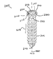
- the removable body extension assembly 2600 is a cylindrical shaped extension, which can be attached to a headless bone screw 2610 , bone screw 2100 , plate 1500 , or any other implantable implant requiring UDI tracking.
- the removable body extension assembly 2600 allows for indicia, or descriptive information 2710 , such as the part number 2714 and or serial/lot number 2716 , to be contained with the implant, specifically, when the surface area, like the shaft 2616 of screw 2610 , is not large enough to contain the descriptive information 2710 .
- the removable body extension assembly 2600 has an engagement end 2810 specifically designed to interface with an implant.
- the engagement extension 2810 is threaded to engage recess 3212 in the proximal head 2630 of a headless compression bone screw 2610 .
- the engagement extension 2810 can be press fit or have an interference fit engagement recess 3212 or head recess 3210 of the implant.
- the engagement extension 2810 may also be manufactured directly as part of the implant in a monolithic configuration and disengage through breaking connection located at the engagement extension end 2810 .
- the removable body extension 2600 Prior to inserting headless compression screw 2610 , the removable body extension 2900 is used to remove the screw from a screw caddie (not shown). The removable body extension 2900 is then removed by unscrewing the engagement section 2810 from the engagement recess 3212 of screw 2610 . Screw 2610 is then inserted into the patient. The removable body extension 2900 is left outside of the patient and the descriptive information 2710 is recorded.
- FIG. 30 shows an example of a plate 1500 with the removable body extension 2900 attached via the engagement extension 2810 .
- the removable body extension 2900 can be attached to a number of implants, such as the interbody spacer 100 , plate 1500 , headless compression screw 2610 , bone staple (not shown), suture anchor (not shown), or any other implant which is too small to physically laser mark descriptive information 2710 .
- headless compression screw 2610 is shown in more detail.
- the headless compression screw 2610 is defined by proximal head 2630 and a distal end 2640 joined by a shaft 2616 .
- the distal end 2640 has distal threads 2612 with a distal pitch 3310 and the proximal head 2630 has proximal threads 2614 with a proximal thread pitch 3312 , where the proximal thread pitch 3312 is less than distal thread pitch 3310 .
- the difference in proximal thread pitch 3312 and distal thread pitch 3310 causes a compressive force to generate between segments.
- the proximal head 2630 has an engagement recess 3210 which can be a Torx, Hexagonal, Square, or Phillips in shape.
- FIGS. 36-38 specifically show the self-cutting features of the headless bone screw 2620 .
- the proximal head 2630 has a groove 3620 , which removes material as the proximal head 2630 and the proximal threads 2614 begin to engage a substrate, such as bone.
- FIG. 37 illustrates a reverse cutting groove 3720 positioned on the distal end 2640 and engages the distal threads 2612 near the shaft 2616 .
- the reverse cutting groove 3720 removes material, such as bone, as the headless bone screw 2610 is removed.
- FIG. 38 illustrates the tip of the distal end 2640 , which includes distal threads 2612 and self drilling groove 3820 .
- the length of self-drilling groove 3820 is greater than the distal thread pitch 3310 and is used as the headless bone screw 2610 is inserted into a substrate such as bone.
- each device described above that is to be implanted i.e., interbody, screws, plate, etc.
- an antimicrobial agent such as, for example, silver oxide.
- the anti-microbial coating can be in the form of a nano coating or other type of coating. Such an antimicrobial coating can be used to reduce or eliminate infections within the patient.
Landscapes
- Health & Medical Sciences (AREA)
- Orthopedic Medicine & Surgery (AREA)
- Engineering & Computer Science (AREA)
- Biomedical Technology (AREA)
- Life Sciences & Earth Sciences (AREA)
- Neurology (AREA)
- Surgery (AREA)
- General Health & Medical Sciences (AREA)
- Veterinary Medicine (AREA)
- Heart & Thoracic Surgery (AREA)
- Public Health (AREA)
- Animal Behavior & Ethology (AREA)
- Nuclear Medicine, Radiotherapy & Molecular Imaging (AREA)
- Medical Informatics (AREA)
- Molecular Biology (AREA)
- Transplantation (AREA)
- Oral & Maxillofacial Surgery (AREA)
- Vascular Medicine (AREA)
- Cardiology (AREA)
- Physical Education & Sports Medicine (AREA)
- Pathology (AREA)
- Prostheses (AREA)
Abstract
Description
Claims (19)
Priority Applications (18)
| Application Number | Priority Date | Filing Date | Title |
|---|---|---|---|
| US14/054,100 US9387087B2 (en) | 2012-10-19 | 2013-10-15 | Orthopedic systems for spine and tracking control |
| PCT/US2014/060338 WO2015057604A1 (en) | 2012-10-19 | 2014-10-14 | Wedge osteotomy device and method of use |
| US14/513,300 US10864081B2 (en) | 2012-10-19 | 2014-10-14 | Wedge osteotomy device and method of use |
| US14/948,322 US10201433B2 (en) | 2012-10-19 | 2015-11-22 | System and method for correcting scoliosis |
| US15/162,657 US10369251B2 (en) | 2012-10-19 | 2016-05-24 | Anti-microbial and osteointegration nanotextured surfaces |
| US15/213,935 US10058431B2 (en) | 2012-10-19 | 2016-07-19 | Small joint fixation |
| US15/646,497 US10383737B2 (en) | 2012-10-19 | 2017-07-11 | Anatomical wedge implant |
| US16/049,854 US10639163B2 (en) | 2012-10-19 | 2018-07-31 | Small joint fixation |
| US16/201,144 US10888365B2 (en) | 2012-10-19 | 2018-11-27 | Lapidus screw guide assembly and method of insertion |
| US16/503,738 US11413371B2 (en) | 2013-10-15 | 2019-07-05 | System and method for correcting scoliosis |
| US16/504,405 US11547569B2 (en) | 2012-10-19 | 2019-07-08 | Anatomical wedge implant |
| US16/506,144 US11285241B2 (en) | 2012-10-19 | 2019-07-09 | Anti-microbial and osteointegration nanotextured surfaces |
| US16/527,185 US11147680B2 (en) | 2012-10-19 | 2019-07-31 | Small joint fixation |
| US17/108,168 US11389221B2 (en) | 2012-10-19 | 2020-12-01 | Lapidus screw guide assembly and method of insertion |
| US17/495,895 US11744709B2 (en) | 2012-10-19 | 2021-10-07 | Small joint fixation |
| US17/829,429 US12144531B2 (en) | 2012-10-19 | 2022-06-01 | Lapidus screw guide assembly and method of insertion |
| US18/229,883 US20230380982A1 (en) | 2012-10-19 | 2023-08-03 | Small Joint Fixation |
| US18/935,917 US20250057575A1 (en) | 2012-10-19 | 2024-11-04 | Beveled Screw |
Applications Claiming Priority (2)
| Application Number | Priority Date | Filing Date | Title |
|---|---|---|---|
| US201261715891P | 2012-10-19 | 2012-10-19 | |
| US14/054,100 US9387087B2 (en) | 2012-10-19 | 2013-10-15 | Orthopedic systems for spine and tracking control |
Related Child Applications (1)
| Application Number | Title | Priority Date | Filing Date |
|---|---|---|---|
| US14/513,300 Continuation-In-Part US10864081B2 (en) | 2012-10-19 | 2014-10-14 | Wedge osteotomy device and method of use |
Publications (2)
| Publication Number | Publication Date |
|---|---|
| US20140114415A1 US20140114415A1 (en) | 2014-04-24 |
| US9387087B2 true US9387087B2 (en) | 2016-07-12 |
Family
ID=50486039
Family Applications (1)
| Application Number | Title | Priority Date | Filing Date |
|---|---|---|---|
| US14/054,100 Active 2034-08-11 US9387087B2 (en) | 2012-10-19 | 2013-10-15 | Orthopedic systems for spine and tracking control |
Country Status (1)
| Country | Link |
|---|---|
| US (1) | US9387087B2 (en) |
Cited By (37)
| Publication number | Priority date | Publication date | Assignee | Title |
|---|---|---|---|---|
| US20170049579A1 (en) * | 2015-08-19 | 2017-02-23 | Raymond J. Quinlan | Spinal Fusion Device And Method Of Using Same |
| US9724207B2 (en) | 2003-02-14 | 2017-08-08 | DePuy Synthes Products, Inc. | In-situ formed intervertebral fusion device and method |
| US9949769B2 (en) | 2004-03-06 | 2018-04-24 | DePuy Synthes Products, Inc. | Dynamized interspinal implant |
| US10034776B1 (en) * | 2011-03-01 | 2018-07-31 | John W. McClellan | Peripheral vertebral body spacer implant and insertion tool |
| US10433974B2 (en) | 2003-06-30 | 2019-10-08 | DePuy Synthes Products, Inc. | Intervertebral implant with conformable endplate |
| US10537666B2 (en) | 2015-05-18 | 2020-01-21 | Stryker European Holdings I, Llc | Partially resorbable implants and methods |
| US10603182B2 (en) | 2015-01-14 | 2020-03-31 | Stryker European Holdings I, Llc | Spinal implant with fluid delivery capabilities |
| US20200282105A1 (en) * | 2013-03-15 | 2020-09-10 | Beacon Biomedical, Llc | Spinal implants with bioactive glass markers |
| US10835388B2 (en) | 2017-09-20 | 2020-11-17 | Stryker European Operations Holdings Llc | Spinal implants |
| US10888433B2 (en) | 2016-12-14 | 2021-01-12 | DePuy Synthes Products, Inc. | Intervertebral implant inserter and related methods |
| US10940016B2 (en) | 2017-07-05 | 2021-03-09 | Medos International Sarl | Expandable intervertebral fusion cage |
| US10966840B2 (en) | 2010-06-24 | 2021-04-06 | DePuy Synthes Products, Inc. | Enhanced cage insertion assembly |
| US10973652B2 (en) | 2007-06-26 | 2021-04-13 | DePuy Synthes Products, Inc. | Highly lordosed fusion cage |
| US11000386B2 (en) | 2015-01-14 | 2021-05-11 | Stryker European Holdings I, Llc | Spinal implant with porous and solid surfaces |
| US11026726B2 (en) | 2012-06-29 | 2021-06-08 | K2M, Inc. | Minimal-profile anterior cervical plate and cage apparatus and method of using same |
| US11273050B2 (en) | 2006-12-07 | 2022-03-15 | DePuy Synthes Products, Inc. | Intervertebral implant |
| US11344424B2 (en) | 2017-06-14 | 2022-05-31 | Medos International Sarl | Expandable intervertebral implant and related methods |
| US11426290B2 (en) | 2015-03-06 | 2022-08-30 | DePuy Synthes Products, Inc. | Expandable intervertebral implant, system, kit and method |
| US11426286B2 (en) | 2020-03-06 | 2022-08-30 | Eit Emerging Implant Technologies Gmbh | Expandable intervertebral implant |
| US11446155B2 (en) | 2017-05-08 | 2022-09-20 | Medos International Sarl | Expandable cage |
| US11446156B2 (en) | 2018-10-25 | 2022-09-20 | Medos International Sarl | Expandable intervertebral implant, inserter instrument, and related methods |
| US11452607B2 (en) | 2010-10-11 | 2022-09-27 | DePuy Synthes Products, Inc. | Expandable interspinous process spacer implant |
| US11497619B2 (en) | 2013-03-07 | 2022-11-15 | DePuy Synthes Products, Inc. | Intervertebral implant |
| US11510788B2 (en) | 2016-06-28 | 2022-11-29 | Eit Emerging Implant Technologies Gmbh | Expandable, angularly adjustable intervertebral cages |
| US11596523B2 (en) | 2016-06-28 | 2023-03-07 | Eit Emerging Implant Technologies Gmbh | Expandable and angularly adjustable articulating intervertebral cages |
| US11602438B2 (en) | 2008-04-05 | 2023-03-14 | DePuy Synthes Products, Inc. | Expandable intervertebral implant |
| US11607321B2 (en) | 2009-12-10 | 2023-03-21 | DePuy Synthes Products, Inc. | Bellows-like expandable interbody fusion cage |
| US11612491B2 (en) | 2009-03-30 | 2023-03-28 | DePuy Synthes Products, Inc. | Zero profile spinal fusion cage |
| US11654033B2 (en) | 2010-06-29 | 2023-05-23 | DePuy Synthes Products, Inc. | Distractible intervertebral implant |
| US11737881B2 (en) | 2008-01-17 | 2023-08-29 | DePuy Synthes Products, Inc. | Expandable intervertebral implant and associated method of manufacturing the same |
| US11744619B2 (en) | 2018-04-06 | 2023-09-05 | K2M, Inc. | Faceted bone plate |
| US11752009B2 (en) | 2021-04-06 | 2023-09-12 | Medos International Sarl | Expandable intervertebral fusion cage |
| US11850160B2 (en) | 2021-03-26 | 2023-12-26 | Medos International Sarl | Expandable lordotic intervertebral fusion cage |
| US11911287B2 (en) | 2010-06-24 | 2024-02-27 | DePuy Synthes Products, Inc. | Lateral spondylolisthesis reduction cage |
| USRE49973E1 (en) | 2013-02-28 | 2024-05-21 | DePuy Synthes Products, Inc. | Expandable intervertebral implant, system, kit and method |
| US12090064B2 (en) | 2022-03-01 | 2024-09-17 | Medos International Sarl | Stabilization members for expandable intervertebral implants, and related systems and methods |
| US12458406B2 (en) | 2020-04-09 | 2025-11-04 | Wright Medical Technology, Inc. | Jigs, systems, and methods for correcting joint deformities |
Families Citing this family (50)
| Publication number | Priority date | Publication date | Assignee | Title |
|---|---|---|---|---|
| US11395626B2 (en) | 2006-12-07 | 2022-07-26 | DePuy Synthes Products, Inc. | Sensor for intervertebral fusion indicia |
| US9039768B2 (en) | 2006-12-22 | 2015-05-26 | Medos International Sarl | Composite vertebral spacers and instrument |
| US20080161929A1 (en) | 2006-12-29 | 2008-07-03 | Mccormack Bruce | Cervical distraction device |
| WO2009089367A2 (en) | 2008-01-09 | 2009-07-16 | Providence Medical Technology, Inc. | Methods and apparatus for accessing and treating the facet joint |
| US20090248092A1 (en) | 2008-03-26 | 2009-10-01 | Jonathan Bellas | Posterior Intervertebral Disc Inserter and Expansion Techniques |
| US8267966B2 (en) | 2008-06-06 | 2012-09-18 | Providence Medical Technology, Inc. | Facet joint implants and delivery tools |
| US8361152B2 (en) | 2008-06-06 | 2013-01-29 | Providence Medical Technology, Inc. | Facet joint implants and delivery tools |
| WO2009148619A2 (en) | 2008-06-06 | 2009-12-10 | Providence Medical Technology, Inc. | Facet joint implants and delivery tools |
| US11224521B2 (en) | 2008-06-06 | 2022-01-18 | Providence Medical Technology, Inc. | Cervical distraction/implant delivery device |
| US8821555B2 (en) | 2009-02-11 | 2014-09-02 | Howmedica Osteonics Corp. | Intervertebral implant with integrated fixation |
| WO2014015309A1 (en) | 2012-07-20 | 2014-01-23 | Jcbd, Llc | Orthopedic anchoring system and methods |
| US9333090B2 (en) | 2010-01-13 | 2016-05-10 | Jcbd, Llc | Systems for and methods of fusing a sacroiliac joint |
| US9381045B2 (en) | 2010-01-13 | 2016-07-05 | Jcbd, Llc | Sacroiliac joint implant and sacroiliac joint instrument for fusing a sacroiliac joint |
| US9421109B2 (en) | 2010-01-13 | 2016-08-23 | Jcbd, Llc | Systems and methods of fusing a sacroiliac joint |
| US11529241B2 (en) | 2010-09-23 | 2022-12-20 | DePuy Synthes Products, Inc. | Fusion cage with in-line single piece fixation |
| US20120078373A1 (en) | 2010-09-23 | 2012-03-29 | Thomas Gamache | Stand alone intervertebral fusion device |
| US20120078372A1 (en) | 2010-09-23 | 2012-03-29 | Thomas Gamache | Novel implant inserter having a laterally-extending dovetail engagement feature |
| US9248028B2 (en) | 2011-09-16 | 2016-02-02 | DePuy Synthes Products, Inc. | Removable, bone-securing cover plate for intervertebral fusion cage |
| US9370435B2 (en) * | 2011-11-17 | 2016-06-21 | Zimmer Biomet Spine, Inc. | Modular anchor bone fusion cage |
| US9271836B2 (en) * | 2012-03-06 | 2016-03-01 | DePuy Synthes Products, Inc. | Nubbed plate |
| US10058431B2 (en) | 2012-10-19 | 2018-08-28 | Tyber Medical, LLC | Small joint fixation |
| US10182921B2 (en) | 2012-11-09 | 2019-01-22 | DePuy Synthes Products, Inc. | Interbody device with opening to allow packing graft and other biologics |
| WO2014146018A1 (en) | 2013-03-15 | 2014-09-18 | Jcbd, Llc | Systems and methods for fusing a sacroiliac joint and anchoring an orthopedic appliance |
| US9700356B2 (en) | 2013-07-30 | 2017-07-11 | Jcbd, Llc | Systems for and methods of fusing a sacroiliac joint |
| US10245087B2 (en) | 2013-03-15 | 2019-04-02 | Jcbd, Llc | Systems and methods for fusing a sacroiliac joint and anchoring an orthopedic appliance |
| US9826986B2 (en) | 2013-07-30 | 2017-11-28 | Jcbd, Llc | Systems for and methods of preparing a sacroiliac joint for fusion |
| US9717539B2 (en) | 2013-07-30 | 2017-08-01 | Jcbd, Llc | Implants, systems, and methods for fusing a sacroiliac joint |
| US9180022B2 (en) * | 2013-06-28 | 2015-11-10 | DePuy Synthes Products, Inc. | Spinal alignment clip |
| US10226353B2 (en) * | 2013-10-07 | 2019-03-12 | Warsaw Orthopedic, Inc. | Spinal implant system and method |
| US9283091B2 (en) * | 2013-10-07 | 2016-03-15 | Warsaw Orthopedic, Inc. | Spinal implant system and method |
| AU2015267055B2 (en) * | 2014-05-27 | 2020-04-02 | Christopher U. Phan | Lateral mass fixation implant |
| US9801546B2 (en) | 2014-05-27 | 2017-10-31 | Jcbd, Llc | Systems for and methods of diagnosing and treating a sacroiliac joint disorder |
| US10206720B2 (en) * | 2014-09-03 | 2019-02-19 | Aesculap Implant Systems, Llc | Fastener, spinal interbody system including same and method |
| US10383733B2 (en) | 2014-10-22 | 2019-08-20 | Biomet C.V. | Method and apparatus for bone fixation |
| CN107205825A (en) * | 2014-12-16 | 2017-09-26 | 陶瓷技术有限责任公司 | Vertebra Invasive lumbar fusion device and its insertion instrument |
| WO2018081313A1 (en) * | 2016-10-25 | 2018-05-03 | Elevation Spine, Inc. | Intervertebral implant and method of use |
| WO2018213779A1 (en) | 2017-05-19 | 2018-11-22 | Providence Medical Technology, Inc. | Spinal fixation access and delivery system |
| US10624760B2 (en) | 2017-05-22 | 2020-04-21 | Warsaw Orthopedic, Inc. | Spinal implant system and method |
| US10603055B2 (en) | 2017-09-15 | 2020-03-31 | Jcbd, Llc | Systems for and methods of preparing and fusing a sacroiliac joint |
| WO2019136263A1 (en) | 2018-01-04 | 2019-07-11 | Providence Medical Technology, Inc. | Facet screw and delivery device |
| PL425339A1 (en) * | 2018-04-24 | 2019-11-04 | Radomskie Centrum Innowacji I Tech Spolka Z Ograniczona Odpowiedzialnoscia | Interference screw and method for producing it |
| AU2019213392B2 (en) | 2018-08-09 | 2024-11-28 | Vb Spine Us Opco Llc | Interbody implants and optimization features thereof |
| US12144513B2 (en) | 2018-09-21 | 2024-11-19 | Providence Medical Technology, Inc. | Vertebral joint access and decortication devices and methods of using |
| US20200281736A1 (en) * | 2019-03-04 | 2020-09-10 | K2M, Inc. | Intervertebral Implant Assembly and Instruments Therefor |
| USD945621S1 (en) | 2020-02-27 | 2022-03-08 | Providence Medical Technology, Inc. | Spinal cage |
| US11998457B2 (en) * | 2020-05-05 | 2024-06-04 | Corelink, Llc | Implant trial with radiographically visible indicium |
| WO2021231329A1 (en) | 2020-05-11 | 2021-11-18 | Gensano Llc | Cannulated bone implant |
| USD1098431S1 (en) | 2023-02-27 | 2025-10-14 | Providence Medical Technology, Inc. | Spinal cage |
| US20240299176A1 (en) * | 2023-03-08 | 2024-09-12 | Nuvasive, Inc. | Anchoring nails and systems |
| USD1098433S1 (en) | 2023-12-28 | 2025-10-14 | Providence Medical Technology, Inc. | Spinal cage |
Citations (20)
| Publication number | Priority date | Publication date | Assignee | Title |
|---|---|---|---|---|
| US5888227A (en) * | 1995-10-20 | 1999-03-30 | Synthes (U.S.A.) | Inter-vertebral implant |
| US6261291B1 (en) * | 1999-07-08 | 2001-07-17 | David J. Talaber | Orthopedic implant assembly |
| US6306170B2 (en) * | 1997-04-25 | 2001-10-23 | Tegementa, L.L.C. | Threaded fusion cage anchoring device and method |
| US20050101960A1 (en) | 2001-04-03 | 2005-05-12 | Vincent Fiere | Stabilised interbody fusion system for vertebrae |
| US6964687B1 (en) * | 1999-07-09 | 2005-11-15 | Scient'x | Anatomical interbody implant and gripper for same |
| US7166129B2 (en) * | 1999-12-08 | 2007-01-23 | Warsaw Orthopedic, Inc. | Method for forming a spinal implant surface configuration |
| US7238203B2 (en) * | 2001-12-12 | 2007-07-03 | Vita Special Purpose Corporation | Bioactive spinal implants and method of manufacture thereof |
| WO2007098288A2 (en) * | 2006-02-27 | 2007-08-30 | Synthes (U.S.A.) | Intervertebral implant with fixation geometry |
| US20080230421A1 (en) * | 2007-02-28 | 2008-09-25 | Aesculap Ag & Co. Kg | Surgical data carrier |
| US20080243135A1 (en) * | 2007-03-30 | 2008-10-02 | Robinson Randolph C | Driver-Fixator System, Method, and Apparatus |
| US7491237B2 (en) * | 2004-03-26 | 2009-02-17 | Synthes Usa, Llc | Allograft implant |
| US20090182430A1 (en) | 2008-01-16 | 2009-07-16 | Aesculap Implant Systems, Inc. | Dynamic interbody |
| US20090204214A1 (en) * | 2008-02-07 | 2009-08-13 | Showa Ika Kohgyo Co., Ltd. | Cage |
| US7641690B2 (en) * | 2004-08-23 | 2010-01-05 | Abdou M Samy | Bone fixation and fusion device |
| US20110106171A1 (en) * | 2009-11-04 | 2011-05-05 | X-Spine Systems, Inc. | Screw implant and system and method for locking a screw in an implant plate |
| US20110172780A1 (en) * | 2009-12-31 | 2011-07-14 | John Scheland | Method and apparatus for fusing the bones of a joint |
| US20110224734A1 (en) * | 2009-10-28 | 2011-09-15 | Orthopro Llc | Compression plate kit and methods for repairing bone discontinuities |
| US8216312B2 (en) | 2007-05-31 | 2012-07-10 | Zimmer Spine, Inc. | Spinal interbody system and method |
| US20130238095A1 (en) | 2012-03-06 | 2013-09-12 | Nicholas Pavento | Nubbed Plate |
| US20130268080A1 (en) | 2010-08-11 | 2013-10-10 | Warsaw Orthopedic, Inc. | Interbody spinal implants with extravertebral support plates |
-
2013
- 2013-10-15 US US14/054,100 patent/US9387087B2/en active Active
Patent Citations (20)
| Publication number | Priority date | Publication date | Assignee | Title |
|---|---|---|---|---|
| US5888227A (en) * | 1995-10-20 | 1999-03-30 | Synthes (U.S.A.) | Inter-vertebral implant |
| US6306170B2 (en) * | 1997-04-25 | 2001-10-23 | Tegementa, L.L.C. | Threaded fusion cage anchoring device and method |
| US6261291B1 (en) * | 1999-07-08 | 2001-07-17 | David J. Talaber | Orthopedic implant assembly |
| US6964687B1 (en) * | 1999-07-09 | 2005-11-15 | Scient'x | Anatomical interbody implant and gripper for same |
| US7166129B2 (en) * | 1999-12-08 | 2007-01-23 | Warsaw Orthopedic, Inc. | Method for forming a spinal implant surface configuration |
| US20050101960A1 (en) | 2001-04-03 | 2005-05-12 | Vincent Fiere | Stabilised interbody fusion system for vertebrae |
| US7238203B2 (en) * | 2001-12-12 | 2007-07-03 | Vita Special Purpose Corporation | Bioactive spinal implants and method of manufacture thereof |
| US7491237B2 (en) * | 2004-03-26 | 2009-02-17 | Synthes Usa, Llc | Allograft implant |
| US7641690B2 (en) * | 2004-08-23 | 2010-01-05 | Abdou M Samy | Bone fixation and fusion device |
| WO2007098288A2 (en) * | 2006-02-27 | 2007-08-30 | Synthes (U.S.A.) | Intervertebral implant with fixation geometry |
| US20080230421A1 (en) * | 2007-02-28 | 2008-09-25 | Aesculap Ag & Co. Kg | Surgical data carrier |
| US20080243135A1 (en) * | 2007-03-30 | 2008-10-02 | Robinson Randolph C | Driver-Fixator System, Method, and Apparatus |
| US8216312B2 (en) | 2007-05-31 | 2012-07-10 | Zimmer Spine, Inc. | Spinal interbody system and method |
| US20090182430A1 (en) | 2008-01-16 | 2009-07-16 | Aesculap Implant Systems, Inc. | Dynamic interbody |
| US20090204214A1 (en) * | 2008-02-07 | 2009-08-13 | Showa Ika Kohgyo Co., Ltd. | Cage |
| US20110224734A1 (en) * | 2009-10-28 | 2011-09-15 | Orthopro Llc | Compression plate kit and methods for repairing bone discontinuities |
| US20110106171A1 (en) * | 2009-11-04 | 2011-05-05 | X-Spine Systems, Inc. | Screw implant and system and method for locking a screw in an implant plate |
| US20110172780A1 (en) * | 2009-12-31 | 2011-07-14 | John Scheland | Method and apparatus for fusing the bones of a joint |
| US20130268080A1 (en) | 2010-08-11 | 2013-10-10 | Warsaw Orthopedic, Inc. | Interbody spinal implants with extravertebral support plates |
| US20130238095A1 (en) | 2012-03-06 | 2013-09-12 | Nicholas Pavento | Nubbed Plate |
Non-Patent Citations (1)
| Title |
|---|
| International Search Report and Written Opinion for PCT/US2014/060338, mailed Jan. 19, 2015. 16 pages. |
Cited By (92)
| Publication number | Priority date | Publication date | Assignee | Title |
|---|---|---|---|---|
| US10405986B2 (en) | 2003-02-14 | 2019-09-10 | DePuy Synthes Products, Inc. | In-situ formed intervertebral fusion device and method |
| US10583013B2 (en) | 2003-02-14 | 2020-03-10 | DePuy Synthes Products, Inc. | In-situ formed intervertebral fusion device and method |
| US9788963B2 (en) | 2003-02-14 | 2017-10-17 | DePuy Synthes Products, Inc. | In-situ formed intervertebral fusion device and method |
| US9801729B2 (en) | 2003-02-14 | 2017-10-31 | DePuy Synthes Products, Inc. | In-situ formed intervertebral fusion device and method |
| US9808351B2 (en) | 2003-02-14 | 2017-11-07 | DePuy Synthes Products, Inc. | In-situ formed intervertebral fusion device and method |
| US9814590B2 (en) | 2003-02-14 | 2017-11-14 | DePuy Synthes Products, Inc. | In-situ formed intervertebral fusion device and method |
| US9814589B2 (en) | 2003-02-14 | 2017-11-14 | DePuy Synthes Products, Inc. | In-situ formed intervertebral fusion device and method |
| US9925060B2 (en) | 2003-02-14 | 2018-03-27 | DePuy Synthes Products, Inc. | In-situ formed intervertebral fusion device and method |
| US10639164B2 (en) | 2003-02-14 | 2020-05-05 | DePuy Synthes Products, Inc. | In-situ formed intervertebral fusion device and method |
| US11096794B2 (en) | 2003-02-14 | 2021-08-24 | DePuy Synthes Products, Inc. | In-situ formed intervertebral fusion device and method |
| US10085843B2 (en) | 2003-02-14 | 2018-10-02 | DePuy Synthes Products, Inc. | In-situ formed intervertebral fusion device and method |
| US10376372B2 (en) | 2003-02-14 | 2019-08-13 | DePuy Synthes Products, Inc. | In-situ formed intervertebral fusion device and method |
| US9724207B2 (en) | 2003-02-14 | 2017-08-08 | DePuy Synthes Products, Inc. | In-situ formed intervertebral fusion device and method |
| US10786361B2 (en) | 2003-02-14 | 2020-09-29 | DePuy Synthes Products, Inc. | In-situ formed intervertebral fusion device and method |
| US11207187B2 (en) | 2003-02-14 | 2021-12-28 | DePuy Synthes Products, Inc. | In-situ formed intervertebral fusion device and method |
| US10420651B2 (en) | 2003-02-14 | 2019-09-24 | DePuy Synthes Products, Inc. | In-situ formed intervertebral fusion device and method |
| US10433971B2 (en) | 2003-02-14 | 2019-10-08 | DePuy Synthes Products, Inc. | In-situ formed intervertebral fusion device and method |
| US10492918B2 (en) | 2003-02-14 | 2019-12-03 | DePuy Synthes Products, Inc. | In-situ formed intervertebral fusion device and method |
| US10575959B2 (en) | 2003-02-14 | 2020-03-03 | DePuy Synthes Products, Inc. | In-situ formed intervertebral fusion device and method |
| US11432938B2 (en) | 2003-02-14 | 2022-09-06 | DePuy Synthes Products, Inc. | In-situ intervertebral fusion device and method |
| US10555817B2 (en) | 2003-02-14 | 2020-02-11 | DePuy Synthes Products, Inc. | In-situ formed intervertebral fusion device and method |
| US10433974B2 (en) | 2003-06-30 | 2019-10-08 | DePuy Synthes Products, Inc. | Intervertebral implant with conformable endplate |
| US11612493B2 (en) | 2003-06-30 | 2023-03-28 | DePuy Synthes Products, Inc. | Intervertebral implant with conformable endplate |
| US10433881B2 (en) | 2004-03-06 | 2019-10-08 | DePuy Synthes Products, Inc. | Dynamized interspinal implant |
| US10512489B2 (en) | 2004-03-06 | 2019-12-24 | DePuy Synthes Products, Inc. | Dynamized interspinal implant |
| US9949769B2 (en) | 2004-03-06 | 2018-04-24 | DePuy Synthes Products, Inc. | Dynamized interspinal implant |
| US11712345B2 (en) | 2006-12-07 | 2023-08-01 | DePuy Synthes Products, Inc. | Intervertebral implant |
| US11273050B2 (en) | 2006-12-07 | 2022-03-15 | DePuy Synthes Products, Inc. | Intervertebral implant |
| US11642229B2 (en) | 2006-12-07 | 2023-05-09 | DePuy Synthes Products, Inc. | Intervertebral implant |
| US11660206B2 (en) | 2006-12-07 | 2023-05-30 | DePuy Synthes Products, Inc. | Intervertebral implant |
| US11497618B2 (en) | 2006-12-07 | 2022-11-15 | DePuy Synthes Products, Inc. | Intervertebral implant |
| US11432942B2 (en) | 2006-12-07 | 2022-09-06 | DePuy Synthes Products, Inc. | Intervertebral implant |
| US11622868B2 (en) | 2007-06-26 | 2023-04-11 | DePuy Synthes Products, Inc. | Highly lordosed fusion cage |
| US10973652B2 (en) | 2007-06-26 | 2021-04-13 | DePuy Synthes Products, Inc. | Highly lordosed fusion cage |
| US11737881B2 (en) | 2008-01-17 | 2023-08-29 | DePuy Synthes Products, Inc. | Expandable intervertebral implant and associated method of manufacturing the same |
| US12440346B2 (en) | 2008-04-05 | 2025-10-14 | DePuy Synthes Products, Inc. | Expandable intervertebral implant |
| US11701234B2 (en) | 2008-04-05 | 2023-07-18 | DePuy Synthes Products, Inc. | Expandable intervertebral implant |
| US12011361B2 (en) | 2008-04-05 | 2024-06-18 | DePuy Synthes Products, Inc. | Expandable intervertebral implant |
| US11617655B2 (en) | 2008-04-05 | 2023-04-04 | DePuy Synthes Products, Inc. | Expandable intervertebral implant |
| US12023255B2 (en) | 2008-04-05 | 2024-07-02 | DePuy Synthes Products, Inc. | Expandable inter vertebral implant |
| US11712342B2 (en) | 2008-04-05 | 2023-08-01 | DePuy Synthes Products, Inc. | Expandable intervertebral implant |
| US11602438B2 (en) | 2008-04-05 | 2023-03-14 | DePuy Synthes Products, Inc. | Expandable intervertebral implant |
| US11712341B2 (en) | 2008-04-05 | 2023-08-01 | DePuy Synthes Products, Inc. | Expandable intervertebral implant |
| US11707359B2 (en) | 2008-04-05 | 2023-07-25 | DePuy Synthes Products, Inc. | Expandable intervertebral implant |
| US12097124B2 (en) | 2009-03-30 | 2024-09-24 | DePuy Synthes Products, Inc. | Zero profile spinal fusion cage |
| US11612491B2 (en) | 2009-03-30 | 2023-03-28 | DePuy Synthes Products, Inc. | Zero profile spinal fusion cage |
| US11607321B2 (en) | 2009-12-10 | 2023-03-21 | DePuy Synthes Products, Inc. | Bellows-like expandable interbody fusion cage |
| US10966840B2 (en) | 2010-06-24 | 2021-04-06 | DePuy Synthes Products, Inc. | Enhanced cage insertion assembly |
| US11911287B2 (en) | 2010-06-24 | 2024-02-27 | DePuy Synthes Products, Inc. | Lateral spondylolisthesis reduction cage |
| US11872139B2 (en) | 2010-06-24 | 2024-01-16 | DePuy Synthes Products, Inc. | Enhanced cage insertion assembly |
| US11654033B2 (en) | 2010-06-29 | 2023-05-23 | DePuy Synthes Products, Inc. | Distractible intervertebral implant |
| US11452607B2 (en) | 2010-10-11 | 2022-09-27 | DePuy Synthes Products, Inc. | Expandable interspinous process spacer implant |
| US10874526B1 (en) * | 2011-03-01 | 2020-12-29 | John W. McClellan | Peripheral vertebral body spacer implant and insertion tool |
| US10034776B1 (en) * | 2011-03-01 | 2018-07-31 | John W. McClellan | Peripheral vertebral body spacer implant and insertion tool |
| US11026726B2 (en) | 2012-06-29 | 2021-06-08 | K2M, Inc. | Minimal-profile anterior cervical plate and cage apparatus and method of using same |
| USRE49973E1 (en) | 2013-02-28 | 2024-05-21 | DePuy Synthes Products, Inc. | Expandable intervertebral implant, system, kit and method |
| US11497619B2 (en) | 2013-03-07 | 2022-11-15 | DePuy Synthes Products, Inc. | Intervertebral implant |
| US11850164B2 (en) | 2013-03-07 | 2023-12-26 | DePuy Synthes Products, Inc. | Intervertebral implant |
| US20200282105A1 (en) * | 2013-03-15 | 2020-09-10 | Beacon Biomedical, Llc | Spinal implants with bioactive glass markers |
| US10603182B2 (en) | 2015-01-14 | 2020-03-31 | Stryker European Holdings I, Llc | Spinal implant with fluid delivery capabilities |
| US12268613B2 (en) | 2015-01-14 | 2025-04-08 | Stryker European Operations Holdings Llc | Spinal implant with porous and solid surfaces |
| US11000386B2 (en) | 2015-01-14 | 2021-05-11 | Stryker European Holdings I, Llc | Spinal implant with porous and solid surfaces |
| US11266510B2 (en) | 2015-01-14 | 2022-03-08 | Stryker European Operations Holdings Llc | Spinal implant with fluid delivery capabilities |
| US11426290B2 (en) | 2015-03-06 | 2022-08-30 | DePuy Synthes Products, Inc. | Expandable intervertebral implant, system, kit and method |
| US12263279B2 (en) | 2015-05-18 | 2025-04-01 | Stryker European Operations Holdings Llc | Partially resorbable implants and methods |
| US11623027B2 (en) | 2015-05-18 | 2023-04-11 | Stryker European Operations Holdings Llc | Partially resorbable implants and methods |
| US10537666B2 (en) | 2015-05-18 | 2020-01-21 | Stryker European Holdings I, Llc | Partially resorbable implants and methods |
| US20170049579A1 (en) * | 2015-08-19 | 2017-02-23 | Raymond J. Quinlan | Spinal Fusion Device And Method Of Using Same |
| US10610375B2 (en) * | 2015-08-19 | 2020-04-07 | Raymond J. Quinlan | Spinal fusion device and method of using same |
| US11510788B2 (en) | 2016-06-28 | 2022-11-29 | Eit Emerging Implant Technologies Gmbh | Expandable, angularly adjustable intervertebral cages |
| US12433757B2 (en) | 2016-06-28 | 2025-10-07 | Eit Emerging Implant Technologies Gmbh | Expandable, angularly adjustable and articulating intervertebral cages |
| US12390343B2 (en) | 2016-06-28 | 2025-08-19 | Eit Emerging Implant Technologies Gmbh | Expandable, angularly adjustable intervertebral cages |
| US11596523B2 (en) | 2016-06-28 | 2023-03-07 | Eit Emerging Implant Technologies Gmbh | Expandable and angularly adjustable articulating intervertebral cages |
| US11596522B2 (en) | 2016-06-28 | 2023-03-07 | Eit Emerging Implant Technologies Gmbh | Expandable and angularly adjustable intervertebral cages with articulating joint |
| US10888433B2 (en) | 2016-12-14 | 2021-01-12 | DePuy Synthes Products, Inc. | Intervertebral implant inserter and related methods |
| US12427031B2 (en) | 2017-05-08 | 2025-09-30 | Medos International Sarl | Expandable cage |
| US11446155B2 (en) | 2017-05-08 | 2022-09-20 | Medos International Sarl | Expandable cage |
| US11344424B2 (en) | 2017-06-14 | 2022-05-31 | Medos International Sarl | Expandable intervertebral implant and related methods |
| US10940016B2 (en) | 2017-07-05 | 2021-03-09 | Medos International Sarl | Expandable intervertebral fusion cage |
| US12133806B2 (en) | 2017-09-20 | 2024-11-05 | Stryker European Operations Holdings Llc | Spinal implants |
| US10835388B2 (en) | 2017-09-20 | 2020-11-17 | Stryker European Operations Holdings Llc | Spinal implants |
| US11622867B2 (en) | 2017-09-20 | 2023-04-11 | Stryker European Operations Holdings Llc | Spinal implants |
| US11744619B2 (en) | 2018-04-06 | 2023-09-05 | K2M, Inc. | Faceted bone plate |
| US11446156B2 (en) | 2018-10-25 | 2022-09-20 | Medos International Sarl | Expandable intervertebral implant, inserter instrument, and related methods |
| US11806245B2 (en) | 2020-03-06 | 2023-11-07 | Eit Emerging Implant Technologies Gmbh | Expandable intervertebral implant |
| US11426286B2 (en) | 2020-03-06 | 2022-08-30 | Eit Emerging Implant Technologies Gmbh | Expandable intervertebral implant |
| US12458406B2 (en) | 2020-04-09 | 2025-11-04 | Wright Medical Technology, Inc. | Jigs, systems, and methods for correcting joint deformities |
| US11850160B2 (en) | 2021-03-26 | 2023-12-26 | Medos International Sarl | Expandable lordotic intervertebral fusion cage |
| US12023258B2 (en) | 2021-04-06 | 2024-07-02 | Medos International Sarl | Expandable intervertebral fusion cage |
| US11752009B2 (en) | 2021-04-06 | 2023-09-12 | Medos International Sarl | Expandable intervertebral fusion cage |
| US12447026B2 (en) | 2021-04-06 | 2025-10-21 | Medos International Sarl | Expandable inter vertebral fusion cage |
| US12090064B2 (en) | 2022-03-01 | 2024-09-17 | Medos International Sarl | Stabilization members for expandable intervertebral implants, and related systems and methods |
Also Published As
| Publication number | Publication date |
|---|---|
| US20140114415A1 (en) | 2014-04-24 |
Similar Documents
| Publication | Publication Date | Title |
|---|---|---|
| US9387087B2 (en) | Orthopedic systems for spine and tracking control | |
| US10864081B2 (en) | Wedge osteotomy device and method of use | |
| US12102543B2 (en) | Inter vertebral implant | |
| EP3024418B1 (en) | Fusion plate with directional holes and implant systems employing the same | |
| US20210000608A1 (en) | Facet joint implant | |
| US10512547B2 (en) | Interbody spacer | |
| EP2779954B1 (en) | Modular anchor bone fusion cage | |
| US9629664B2 (en) | Anterior cervical plate | |
| US8425607B2 (en) | Anchor member locking features | |
| US10363144B2 (en) | Expandable spinal implant | |
| US20210338454A1 (en) | 3d printed osteogenesis scaffold | |
| US20060276793A1 (en) | Bone fixation plate with self-locking screws | |
| US20120158143A1 (en) | ALIF Spinal Cage | |
| US20100249937A1 (en) | Flanged interbody fusion device | |
| US20200282105A1 (en) | Spinal implants with bioactive glass markers | |
| US9855150B2 (en) | Interbody spacer | |
| WO2008116192A2 (en) | Spinal implants and methods of providing dynamic stability to the spine | |
| US20130218277A1 (en) | Interbody fusion device | |
| US20200093610A1 (en) | Spinal Implant | |
| US11278420B2 (en) | Recessed pocket spinal implant |
Legal Events
| Date | Code | Title | Description |
|---|---|---|---|
| AS | Assignment |
Owner name: TYBER MEDICAL LLC, NEW JERSEY Free format text: ASSIGNMENT OF ASSIGNORS INTEREST;ASSIGNOR:TYBER, JEFFREY;REEL/FRAME:031458/0246 Effective date: 20131022 |
|
| STCF | Information on status: patent grant |
Free format text: PATENTED CASE |
|
| MAFP | Maintenance fee payment |
Free format text: PAYMENT OF MAINTENANCE FEE, 4TH YR, SMALL ENTITY (ORIGINAL EVENT CODE: M2551); ENTITY STATUS OF PATENT OWNER: SMALL ENTITY Year of fee payment: 4 |
|
| MAFP | Maintenance fee payment |
Free format text: PAYMENT OF MAINTENANCE FEE, 8TH YR, SMALL ENTITY (ORIGINAL EVENT CODE: M2552); ENTITY STATUS OF PATENT OWNER: SMALL ENTITY Year of fee payment: 8 |
|
| AS | Assignment |
Owner name: OHA AGENCY LLC, AS COLLATERAL AGENT, NEW YORK Free format text: SECURITY INTEREST;ASSIGNORS:PIONEER SURGICAL TECHNOLOGY, INC.;TYBER MEDICAL LLC;SMADE SAS;AND OTHERS;REEL/FRAME:071575/0563 Effective date: 20250612 |