US938479A - Head-adjusting mechanism. - Google Patents
Head-adjusting mechanism. Download PDFInfo
- Publication number
- US938479A US938479A US46775808A US1908467758A US938479A US 938479 A US938479 A US 938479A US 46775808 A US46775808 A US 46775808A US 1908467758 A US1908467758 A US 1908467758A US 938479 A US938479 A US 938479A
- Authority
- US
- United States
- Prior art keywords
- gear
- head
- worm
- rocker
- mesh
- Prior art date
- Legal status (The legal status is an assumption and is not a legal conclusion. Google has not performed a legal analysis and makes no representation as to the accuracy of the status listed.)
- Expired - Lifetime
Links
Images

Classifications
-
- F—MECHANICAL ENGINEERING; LIGHTING; HEATING; WEAPONS; BLASTING
- F16—ENGINEERING ELEMENTS AND UNITS; GENERAL MEASURES FOR PRODUCING AND MAINTAINING EFFECTIVE FUNCTIONING OF MACHINES OR INSTALLATIONS; THERMAL INSULATION IN GENERAL
- F16H—GEARING
- F16H3/00—Toothed gearings for conveying rotary motion with variable gear ratio or for reversing rotary motion
- F16H3/02—Toothed gearings for conveying rotary motion with variable gear ratio or for reversing rotary motion without gears having orbital motion
- F16H3/20—Toothed gearings for conveying rotary motion with variable gear ratio or for reversing rotary motion without gears having orbital motion exclusively or essentially using gears that can be moved out of gear
- F16H3/36—Toothed gearings for conveying rotary motion with variable gear ratio or for reversing rotary motion without gears having orbital motion exclusively or essentially using gears that can be moved out of gear with a single gear meshable with any of a set of coaxial gears of different diameters
- F16H3/363—Toothed gearings for conveying rotary motion with variable gear ratio or for reversing rotary motion without gears having orbital motion exclusively or essentially using gears that can be moved out of gear with a single gear meshable with any of a set of coaxial gears of different diameters the teeth of the set of coaxial gears being arranged on a surface of generally conical shape
-
- Y—GENERAL TAGGING OF NEW TECHNOLOGICAL DEVELOPMENTS; GENERAL TAGGING OF CROSS-SECTIONAL TECHNOLOGIES SPANNING OVER SEVERAL SECTIONS OF THE IPC; TECHNICAL SUBJECTS COVERED BY FORMER USPC CROSS-REFERENCE ART COLLECTIONS [XRACs] AND DIGESTS
- Y10—TECHNICAL SUBJECTS COVERED BY FORMER USPC
- Y10T—TECHNICAL SUBJECTS COVERED BY FORMER US CLASSIFICATION
- Y10T74/00—Machine element or mechanism
- Y10T74/19—Gearing
- Y10T74/19219—Interchangeably locked
- Y10T74/19293—Longitudinally slidable
- Y10T74/19298—Multiple spur gears
- Y10T74/19302—Multiple spur gears with tumbler gear
Definitions
- This invention relates to head-adjusting mechanism, the object of the invention being to provide simple and effective means of the kind set forth for obtaining coarse and fine adjustments of a head in a ready, quick and accurate manner.
- Head adjusting mechanism comprising my invention can be employed with advantage in many difierent connections; for example it might form part of a grinding machine, a metal-working or a wood-working machine, these being three of the ways in which said mechanism may be utilized.
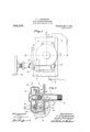
- Figure 1 is a side elevation of head adjusting mechanism embodying my invention
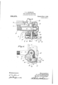
- Fig. 2 is a vertical section on the line 22 of Fig. 1.
- Figs. 3 and l are horizontal and vertical sections on the lines 3-8 and 4-4 respectively of said Fig. 1.
- Fig. 5 is a top plan view of a rocker and certain adjunctive devices
- Figs. 6 and 7 are diagrammatic views of gearing showing the elements differently related in said two figures.
- the head which is adjustable in accordance with my invention will vary in construction and direction of operation to conform to the necessities of the particular type of machine in which it may be incorporated.
- the head might move vertically as does that illustrated in the drawings or it might move horizontally or even at an angle to either the vertical or horizontal.
- the head shown in the drawings is denoted in a general way by 2 and it is adapted to slide along suitable ways upon a column as 8. These two features are common in various kinds of grinding and metal working machines for which reason it is not necessary to describe the same in detail. Said head might support a grinding or milling tool while 011 the other hand it might support the work, these simply being mentioned as uses to which said head can be put in practice.
- As a simple means for moving the head I may employ rack and pinion means the rack being preferably fastened to the column 3 while the pinion is mounted on the head 2 for movement therewith.
- the rack is denoted by at and is fastened in some suitable manner to the column as is common in various arts, the cooperating pinion being designated by 5.
- Said pinion is shown as fastened to a short rotary shaft 6 supported by an elongated hub or sleeve as 7 projecting from the flange or plate 8 forming part of the casing or housing 9 which incloses the several elements of the adjusting mechanism.
- This flange 8 can be bolted or otherwise secured to the head 2.
- the casing 9 presents a suitable device for inclosing and protecting the several elements of the adjusting mechanism; other means might be employed for this purpose if desired.
- the casing however, with its inclosed parts presents an article of manufacture which can be attached in its entirety to existing types of grinding and metal-working machines.
- a hub or sleeve 10 On the inner side of the flange 8 there is shown a hub or sleeve 10 a prolongation or continnation of the hub or sleeve 7 the pinion shaft 6 extending entirely through these two hubs and into the interior of the casing or housing 9.
- a gear 11 which in the present lnstance is of compound constructlon, 1t comprising a peripheral Wormportion 12 and a lateral or face bevel-tooth portion 13 the two portions of said gear cooperating with different gears as will hereinafter appear.
- a second shaft represented as sustained jointly by the casing 9 and a bearing on the hub 10,
- a bevel gear 15 in mesh at all times with the bevel tooth portion 13 of the gear 11.
- a pinion 16' is shown as keyed onto the hub of said bevel gear 15.
- the pinion or gear 16 is cooperative with a pinion or gear as 17 although these two members are not constantly in mesh as will hereinafter appear.
- the gear 17 is supported by a stud shaft 18 mounted at one side of the axis of oscillation of a suitable rocker such as that denoted in a general way by 19 and which constitutes a convenient carrier for said gear 17.
- a shaft as 20 presents a desirable support for said rocker 19.
- the shaft 20 is shown as extending from front to rear of the casing or housing 9 and is supported by suitable bearings on the latter. Said shaft is equipped with a suitable device by which it can be easily turned by an operator and the hand-wheel 21 serves conveniently for this purpose.
- To the shaft 20 I have shown as fastened a pinion 22 in mesh at all times with the gear 17 and similarly related with a gear as 23 supported by said rocker 19 although it is directly sustained by a shaft as 24 mounted on said rocker for rotation on the side thereof opposite that on which the gear 17 is located.
- the rocker 19 is shown as being of pan or basin-shape and the three gears 17, 22 and 28 rotate in said pan or basin like rocker.
- the said rocker owing to its shape may be used as a guard for said three gears, to catch grease or drippings therefrom or if necessary to contain a lubricant, and for compactness it may be set in the casing or housing 9.
- the shaft 24 to which I have referred is supported by the opposite sides of lateral walls of said basin like rocker and in addition to having the gear 23 fastened thereto is equipped with a rigid worm 25 adapted to mesh with the worm-tooth or circumferential portion of the gear 11.
- rocker 19 is positively locked in position to maintain the gear 17 in mesh with the gear 16, and I illustrate and will hereinafter describe means for securing this result. It will be further assumed that the rough or primary adjust ment has been obtained and that it is necessary to make a precisionized or final adjustment. To accomplish this, the rocker 19 is manipulated to effect the movement of the gear 17 out of mesh wit-h the gear 16 and the mesh of the worm 25 with the worm portion 12 of the gear 11. When this result is accomplished the rocker will be held in its shifted position as will hereinafter appear.
- the rocker 19 is represented as provided at its outer end with a spring-plunger 26 adapted to enter either of two holes or .perforations as 27 and 28 in the adjacent portion of the casing 9.-
- the plunger or stop pin 26 is shown in Fig. 4 as seated in the lower opening 27 thereby locking the rocker 19 rigidly in position to hold the gear 17 in mesh with the gear 16 to accomplish the primary adjustment of the head 2.
- the plunger 26 is withdrawn from said lower opening 27 and the rocker is then swung to carry the gear 17 out of mesh with the gear 16 and the worm 25 into mesh with the worm-portion 12 and when this occurs the power of the spring of said plunger thrusts the same into the opening 28 to lock the said rocker in its second adjusted position.
- an adjustable head comprising a gear having bevel tooth and worm-tooth portions, bevel and worm gears cooperative with the respective bevel and worm tooth portions, and means for operating said bevel and worm gears to give to the head different degrees of movement.
- an adjustable head comprising a gear having bevel and worm portions, a bevel gear in mesh with the bevel portion of said first mentioned gear, a worm gear movable into and out of mesh with the worm portion of said first mentioned gear, and means whereby said bevel gear can be turned simultaneously with the movement of said worm-gear out of mesh with the worm portion of said first mentioned gear or whereby said bevel gear can be thrown out of action when said worm gear is in mesh with said worm portion.
- an adjustable head and means for moving said head comprising a gear having bevel and worm portions, a bevel gear constantly in mesh with said bevel portion, a third gear for rotating said bevel gear, a rocker and a fourth gear and a worm gear on said rocker the latter on its oscillation serving to move said fourth gear out of mesh with the third gear and the worm gear into mesh with said worm portion or to move said fourth gear into mesh with said third gear and the worm gear out of mesh with said worm portion.
- an adjustable head and means for moving said head comprising a gear having bevel and worm portions, a bevel gear constantly in mesh with said bevel portion, a third gear for rotating said bevel gear, a rocker and a fourth gear and a worm gear on said rocker the latter on its oscillating serving to move said fourth gear out of mesh with the third gear and the worm gear into mesh with said worm portion or to move said fourth gear into mesh with said third gear and the worm gear out of mesh with said worm portion, a shaft supporting said rocker for oscillation, at a point between said worm gear and fourth gear, a gear fastened to said shaft and in mesh with said fourth gear, and means for transferring the effect of the gear on said shaft, to said worm gear.
Landscapes
- Engineering & Computer Science (AREA)
- General Engineering & Computer Science (AREA)
- Mechanical Engineering (AREA)
- Transmission Devices (AREA)
Description
G. L. GROHMANN.
HEAD ADJUSTING MECHANISM.
APPLIOATION TILED nnc.1e,19os.
Patented N0v.'2, 1909.
3 SHEBTS-SHEET 1.
In yen/tor: CZZ. irokmanm By 66077216515,
' 0. L. GROHMANN.
HEAD' ADJUSTING MEGHANISM.
APPLIOATION FILED DBO.16,1908.
938,479. Patented Nov. 2, 1909.
3 SHEETS-SHEET 2.
Witnesses: Event-0r:
W UL. Grohmann 0. L. GROHMA'NN.
HEAD ADJUSTING MECHANISM. APPLICATION FILED DEO.16,1908.
Patented Nov. 2, 1909.
3 SHEETS-SHEET 3.
Cf Z. Grokmann By fiis'Atzforn/eys Win/asses:
UNITED STATES PATENT OFFICE.
CARL L. GROHMANN, OF HARTFORD, CONNECTICUT, ASSIGNOR TO PRATT & WHITNEY I COMPANY, OF HARTFORD, CONNECTICUT, A CORPORATION OF NEW JERSEY.
HEAD-ADJUSTING MECHANISM.
To all whom it may concern:
Be it known that I, CARL L. GROI-IMANN, a citizen of the United States, residing at Hartford, in the county of Hartford and State of Connecticut, have invented certain new and useful Improvements in Head-Adjusting Mechanism, of which the following is a specification.
This invention relates to head-adjusting mechanism, the object of the invention being to provide simple and effective means of the kind set forth for obtaining coarse and fine adjustments of a head in a ready, quick and accurate manner.
Head adjusting mechanism comprising my invention can be employed with advantage in many difierent connections; for example it might form part of a grinding machine, a metal-working or a wood-working machine, these being three of the ways in which said mechanism may be utilized.
In the drawings accompanying and forming part of the present specification I illustrate in detail one form of embodiment of the invention which to enable those skilled in the art to practice the same will be set forth in detail in the following description while the novelty, of the invention will be included in the claims succeeding said description.
Referring to said drawings, Figure 1 is a side elevation of head adjusting mechanism embodying my invention, Fig. 2 is a vertical section on the line 22 of Fig. 1. Figs. 3 and l are horizontal and vertical sections on the lines 3-8 and 4-4 respectively of said Fig. 1. Fig. 5 is a top plan view of a rocker and certain adjunctive devices, and, Figs. 6 and 7 are diagrammatic views of gearing showing the elements differently related in said two figures.
Like characters refer to like parts throughout the several views.
The head which is adjustable in accordance with my invention will vary in construction and direction of operation to conform to the necessities of the particular type of machine in which it may be incorporated. The head might move vertically as does that illustrated in the drawings or it might move horizontally or even at an angle to either the vertical or horizontal. The particular Specification of Letters Patent.
Application filed December 16, 1908.
Patented Nov. 2, 1909. Serial No. 467,758.
construction of the head and the direction of its movement therefore do not concern the present invention which resides particularly in a means for obtaining first a quick or rough adjustment of said head and finally an accurate and final adjustment thereof preferably both from the same prime source by virtue of which simplicity in operation and rapidity and accuracy in results are assured.
The head shown in the drawings is denoted in a general way by 2 and it is adapted to slide along suitable ways upon a column as 8. These two features are common in various kinds of grinding and metal working machines for which reason it is not necessary to describe the same in detail. Said head might support a grinding or milling tool while 011 the other hand it might support the work, these simply being mentioned as uses to which said head can be put in practice. As a simple means for moving the head I may employ rack and pinion means the rack being preferably fastened to the column 3 while the pinion is mounted on the head 2 for movement therewith. The rack is denoted by at and is fastened in some suitable manner to the column as is common in various arts, the cooperating pinion being designated by 5. Said pinion is shown as fastened to a short rotary shaft 6 supported by an elongated hub or sleeve as 7 projecting from the flange or plate 8 forming part of the casing or housing 9 which incloses the several elements of the adjusting mechanism. This flange 8 can be bolted or otherwise secured to the head 2. The casing 9 presents a suitable device for inclosing and protecting the several elements of the adjusting mechanism; other means might be employed for this purpose if desired. The casing, however, with its inclosed parts presents an article of manufacture which can be attached in its entirety to existing types of grinding and metal-working machines. On the inner side of the flange 8 there is shown a hub or sleeve 10 a prolongation or continnation of the hub or sleeve 7 the pinion shaft 6 extending entirely through these two hubs and into the interior of the casing or housing 9. I have illustrated as fastened to the outer end of said shaft 6 or that which is inclosed in said casing, a gear 11 which in the present lnstance is of compound constructlon, 1t comprising a peripheral Wormportion 12 and a lateral or face bevel-tooth portion 13 the two portions of said gear cooperating with different gears as will hereinafter appear. There is shown at 1 1 a second shaft represented as sustained jointly by the casing 9 and a bearing on the hub 10, On this shaft 1a I have illustrated a bevel gear 15 in mesh at all times with the bevel tooth portion 13 of the gear 11. A pinion 16'is shown as keyed onto the hub of said bevel gear 15. In the present case the pinion or gear 16 is cooperative with a pinion or gear as 17 although these two members are not constantly in mesh as will hereinafter appear. The gear 17 is supported by a stud shaft 18 mounted at one side of the axis of oscillation of a suitable rocker such as that denoted in a general way by 19 and which constitutes a convenient carrier for said gear 17. A shaft as 20 presents a desirable support for said rocker 19. The shaft 20 is shown as extending from front to rear of the casing or housing 9 and is supported by suitable bearings on the latter. Said shaft is equipped with a suitable device by which it can be easily turned by an operator and the hand-wheel 21 serves conveniently for this purpose. To the shaft 20 I have shown as fastened a pinion 22 in mesh at all times with the gear 17 and similarly related with a gear as 23 supported by said rocker 19 although it is directly sustained by a shaft as 24 mounted on said rocker for rotation on the side thereof opposite that on which the gear 17 is located. The rocker 19 is shown as being of pan or basin-shape and the three gears 17, 22 and 28 rotate in said pan or basin like rocker. The said rocker owing to its shape may be used as a guard for said three gears, to catch grease or drippings therefrom or if necessary to contain a lubricant, and for compactness it may be set in the casing or housing 9. The shaft 24 to which I have referred is supported by the opposite sides of lateral walls of said basin like rocker and in addition to having the gear 23 fastened thereto is equipped with a rigid worm 25 adapted to mesh with the worm-tooth or circumferential portion of the gear 11.
By the trains of gears described I can adjust the head or carriage 2 with a quick or relatively rapid motion when it is necessary to cause the work and tool to approach each other and can then accurately relate the work and tool both functions being obtained from the actuator or hand-wheel 21. Owing to the presence of the rocker 19 the gear 17 cannot be in mesh with the gear 16 while the worm 25 is in mesh with the worm portion 12 of the gear 11 and the said rocker constitutes a very simple device for effecting the different relations. hen the worm gearing is out of action the head 2 can be given its rough adjustment, while when said worm-gearing is in act-ion the fine or delicate adjustment, the degree of movement of said head in the first instance being very much greater than that in the second. In Fig. 6 I have shown the gears as meshed for obtaining the initial or rough adjustment and it will be apparent that when said gears are thus related the head 2 may be either advanced or retracted by turning the hand wheel 21. In such a case if said hand-wheel be turned, the shaft 20, gear 22, gear 17, gear 16, bevel pinion 15 will be turned by the power of said hand wheel and owing to the fact that said bevel pinion is in mesh with the bevel teeth or portion 13 of the gear 11 the latter and hence the shaft 6 will be turned to rotate the pinion 5 and the latter being in mesh with the stationary rack 4 the head or carriage will be either raised or 'lowered depending upon the direction in which said hand-wheel 21 is turned. It will be assumed at this time that the rocker 19 is positively locked in position to maintain the gear 17 in mesh with the gear 16, and I illustrate and will hereinafter describe means for securing this result. It will be further assumed that the rough or primary adjust ment has been obtained and that it is necessary to make a precisionized or final adjustment. To accomplish this, the rocker 19 is manipulated to effect the movement of the gear 17 out of mesh wit-h the gear 16 and the mesh of the worm 25 with the worm portion 12 of the gear 11. When this result is accomplished the rocker will be held in its shifted position as will hereinafter appear. With this condition it will be evident that when the shaft 20 is turned the pinion 22, gear 23, worm 25, gear 11, and shaft 6 will be also turned by the power of said handwheel so that-through the intervention of the pinion 5 and rack 1 the head can be given its final and very precise adjustment which as will be obvious is much slower than the primary or rough adjustment.
The rocker 19 is represented as provided at its outer end with a spring-plunger 26 adapted to enter either of two holes or .perforations as 27 and 28 in the adjacent portion of the casing 9.- The plunger or stop pin 26 is shown in Fig. 4 as seated in the lower opening 27 thereby locking the rocker 19 rigidly in position to hold the gear 17 in mesh with the gear 16 to accomplish the primary adjustment of the head 2. To secure the final adjustment of the head the plunger 26 is withdrawn from said lower opening 27 and the rocker is then swung to carry the gear 17 out of mesh with the gear 16 and the worm 25 into mesh with the worm-portion 12 and when this occurs the power of the spring of said plunger thrusts the same into the opening 28 to lock the said rocker in its second adjusted position.
I have described in detail one form of embodiment of the invention so thatas stated, those skilled in the art can practice said invention. I wish to state that I do not restrict myself to the disclosure thus made as various changes can be made in many respects within the scope of my invention as expressed in my claims. For example it is not essential that I employ the types of gears hereinbefore alluded to while other changes can be made. The types of gears described are very advantageous in that by employing the worm gearing I can obtain a much finer adjustment than when the other kind of gearing is in action While at the same time I positively lock the head or car riage 2 in its final adjusted position.
What I claim is:
1. The combination of a slidable head, means for adjusting said head, comprising two gear-trains one of which is of wormform, and means operable at will, for putting said gear-trains alternately into action to give to the head difierent degrees of movement.
2. The combination of a slidable head, means for adjusting said head, comprising two gear trains one of which is of wormform, means operable at will, for putting said gear trains alternately'into action to give to the head different degrees of movement, and means for operating either gear train from the same prime operating agent.
3. The combination of an adjustable head, means for adjusting said head, comprising two gear trains one of which is of wormform, means operable at will, for putting said gear trains alternately into action to give to the head different degrees of movement, and a manually operable-shaft and a gear thereon in mesh with gears of each of said trains.
4. The combination of an adjustable head, means for moving said head comprising a gear having toothed portions of difierent forms, gears cooperative with the said toothed portions of different forms, and means for operating said last mentioned gears to give the head different degrees of movement.
5. The combination of an adjustable head, means for moving said head, comprising a gear having bevel tooth and worm-tooth portions, bevel and worm gears cooperative with the respective bevel and worm tooth portions, and means for operating said bevel and worm gears to give to the head different degrees of movement.
6. The combination of an adjustable head, a relatively stationary rack, a pinion meshing with said rack, a shaft on the head, to which said pinion is attached, a gear fastened to said shaft and having toothed portions of different forms, gears on the head in cooperative relation with said toothed portions, and means for operating said last mentioned gears to give to the head different degrees of movement.
7. The combination of an adjustable head, and means for moving said head, comprising a gear having bevel and worm portions, a bevel gear in mesh with the bevel portion of said first mentioned gear, a worm gear movable into and out of mesh with the worm portion of said first mentioned gear, and means whereby said bevel gear can be turned simultaneously with the movement of said worm-gear out of mesh with the worm portion of said first mentioned gear or whereby said bevel gear can be thrown out of action when said worm gear is in mesh with said worm portion.
8. The combination of an adjustable head and means for moving said head, comprising a gear having bevel and worm portions, a bevel gear constantly in mesh with said bevel portion, a third gear for rotating said bevel gear, a rocker and a fourth gear and a worm gear on said rocker the latter on its oscillation serving to move said fourth gear out of mesh with the third gear and the worm gear into mesh with said worm portion or to move said fourth gear into mesh with said third gear and the worm gear out of mesh with said worm portion.
9. The combination of an adjustable head and means for moving said head comprising a gear having bevel and worm portions, a bevel gear constantly in mesh with said bevel portion, a third gear for rotating said bevel gear, a rocker and a fourth gear and a worm gear on said rocker the latter on its oscillating serving to move said fourth gear out of mesh with the third gear and the worm gear into mesh with said worm portion or to move said fourth gear into mesh with said third gear and the worm gear out of mesh with said worm portion, a shaft supporting said rocker for oscillation, at a point between said worm gear and fourth gear, a gear fastened to said shaft and in mesh with said fourth gear, and means for transferring the effect of the gear on said shaft, to said worm gear.
10. The combination of an adjustable head, a rocker supported by said head, gears carried by the rocker at opposite sides of its center of oscillation, gears supported independently of the rocker and with which the gears on the rocker are adapted to alternately mesh on the oscillation of said rocker, and means whereby the two sets of gears can transfer their efiects to said head for moving the same one set of gears being organized to give to the head a greater degree of movement than the other.
11. The combination of. an adjustable head, a rocker, a shaft supporting said rocker, a gear fastened to said shaft, a pair of gears on the rocker at opposite sides of the center of oscillation thereof and in mesh with said first mentioned gear, and means for alternately transferring the effect of said pair of gears to said head to move the same as the rocker is oscillated.
12. The combination of a rocker, a shaft supporting said rocker for oscillation, a gear fastened to said shaft, a pair of gears supported by the rocker at opposite sides of the center of oscillation thereof and in mesh with said first mentioned gear, a gear sup ported independently of said rocker and adapted to mesh with one of the gears on the rocker, a worm on said rocker driven by the other gear thereon, and a gear having a worm portion adapted to mesh with said worm.
18. The combination of a rotary gear having bevel and worm portions, a bevel gear cooperative with the bevel portion, a Worm gear cooperative with said Worm portion, and means for alternately throwing said bevel gear and worm gear into action.
14. The combination of a rotary gear having bevel and worm portions, a bevel gear cooperative with said bevel portion, a Worm gear to mesh with said worm portion, and a manually shiftable member provided with means for alternately putting said bevel and worm gears into action.
15. The combination of a slidable milling machine head, rack and pinion mechanismfor operating said head, two gear trains one of which is of worm form, and means for putting said gear trains alternately into 00- operative relation with said rack and pinion mechanism to give to said head different degrees of movement.
In testimony whereof I affix my signature in presence of two witnesses.
CARL L. GROHMANN. Witnesses W. M. STORES, H. W. KILBOURNE.
Priority Applications (1)
| Application Number | Priority Date | Filing Date | Title |
|---|---|---|---|
| US46775808A US938479A (en) | 1908-12-16 | 1908-12-16 | Head-adjusting mechanism. |
Applications Claiming Priority (1)
| Application Number | Priority Date | Filing Date | Title |
|---|---|---|---|
| US46775808A US938479A (en) | 1908-12-16 | 1908-12-16 | Head-adjusting mechanism. |
Publications (1)
| Publication Number | Publication Date |
|---|---|
| US938479A true US938479A (en) | 1909-11-02 |
Family
ID=3006898
Family Applications (1)
| Application Number | Title | Priority Date | Filing Date |
|---|---|---|---|
| US46775808A Expired - Lifetime US938479A (en) | 1908-12-16 | 1908-12-16 | Head-adjusting mechanism. |
Country Status (1)
| Country | Link |
|---|---|
| US (1) | US938479A (en) |
Cited By (1)
| Publication number | Priority date | Publication date | Assignee | Title |
|---|---|---|---|---|
| US2710545A (en) * | 1952-05-12 | 1955-06-14 | Ortlinghaus Adolf | Operating arrangement for gear transmissions |
-
1908
- 1908-12-16 US US46775808A patent/US938479A/en not_active Expired - Lifetime
Cited By (1)
| Publication number | Priority date | Publication date | Assignee | Title |
|---|---|---|---|---|
| US2710545A (en) * | 1952-05-12 | 1955-06-14 | Ortlinghaus Adolf | Operating arrangement for gear transmissions |
Similar Documents
| Publication | Publication Date | Title |
|---|---|---|
| US612412A (en) | Index-head for milling-machines | |
| US367782A (en) | Convertible machine for slotting or drilling | |
| US1159790A (en) | Oiling mechanism for machine-tools. | |
| US1140610A (en) | Method of and apparatus for cutting the teeth of gear-wheels. | |
| US1288903A (en) | Axle-lathe. | |
| US842989A (en) | Spiral-cutting machine. | |
| US1868016A (en) | Milling machine | |
| US1032698A (en) | Gearing for metal-working machines. | |
| US1050792A (en) | Transmission mechanism for milling-machines. | |
| US1580442A (en) | Control mechanism for grinding apparatus | |
| US2773432A (en) | Machine for forming predetermined irregular surfaces | |
| US577332A (en) | Peripheries of pulleys or fly wheels | |
| US497850A (en) | Island | |
| US945455A (en) | Reducing-machine. | |
| US790298A (en) | Cam-milling machine. | |
| US1149533A (en) | Coping-head. | |
| US992843A (en) | Lathe. | |
| US2195912A (en) | Worm gearing | |
| US680962A (en) | Carriage-lowering attachment for milling-machines. | |
| US1137716A (en) | Clutch-shifting mechanism. | |
| US533978A (en) | Milling-machine | |
| US893431A (en) | Machine for cutting screws, &c. | |
| US1518060A (en) | Machine for planing gears | |
| US1058254A (en) | Radial drill. | |
| US1549457A (en) | Tool-control mechanism for relieving machines |