US937686A - Pressure-regulating apparatus. - Google Patents
Pressure-regulating apparatus. Download PDFInfo
- Publication number
- US937686A US937686A US49311709A US1909493117A US937686A US 937686 A US937686 A US 937686A US 49311709 A US49311709 A US 49311709A US 1909493117 A US1909493117 A US 1909493117A US 937686 A US937686 A US 937686A
- Authority
- US
- United States
- Prior art keywords
- receptacle
- boiler
- pipe
- pressure
- lever
- Prior art date
- Legal status (The legal status is an assumption and is not a legal conclusion. Google has not performed a legal analysis and makes no representation as to the accuracy of the status listed.)
- Expired - Lifetime
Links
- XLYOFNOQVPJJNP-UHFFFAOYSA-N water Substances O XLYOFNOQVPJJNP-UHFFFAOYSA-N 0.000 description 21
- 238000010438 heat treatment Methods 0.000 description 17
- 239000007788 liquid Substances 0.000 description 15
- 238000002485 combustion reaction Methods 0.000 description 5
- 230000001276 controlling effect Effects 0.000 description 4
- 101150092509 Actn gene Proteins 0.000 description 1
- 241000672002 Amata formosae Species 0.000 description 1
- 238000009833 condensation Methods 0.000 description 1
- 230000005494 condensation Effects 0.000 description 1
- 238000010276 construction Methods 0.000 description 1
- 230000001419 dependent effect Effects 0.000 description 1
- 230000000694 effects Effects 0.000 description 1
- 239000012530 fluid Substances 0.000 description 1
- 230000010355 oscillation Effects 0.000 description 1
Images

Classifications
-
- F—MECHANICAL ENGINEERING; LIGHTING; HEATING; WEAPONS; BLASTING
- F23—COMBUSTION APPARATUS; COMBUSTION PROCESSES
- F23N—REGULATING OR CONTROLLING COMBUSTION
- F23N3/00—Regulating air supply or draught
- F23N3/06—Regulating air supply or draught by conjoint operation of two or more valves or dampers
Definitions
- Patented 06f 1909.
- This invention relates to apparatus for maintaining substantially constant the pressure and temperature of fluids, and is especially adapted for use in connection with low-pressure steam-heating systems.
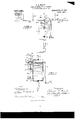
- the invention may be defined as consisting of the combinations of elements embodied in the claims hereto annexed and illustrated in one exempliication in the drawings forming part hereof, in which- Figure 1 represents a side elevation of a steam boiler furnace having my apparatus applied thereto; Fig. 2 represents a front elevation of the mechanism by which the furnace drafts are controlled; and Fig. 3 is a sectional detail of such mechanism.
- Describing the parts by reference characters 1 denotes a steam boiler furnace having a damper 2 through which air may be admitted to theV ash pit to promote combustion in the furnace proper.
- This damper is shown as a door which is pivoted to the front of the ash-pit.
- the pipe 9 denotes a pipe leading from the upper portion of the receptacle 6 to the lower portion of the boiler.
- the point at which pipe 9 communicates with the receptacle 6 will constitute an overflow for the liquid in the receptacle and Will serve, underv normal conditions, to maintain a level of liquid in said receptacle.
- the upper end of receptacle 6 is considerably above the water level in the boiler and the level of the liquid in the receptacle 6 is normally above the level of the liquid in the boiler.
- the pipe 9 is provided with a check valve 10, opening toward the boiler, whereby the flow of water from the boiler to the receptacle is prevented.
- a bracket 14 projects from the receptacle 6 and is preferably cast therewith.
- This bracket forms a support for the lower end of a rod 15 which carries at its upper end the yoke 16 having bearings 17 in the arms thereof.
- the bearings form a journal for a pipe section 18.
- This section carries a cross fitting 19 which is connected at one end with a pipe 20 extending to a receptacle 21.
- the other end of said tting is connected with a lever arm 22 having an adjustable weight 23 thereon.
- the pipe 20 and the arm 22 constitute opposite arms of a lever which is pivoted in the bearings 17.
- the yoke 16 is provided with extensions 24 arranged at right angles with respect to the yoke arms which have the bearings 17, and each extension 24 is provided with an adjustable stop 25, 25a, which are adapted to engage the opposite arms of the pivoted lever and limit the downward movements thereof.
- the lower end of the rod 15 is threaded and is provided with a pair of nuts 15a by means of which the yoke 16 may be vertically adjusted, thereby enabling the point of support of the lever to be varied with respect to the level of liquid in the tank 6.
- the receptacle 21 is provided with a vent opening 26 with a guide strap 27 extending across and above the same, said strap being provided with a perforation for a stem 28 having thereon a valve 29 adapted to close the orifice 26, said valve and stem being operated by means of a float 30 to which the stem is connected.
- a supply connection 31 having an elbow 32 provided with a valve, the stem of which is shown at 33.
- the arm 20 of the lever is connected with the damper 2 by means of a chain 35, while the opposite arm 22 is connected to the check draft damper l by means of a chain 36, the latter arm having a plurality of apertures 22a by means of which the point of connection of the chain 36 therewith may be varied.
- the operation will be as follows: lVhen the pressure within the boiler is at or below that which it is desired to maintain therein and in the syst-em connected therewith, the lever will be in the position shown in dotted lines in Fig. 1; that is to say, with the receptacle 21 elevated and the weighted arm of the lever depressed7 which will cause the air damper 2 to be opened and the check damper l to be closed.
- the pipe 11 slopes downwardly from the boiler toward the receptacle, thereby causing water of condensation to drain into said receptacle and maintain the maximum level therein. Any surplus water can run into the boiler through the pipe 9, its return into the receptacle 6 being prevented by means of the check valve 10.
- valve 37 in the pipe 11 which valve may be conveniently located near the bend, said valve being arranged to open at approximately and preferably slightly below atmospheric pressure, whereby it will be impossible for the water in the tank 6 to flow back into the boiler through pipe 11.
- a gage 38 carried by the receptacle 6 serves to indicate the level of the liquid therein and the pressure of the steam in the boiler.
- the intermediate receptacle-6 avoids the necessity for using water from the boiler to operate the receptacle 21.
Landscapes
- Engineering & Computer Science (AREA)
- Chemical & Material Sciences (AREA)
- Combustion & Propulsion (AREA)
- Mechanical Engineering (AREA)
- General Engineering & Computer Science (AREA)
- Control Of Steam Boilers And Waste-Gas Boilers (AREA)
Description
T. G. MOUAT.
PRESSURE REGULATING APPARATUS.
APPLICATION FILED APB.. 30, 1909. 937,686.` Patented Oct. 19, 1909. 2 SHEETS-SHEET l.
T. G. MOUAT. PRESSURE REGULATING APPARATUS.
APPLICATION FILED APB.. 30, 1909.
Patented 06f). 19, 1909.
2 SHEETS-SHEET z.
[mfr/fr mcniw. s. emma m. rammumomvnsns. msnmmo. u a
THOMAS G. MOUAT, OF B/BfTENAI-IL, VOHIO.
PRESSURE-REGULATING APTRATUS.
Application filed April 30, 1909.
Specification of Letters Patent.
Patented Oct. 19, 1909.
Serial No. 493,117.
To all 'whom tt may concern:
Be it known that I, THOMAS G. MoUAT, a citizen of the United States, residing at Bratenahl, in the county of Cuyahoga and State of Ohio, have invented a certain new and useful Improvement in Pressure-Regulating Apparatus, of which the following is a full, clear, and exact description, reference being had to the accompanying drawings.
This invention relates to apparatus for maintaining substantially constant the pressure and temperature of fluids, and is especially adapted for use in connection with low-pressure steam-heating systems.
It has for an object to provide an apparatus of this character which, while being extremely simple of construction, is eliicient and reliable in operation.
Generally speaking, the invention may be defined as consisting of the combinations of elements embodied in the claims hereto annexed and illustrated in one exempliication in the drawings forming part hereof, in which- Figure 1 represents a side elevation of a steam boiler furnace having my apparatus applied thereto; Fig. 2 represents a front elevation of the mechanism by which the furnace drafts are controlled; and Fig. 3 is a sectional detail of such mechanism.
In carrying out my invention, I make use of the variations in pressure of the steam in the boiler to displace a liquid from a receptacle, the liquid serving to operate suitable dampers to check the furnace drafts, and a counterpoise serving to operate the furnace drafts 1n the reverse direction when the pressure falls.
Describing the parts by reference characters 1 denotes a steam boiler furnace having a damper 2 through which air may be admitted to theV ash pit to promote combustion in the furnace proper. This damper is shown as a door which is pivoted to the front of the ash-pit.
3 denotes the iiue leading from the combustion chamber and provided with a checkdraft damper 4. Above and surrounding the combustion chamber is located the boiler proper, said boiler having therein a maintained water level, denoted by the broken line 5 5. At a suitable distance from the boiler there is provided a receptacle 6 supported on a suitable standard 7. This receptacle is provided with a filling opening having a closure 8.
9 denotes a pipe leading from the upper portion of the receptacle 6 to the lower portion of the boiler. The point at which pipe 9 communicates with the receptacle 6 will constitute an overflow for the liquid in the receptacle and Will serve, underv normal conditions, to maintain a level of liquid in said receptacle. As will appear by reference to Fig. 1, the upper end of receptacle 6 is considerably above the water level in the boiler and the level of the liquid in the receptacle 6 is normally above the level of the liquid in the boiler. The pipe 9 is provided with a check valve 10, opening toward the boiler, whereby the flow of water from the boiler to the receptacle is prevented.
11 denotes a pipe extending from the top of the receptacle 6 to the steam space of the boiler, being shown as connected to the dome 12. From this dome any suitable number of pipes 13 may extend to points of use as, for instance, to radiators for heating purposes.
A bracket 14 projects from the receptacle 6 and is preferably cast therewith. This bracket forms a support for the lower end of a rod 15 which carries at its upper end the yoke 16 having bearings 17 in the arms thereof. The bearings form a journal for a pipe section 18. This section carries a cross fitting 19 which is connected at one end with a pipe 20 extending to a receptacle 21. The other end of said tting is connected with a lever arm 22 having an adjustable weight 23 thereon. The pipe 20 and the arm 22 constitute opposite arms of a lever which is pivoted in the bearings 17. The yoke 16 is provided with extensions 24 arranged at right angles with respect to the yoke arms which have the bearings 17, and each extension 24 is provided with an adjustable stop 25, 25a, which are adapted to engage the opposite arms of the pivoted lever and limit the downward movements thereof. The lower end of the rod 15 is threaded and is provided with a pair of nuts 15a by means of which the yoke 16 may be vertically adjusted, thereby enabling the point of support of the lever to be varied with respect to the level of liquid in the tank 6. As the arm 2O and receptacle 21 are supplied from the receptacle 6 by the pressure of the steam in the boiler transmitted through pipe 11, it will be seen that this adjustment of the yoke affords a convenient means for varying the boiler pressure at which the dampers will be operated.
The receptacle 21 is provided with a vent opening 26 with a guide strap 27 extending across and above the same, said strap being provided with a perforation for a stem 28 having thereon a valve 29 adapted to close the orifice 26, said valve and stem being operated by means of a float 30 to which the stem is connected.
From the bottom of receptacle 6 there projects a supply connection 31 having an elbow 32 provided with a valve, the stem of which is shown at 33.
34 denotes a flexible pipe which connects the elbow 32 with the cross fitting 18.
The arm 20 of the lever is connected with the damper 2 by means of a chain 35, while the opposite arm 22 is connected to the check draft damper l by means of a chain 36, the latter arm having a plurality of apertures 22a by means of which the point of connection of the chain 36 therewith may be varied.
With the parts arranged as described, the operation will be as follows: lVhen the pressure within the boiler is at or below that which it is desired to maintain therein and in the syst-em connected therewith, the lever will be in the position shown in dotted lines in Fig. 1; that is to say, with the receptacle 21 elevated and the weighted arm of the lever depressed7 which will cause the air damper 2 to be opened and the check damper l to be closed. Should the pressure within the boiler exceed that which it is desired to maintain therein or in the system or apparatus connected therewith, this pressure actn ing through pipe 11 will force water from the receptacle 6 into the receptacle 21, causing said receptacle to fall to the position shown in full lines in Fig. 1; that is to say, until the pipe arm 20 engages the stop 25a. This stop will be so adjusted as to engage the arm 20 when the latter is approximately in a horizontal position. This movement of the lever will cause the check damper 4l to be opened and the air damper 2 to be closed. The provision of the flexible pipe 34; allows of the oscillation of the lever' comprising the arms 20 and 22 without affecting the connections therewith. When the pressure within the boiler falls below normal, water is drained completely from the receptacle 21, (the pivot for arm 2O being above the point of connection of pipe 9 with the receptacle 6) and a reverse operation of dampers 2 and 4: occurs.
It will be understood that, in first putting the apparatus into operation, it will be necessary to fill the receptacle 6 through the lling aperture. Should the pressure in the boiler increase, notwithstanding the operation of the dampers 2 and ,4, the float 30 and valve 29 will prevent the receptacle 21 from overflowing.
In order to prevent the vnecessity for relling the receptacle 6, the pipe 11 slopes downwardly from the boiler toward the receptacle, thereby causing water of condensation to drain into said receptacle and maintain the maximum level therein. Any surplus water can run into the boiler through the pipe 9, its return into the receptacle 6 being prevented by means of the check valve 10.
As the liquidA in the receptacle 6 is exposed to atmospheric pressure, through receptacle 21 and vent 26, it is necessary to provide against the emptying of said receptacle into the boiler in case the pressure in the boiler should fall below that of the atmosphere. I accordingly provide a valve 37 in the pipe 11, which valve may be conveniently located near the bend, said valve being arranged to open at approximately and preferably slightly below atmospheric pressure, whereby it will be impossible for the water in the tank 6 to flow back into the boiler through pipe 11. A gage 38 carried by the receptacle 6 serves to indicate the level of the liquid therein and the pressure of the steam in the boiler.
Among the advantages of the intermediate receptacle-6 is the fact that it avoids the necessity for using water from the boiler to operate the receptacle 21.
Having thus described my invention, what I claim is:
1. The combination, with a boiler and means for heating the same, of means for controlling said heating means,v the latter means comprising a receptacle, a connection between said receptacle and the water space of the boiler, a second connection between said receptacle and the steam space of the boiler, a lever pivoted intermediate of its ends and comprising a supply pipe, a receptacle supported by the lever and, communicating with the supply pipe, a flexible connection extending between said supply pipe and the first mentioned receptacle, means for limiting the movement of the supply pipe and receptacle, and connections operative by the movement of the latter receptacle for varying the pressure of the steam generated by the boiler.
2. The combination, with a boiler and means for heating the same, said means comprising an air damper and a check damper, of means for automatically operating said dampers in reverse directions, the latter means comprising a receptacle, a connection between said receptacle and the steam space in the boiler, a drain connection extending between said receptacle and the water space of the boiler and provided with a check valve adapted to open toward the boiler7 a lever pivoted intermediate of its ends and having one arm provided with a receptable,
connections .for supplying liquid from the former receptacle to the latter receptacle, and connections between the lever armsA and the said dampers for opening the latter by reverse movements of the second receptacle.
3. The combination, with a boiler and furnace, of means for maintaining-substantially constant pressure of the steam generated by said boiler, said means comprising a receptacle provided with a connection extending from between the top and bottom thereof to the water space in the boiler, a pipe connecting said receptacle with the steam space in the boiler, a lever pivoted intermediate of its ends at a point as high as the level of the liquid in said receptacle, said lever having a hollow arm extending from the pivotal portion thereof, a receptacle on said arm and communicating therewith, a flexible connection extending between the iirst mentioned receptacle and the pivotal point of the lever, stops for limiting the movements of said lever, and connections extending from the opposite arms of said lever and arranged to control the combustion in the furnace.
4. The combination, with a boiler and furnace, of means for maintaining substantially constant the pressure of steam generated by said boiler, said means comprising a receptacle arranged externally of said boiler and extending above the level of water therein, a pipe connecting said receptacle with the water space of the boiler and arranged to maintain a maximum level in said receptacle, a second pipe connecting said receptacle with the steam space in the boiler, a bracket carried by said receptacle and having a pivot support and adjustable stops arranged on opposite sides of said support, a lever, a pipe section supporting said lever and supported by said pivot support, a flexible connection between said section and said receptacle, one of the arms of said lever being hollow and communicating with said pipe section, a receptacle carried by said hollow arm, and connections extending from the opposite arms of the lever and adapted to control the heating effect of the furnace upon the boiler.
5. The combination, with a boiler, of means for maintaining substantially constant the pressure of steam generated by said boiler, said means comprising a receptacle having its upper end above the level of liquid in the boiler, a pipe connecting said receptacle with the water space in the boiler and having a check valve therein, said pipe being arranged to maintain a maximum level of liquid in said receptacle, a pipe connecting the upper portion of said receptacle with the steam space of the boiler, a second receptacle, connections between said receptacles, and means operated by the movement of the latter receptacle for controlling the heat imparted to the boiler to generate steam therein.
6. The combination, with a boiler and means for heating the same, of means for maintaining substantially constant the pressure of steam generated thereby, said means comprising a receptacle, a pipe connecting said receptacle with the water space in the boiler and extending above the bottom of said receptacle, a pipe connecting the upper portion of said receptacle with the steam space of the boiler and arranged to drain toward said receptacle, a movably supported receptacle communicating with the former receptacle and having a vent opening, a valve in the last mentioned pipe arranged to admit air thereto on the fall of pressure in said pipe, and connections between the latter receptacle and the means for heating said boiler.
7. The combination, with a boiler and means for heating the same, of means for maintaining substantially constant the pressure of steam generated thereby, said means comprising a receptacle, a pipe connecting said receptacle with the water space in the boiler and extending above the bottom of said receptacle, a pipe connecting the upper portion of said receptacle with the steam space of the boiler and arranged to drain toward said receptacle, a movably supported receptacle communicating with the former receptacle, and connections between said receptacle and the means for heating said boiler.
8. The combination, with a boiler and means for heating the same, of means for controlling said heating means, the latter means comprising a receptacle, a bracket, bearings carried by said bracket and receptacle, a pair of adjustable stops located on opposite sides of said bearings, a lever pivoted intermediate of its ends in said bearings, one arm of said lever comprising a pipe, a supply pipe arm communicating with said receptacle and said pipe, a second receptacle carried by said pivoted pipe, means dependent upon the pressure of steam in the boiler for supplying liquid from the rst receptacle through the flexible pipe, and connections between the second receptacle and the heatingmeans.
9. The combination, with a boiler and means for heating the same, of means for controlling said heating means, the latter means comprising a receptacle, a pipe connecting said receptacle with the water space of said boiler and adapted to convey liquid from said receptacle to said boiler, a second pipe communicating with the steam space of the boiler and with said receptacle, a bracket projecting from said receptacle, a yoke supported by said bracket and vertically adjustable with respect thereto, a lever pivoted to said yoke, a receptacle carried by said lever, a connection between said receptacles, and a connection between the second receptacle and the boiler heating means.
10. The combination, with a boiler and means for heating the same, of means for maintaining substantially constant the pressure of steam generated by said boiler, said means comprising a receptacle extending above the water line of the boiler, a pipe connecting said receptacle with the boiler and extending above the bottom of said receptacle, a pipe connecting said receptacle with the steam space of the boiler and arranged to drain toward said receptacle, a movably supported receptacle communicating with the former receptacle and arranged to drain into the former receptacle, and connections between the latter receptacle and the means for heating the boiler.
ll. The combination, with a boiler and furnace, of means for maintaining substantially constant the pressure of the steam generated by said boiler, said means comprising a receptacle extending above the level of water in the boiler and provided with a connection extending from between the top and bottom thereof and the water space in the boiler, a pipe connecting said receptacle with the steam space in the boiler, a lever pivoted intermediate of its ends at a point as high as the level of the liquid in said receptacle, said lever having a hollow arm extending from the pivotal portion thereof, a receptacle on said arm and communicating therewith, means connecting the first mentioned receptacle and the pivotal portion of the lever, a stop for limiting the downward movement of the lever arm which carries the second receptacle, and connections extending from the opposite arms of said lever and arranged to control the combustion in the furnace.
In testimony whereof, I hereunto affix my signature in the presence of two witnesses.
THOMAS Gr. MOUAT.
l/Vitnesses:
J. B. HULL, BRENNAN B. WEST.
Priority Applications (1)
| Application Number | Priority Date | Filing Date | Title |
|---|---|---|---|
| US49311709A US937686A (en) | 1909-04-30 | 1909-04-30 | Pressure-regulating apparatus. |
Applications Claiming Priority (1)
| Application Number | Priority Date | Filing Date | Title |
|---|---|---|---|
| US49311709A US937686A (en) | 1909-04-30 | 1909-04-30 | Pressure-regulating apparatus. |
Publications (1)
| Publication Number | Publication Date |
|---|---|
| US937686A true US937686A (en) | 1909-10-19 |
Family
ID=3006107
Family Applications (1)
| Application Number | Title | Priority Date | Filing Date |
|---|---|---|---|
| US49311709A Expired - Lifetime US937686A (en) | 1909-04-30 | 1909-04-30 | Pressure-regulating apparatus. |
Country Status (1)
| Country | Link |
|---|---|
| US (1) | US937686A (en) |
-
1909
- 1909-04-30 US US49311709A patent/US937686A/en not_active Expired - Lifetime
Similar Documents
| Publication | Publication Date | Title |
|---|---|---|
| US1979299A (en) | Feed water regulator | |
| US1041272A (en) | Valve-regulating mechanism. | |
| US1635274A (en) | Pressure regulator | |
| US402076A (en) | Automatic heat-regulator for hot-water heating apparatus | |
| US462005A (en) | Island | |
| US954643A (en) | Damper and air-regulator. | |
| US1199726A (en) | Boiler-pressure regulator. | |
| USRE14093E (en) | Steam-eurltace-regtrlatingr system | |
| US1588049A (en) | Feed-water regulator | |
| US1491533A (en) | Valve mechanism for steam radiators | |
| US864807A (en) | Boiler-feeder. | |
| US1447858A (en) | Vapor-contbolling system | |
| US2387576A (en) | Heating system | |
| US1304106A (en) | Method oe steam-heating | |
| US413789A (en) | Automatic draft regulator | |
| US1797096A (en) | Heating plant | |
| US439749A (en) | Boiler feeder and regulator | |
| US52115A (en) | Improvement in automatic steam-generators | |
| US1005156A (en) | Boiler feed-water regulator. | |
| US1284748A (en) | Pressure-regulating apparatus. | |
| US509152A (en) | Heat-regulating device for stoves or other heaters | |
| US1562498A (en) | Flasher steam heating apparatus | |
| US1194785A (en) | Wateb-heateb | |
| US1318514A (en) | Island | |
| US1094382A (en) | Regulator for hot-water heating systems. |