US937472A - Door-knob. - Google Patents
Door-knob. Download PDFInfo
- Publication number
- US937472A US937472A US1904197696A US937472A US 937472 A US937472 A US 937472A US 1904197696 A US1904197696 A US 1904197696A US 937472 A US937472 A US 937472A
- Authority
- US
- United States
- Prior art keywords
- knob
- door
- spindle
- clutch
- plates
- Prior art date
- Legal status (The legal status is an assumption and is not a legal conclusion. Google has not performed a legal analysis and makes no representation as to the accuracy of the status listed.)
- Expired - Lifetime
Links
- 241000220317 Rosa Species 0.000 description 1
- 230000001788 irregular Effects 0.000 description 1
Images
Classifications
-
- E—FIXED CONSTRUCTIONS
- E05—LOCKS; KEYS; WINDOW OR DOOR FITTINGS; SAFES
- E05B—LOCKS; ACCESSORIES THEREFOR; HANDCUFFS
- E05B3/00—Fastening knobs or handles to lock or latch parts
- E05B3/003—Fastening knobs or handles to hollow cylindrical spindles, e.g. of tubular locks
-
- Y—GENERAL TAGGING OF NEW TECHNOLOGICAL DEVELOPMENTS; GENERAL TAGGING OF CROSS-SECTIONAL TECHNOLOGIES SPANNING OVER SEVERAL SECTIONS OF THE IPC; TECHNICAL SUBJECTS COVERED BY FORMER USPC CROSS-REFERENCE ART COLLECTIONS [XRACs] AND DIGESTS
- Y10—TECHNICAL SUBJECTS COVERED BY FORMER USPC
- Y10T—TECHNICAL SUBJECTS COVERED BY FORMER US CLASSIFICATION
- Y10T292/00—Closure fasteners
- Y10T292/85—Knob-attaching devices
- Y10T292/865—Sliding
Definitions
- This invention relates to door knobs, and has for its object the provision in a door knob of a divided interlocking supporting plate or plates for securing in place a clutch which locks the knob fromunscrewing on the spindle.
- the invention consists of the production of a novel and eflcient door knob, having the above referred to features and the several improvements and combinations of parts set forth and claimed hereinafter.
- the parts designated by the letter A represent a door and, B the knob, with its shank or neck C.
- the clutch E is a clutch consisting, as shown, of a substantially flat circular body, having a square axial perforation e, and lateral anges or lugs F, to take into corresponding grooves or depressions N in the end of the shank C of the knob B.
- the clutch E is adapted to slide upon the spindle D, but as it is incapable of rotation thereon, when it is engaged with the knob shank, it also prevents the knob and shank from rotation independently of the spindle.
- G designates two supporting plates having substantially semi-circular collars or flanges H, adapted to it about the spindle D between t-he door A and clutch E, and when in that position prevent the movement of the clutch E longitudinally on the spindle out of engagement with the knob shank.
- Each of these clutch supporting plates G has portions I, projecting on two sides beyond the center of the circle of which the flange H forms an arc, so that pressure on these ends will not tend to tilt or dislocate the clutch.
- Both supporting plates have recesses P which are adapted when the two plates are in position to receive the projecting portions of the other plates, so that the two plates interlock to form a continuous base or support by means of the Hanges H (which thus together extend around the spindle) against the clutch, as shown more particularly in Fig. 7.
- the supporting plates G may be provided with elongations K which prolong the plates to a length greater than one-half the transverse axis of the escutcheon, so that when an elongated or oblong escutcheon or rose is used, as shown at M in the drawings, the escutcheon M may be turned horizontally, as suggested in the lighterdotted lines (Fig. 4) in which position the elongated ends K of the supporting plates will project beyond the sides of the escutcheon and the plates may be secured by screws or other means, in the perforations L, to the door. When the escutcheon M is turned back to its normal vertical position, as shown in heavier dotted lines in Fig. 4, it will cover the supporting plates thus secured in place.
- each of the flanges H of the supporting plates are beveled, so that they may be used as a wedge to force the clutch E home into engagement with the door shank, when the supporting plate is slid into position.
- a knob attachment the combination with a screw threaded spindle; of a knob adapted to be screwed thereon; a clutch slidable on said spindle and rotatable therewith adapted to engage said knob; a continuous support around said spindle between the 15 In witness whereof I have hereunto set my 20 hand on the 19th day of February, 1904.
Landscapes
- Engineering & Computer Science (AREA)
- Mechanical Engineering (AREA)
- Mechanical Operated Clutches (AREA)
Description
J. H. SHAW.
DOOR KNOB. PPLIUATIoN FILED MAR. 11'. 1904.
' W/ TNESSES:
.inw
J. H. SHAW.
DOOR KNOB. PPLIoA'rIoN FILED 11.13.11. 1904.
93.7",1-1'72,` Patented Oct. 19, 1909,
2 SHEETS-SHEET 2.
Wl TN E SSE S lNVENTO UNITED STATES PATENT FFIC.
JOI-IN H. SHAW, OF NEW HAVEN, CONNECTICUT, ASSIGNOR TO SARGENT & COMPANY,
0F NEW HAVEN, CONNECTICUT, A CORPORATION OF CONNECTICUT.
DOOR-KNOB.
specification of Letters raient.
Patented Oct. 19, 1909.
Application led March 11, 1904. Serial No. 197,696.
To all whom it may concern:
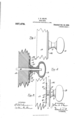
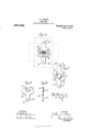
Be it known that I, JOHN H. SHAW, of the city and county of New Haven, in the State of Connecticut, have invented new and useful Improvements in Door-Knobs, of which the following is a full, clear, and exact description, when t-aken in connection with the accompanying drawings, which form a part thereof, and in which- Figure l represents a side elevation of a knob attachment embodying my invention, Fig. 2, a similar view with the escutcheon plate moved away from the door, Fig. 3, a vertical central section through the same in the positions shown in Fig. l, Fig. 4, a transverse vertical section on line H of Fig. 2, Figs. 5 and 6, front and side elevations, respectively of one of the supporting plates, in detail, Fig. 7, a detail front View of the supporting plates shown interlocked, and Fig. 8, a detail front view of the clutch.
In all figures, similar letters of reference represent like parts.
This invention relates to door knobs, and has for its object the provision in a door knob of a divided interlocking supporting plate or plates for securing in place a clutch which locks the knob fromunscrewing on the spindle.
The invention consists of the production of a novel and eflcient door knob, having the above referred to features and the several improvements and combinations of parts set forth and claimed hereinafter.
Referring to the drawings for a more particular description, the parts designated by the letter A represent a door and, B the knob, with its shank or neck C.
D is the spindle, square in cross section, with its corners threaded in well known manner (Fig. 4). The interior of the shank C is internally threaded to engage with the threading on the spindle (Fig. 3).
E is a clutch consisting, as shown, of a substantially flat circular body, having a square axial perforation e, and lateral anges or lugs F, to take into corresponding grooves or depressions N in the end of the shank C of the knob B. The clutch E is adapted to slide upon the spindle D, but as it is incapable of rotation thereon, when it is engaged with the knob shank, it also prevents the knob and shank from rotation independently of the spindle.
G designates two supporting plates having substantially semi-circular collars or flanges H, adapted to it about the spindle D between t-he door A and clutch E, and when in that position prevent the movement of the clutch E longitudinally on the spindle out of engagement with the knob shank. Each of these clutch supporting plates G has portions I, projecting on two sides beyond the center of the circle of which the flange H forms an arc, so that pressure on these ends will not tend to tilt or dislocate the clutch. Both supporting plates have recesses P which are adapted when the two plates are in position to receive the projecting portions of the other plates, so that the two plates interlock to form a continuous base or support by means of the Hanges H (which thus together extend around the spindle) against the clutch, as shown more particularly in Fig. 7.
The supporting plates G may be provided with elongations K which prolong the plates to a length greater than one-half the transverse axis of the escutcheon, so that when an elongated or oblong escutcheon or rose is used, as shown at M in the drawings, the escutcheon M may be turned horizontally, as suggested in the lighterdotted lines (Fig. 4) in which position the elongated ends K of the supporting plates will project beyond the sides of the escutcheon and the plates may be secured by screws or other means, in the perforations L, to the door. When the escutcheon M is turned back to its normal vertical position, as shown in heavier dotted lines in Fig. 4, it will cover the supporting plates thus secured in place.
As shown more particularly in Figs. 2, 5 and G, the ends of each of the flanges H of the supporting plates are beveled, so that they may be used as a wedge to force the clutch E home into engagement with the door shank, when the supporting plate is slid into position.
Having now described my invention, (which may vary in its details without departing from the spirit thereof) what I claim and desire to secure by Letters Patent is l. In a knob attachment, the combination with a screw threaded spindle; of a knob adapted to be screwed thereon a clutch capable of longitudinal movement on said spindle and only rotatable therewith adapted to engage said knob; and a support around said spindle for said clutch to hold it in engagement with said knob, said support consisting of two or more plates adapted to be assembled by movement toward each other edgewise, the plates when assembled forming together a support of the thickness of each plate, and the line of division between said plates being` irregular with lateral recesses in one plate and corresponding projections in the other, substantially as described.
2. In a knob attachment, the combination with a screw threaded spindle; of a knob adapted to be screwed thereon; a clutch slidable on said spindle and rotatable therewith adapted to engage said knob; a continuous support around said spindle between the 15 In witness whereof I have hereunto set my 20 hand on the 19th day of February, 1904.
JOHN I-I. SHAW.
Vitnesses:
M. O. WILLIAMS, SAMUEL H. FISHER.
Priority Applications (1)
| Application Number | Priority Date | Filing Date | Title |
|---|---|---|---|
| US1904197696 US937472A (en) | 1904-03-11 | 1904-03-11 | Door-knob. |
Applications Claiming Priority (1)
| Application Number | Priority Date | Filing Date | Title |
|---|---|---|---|
| US1904197696 US937472A (en) | 1904-03-11 | 1904-03-11 | Door-knob. |
Publications (1)
| Publication Number | Publication Date |
|---|---|
| US937472A true US937472A (en) | 1909-10-19 |
Family
ID=3005893
Family Applications (1)
| Application Number | Title | Priority Date | Filing Date |
|---|---|---|---|
| US1904197696 Expired - Lifetime US937472A (en) | 1904-03-11 | 1904-03-11 | Door-knob. |
Country Status (1)
| Country | Link |
|---|---|
| US (1) | US937472A (en) |
-
1904
- 1904-03-11 US US1904197696 patent/US937472A/en not_active Expired - Lifetime
Similar Documents
| Publication | Publication Date | Title |
|---|---|---|
| US55115A (en) | Thomas kennedy | |
| US1111425A (en) | Adjustable strike-plate. | |
| US1201003A (en) | Switch or terminal box. | |
| US1083529A (en) | Reversible box-strike for locks. | |
| US743475A (en) | Lock. | |
| US824330A (en) | Device for fastening cabinet-hardware. | |
| US382086A (en) | Door-button | |
| US708336A (en) | Door-knob. | |
| US1031287A (en) | Sash-center. | |
| US692265A (en) | Knob attachment. | |
| US1173007A (en) | Lock. | |
| US997074A (en) | Lock. | |
| US368640A (en) | Combination-lock | |
| US1066131A (en) | Turn-knob plate. | |
| USD23731S (en) | Design for a shelf-bracket | |
| US780951A (en) | Sash-lock. | |
| US769146A (en) | Combination-lock. | |
| US923755A (en) | Roll-back hub for locks. | |
| US180239A (en) | Improvement in knob-latches | |
| US857031A (en) | Center for locks. | |
| US326920A (en) | Henry e | |
| US1150450A (en) | Door-bolt. | |
| US487969A (en) | Russell sargent | |
| US764014A (en) | Lock. | |
| US942274A (en) | Snatch-block. |