US937394A - High-speed reducing-valve for air-brakes. - Google Patents
High-speed reducing-valve for air-brakes. Download PDFInfo
- Publication number
- US937394A US937394A US48848609A US1909488486A US937394A US 937394 A US937394 A US 937394A US 48848609 A US48848609 A US 48848609A US 1909488486 A US1909488486 A US 1909488486A US 937394 A US937394 A US 937394A
- Authority
- US
- United States
- Prior art keywords
- valve
- pressure
- brake cylinder
- piston
- port
- Prior art date
- Legal status (The legal status is an assumption and is not a legal conclusion. Google has not performed a legal analysis and makes no representation as to the accuracy of the status listed.)
- Expired - Lifetime
Links
- 230000000717 retained effect Effects 0.000 description 5
- 238000010276 construction Methods 0.000 description 4
- 230000006872 improvement Effects 0.000 description 3
- 230000009467 reduction Effects 0.000 description 3
- 238000009825 accumulation Methods 0.000 description 2
- 230000007246 mechanism Effects 0.000 description 2
- 241001052209 Cylinder Species 0.000 description 1
- 230000009471 action Effects 0.000 description 1
- 230000000694 effects Effects 0.000 description 1
- 239000012530 fluid Substances 0.000 description 1
- 150000002500 ions Chemical class 0.000 description 1
- 230000004048 modification Effects 0.000 description 1
- 238000012986 modification Methods 0.000 description 1
Images

Classifications
-
- B—PERFORMING OPERATIONS; TRANSPORTING
- B60—VEHICLES IN GENERAL
- B60T—VEHICLE BRAKE CONTROL SYSTEMS OR PARTS THEREOF; BRAKE CONTROL SYSTEMS OR PARTS THEREOF, IN GENERAL; ARRANGEMENT OF BRAKING ELEMENTS ON VEHICLES IN GENERAL; PORTABLE DEVICES FOR PREVENTING UNWANTED MOVEMENT OF VEHICLES; VEHICLE MODIFICATIONS TO FACILITATE COOLING OF BRAKES
- B60T11/00—Transmitting braking action from initiating means to ultimate brake actuator without power assistance or drive or where such assistance or drive is irrelevant
- B60T11/10—Transmitting braking action from initiating means to ultimate brake actuator without power assistance or drive or where such assistance or drive is irrelevant transmitting by fluid means, e.g. hydraulic
- B60T11/16—Master control, e.g. master cylinders
- B60T11/228—Pressure-maintaining arrangements, e.g. for replenishing the master cylinder chamber with fluid from a reservoir
Definitions
- This invention relates to fluid pressure- 1 sting in emergency applications to permit the accumulation of e higher degree of pressure in the brake cylinder, such as set forth in my prior pending applications, Ser. No. 191129, filed Jun. 29, 1904;, and See. No. 223823 filed Sept. 9, 190%.
- the brake cylinder pressure in service applications is limited to a predetermined safe degree which will not ordinarily produce sliding oi the car wheels even at very slow speed, while in eu'icrgency applications the full initial pressure that may be admitted to the brake cylinder-is retained lherein for a limited period of time and then blown down to the same predetermined degree which is maximum for service e 'u'alications, the object being to hold the full initial brake cylinder pressusc in emergency applications a suilicient period of time to effect a. retardation or reduction in speed to such a rate that wheel sliding might be imminent and to then reduce the excessive brake cylinder pressure tothe safe limit for ordinary low speeds.
- Another ohjeet is so gavovide on improved velvc device which may be readily adjusted to give any result desired, such as to hold the full brake cylinder pressure continuously in emergency applications, or to hold the full initial brake cylinder pressure a prcdetermined time and then to blow down to at certain degree which shall hehornter to any desired extent. than the predetermined maximum to which'the brake cylinder pressure is limited in service applications.
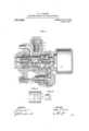
- Figure l is a vertical section illustrating one form of valve device embodying my improvements
- Fig. 2 a plan view of the slide valve seat:
- Fig. 3 a face view of the slide valve;
- Fig. i a vertical section showing a modified form of valve device;
- Fig. 5 s vertical sectional view showing still another mdiiica-' tion.
- valve device coinprises e casing having an inlet 1 communicating with the brake cylinder, 21, valve chamber 2, piston chambers and l, conaining pistons 6 and 7 on stem for operating the slide valve 8.
- a normally open port leads from the valve seat to diaphragm.
- chamber 15 having din hragm 16 with adjustable spring 26 and stem 30 for opersting the vent valve 17 which controls the flow of air from the chamber 3 through passage l9 and port 20 to the. atmosphere.
- Chamber communicates with chamber 4: heel: of piston 7 in order to furnish the desired volume, and a normally open by-pass port 22 establishes communication. around 'the piston, out is adapted to be closed by the movement of the device in emergency applications when the piston 7 seats against its gasket 21.
- a restricted port 23 is provided for gradually equalizing the brake cylinder pressure into chamber 25.
- Air from the brake cylinder is adapted to leak armind the loosclyfitting piston 6, or a very small port 24 may be made through the piston for this purpose.
- the outlet port 9 is controlled by slide valve 8, having a port 31 adapted to register with the outlet port in a certain positions of the valve, and an additional port;
- valve 27 governing an outlet port 29 28 the .valve 27 maybe sired degree of pressure in the brake cyl1nprovement is as follows:
- this portion of the valve device might be'said to comprise a safety valve of the slide valve type for limiting the brake cylinder pressure to a predetermined a mount.
- a cavity 32 inay be provided in the face of the valve 8 for-connecting the port 10 with the outlet port 9 and the atmosphere in this position of the valve for the purpose of preventing the accumulation of pressure in the diaphragm chamberloqdue to accidental leakage or other cause.
- the pressure equalizes'upon the piston 7, the spring 14, which was compressed by the first movement of said piston now expands and moves the pistons and slide valve back to normal position, but as this operates to open port 10 and admit the excessively high brake cyl inder pressure into diaphragm chamber 15, the diaphragm 16 instantly .com resses spring 26 and opens wide the vent va ve 17.
- the port 31 may be so .located or, what amounts tothe same thin greater or less higher degree in a the length of stem 12 may be so ad usted as to permit the port 9 to be slightly open in this extreme position of the valve, thus allowing the brake cylinder pressure to gradually reduce to that for which the spring 26 is set, whereupon the valve 8 returns to its normal position and closes the outlet port 9,' as before-described.
- the port 33 and spring seated valve 27' may be provided for this purpose,'the port 38 being so located as to be opened by the slide valve in emergency applications.
- season spring 28 maybe adjusted to hold any do sired degree, say 75- peu'nds or square inch,
- the device as shown in Fig. l operates substantially as before described, but the restricted port 23 is omitted from piston 7 in ordcnto prevent any escape of air through this piston when the same is seated against the gasket in emergency applicat'ions.
- the diaphra in with its adjustable spring and vent. va ve, pistonfi and slide valve 8 comprise the safety valve or blow all part or the device for limiting the brake cylinder pressure to a predeterir'iincd degree in service applications, while the piston 7 with the slide valve 8 comprise the emergency feature of the device for cutting out of action the low pressure blow ofi' device in emergency applications, the slide valve 8 being conveniently arranged to ser'veas a part of both of these features. It will'also be evident that these features may be separatelyarrangcd, and that any desirable or common form of low pressure blow ed valve may be used in lieu of the slide valve type. Such an arrangement is shown in Fig. 5 n which an ordinary blow of?
- valve 8 havmg an &Cl]llSlC able spring Q6 is connected by port 10 to the valve chamber 2, and the emergency piston 7 with its valve 8 is adapted to cut oil com- 'munication from the brake cylinder and chamber 2 to the port 10 and the low pressure blow ofi valve 8 in emergency applications.
- the port 33 leading to the high pressure blow 0d valve 27 is constantly open and in communication with the brake cylinder, but will perform no function in service applications since the valve 8' discharges the excess of air pressure and does not permit the same to rise sufiiciently high to open the valve 27.
- the pressure readily equalizes from the valve chamber 2 through ports 10 and 10 to cham-.
- hers 25 and 4 on the opposite side of piston 7 in service applications the spring 11 holds the piston and slide valve in the normal position with port 10 open so that the brake cylinder pressure is limited to the degree for which-the spring 26 of the low pressure blow ofi device is adjusted.
- a pplicetions the rapid rise in brake cylinder pressure seats the piston 'l'lagainst its gasket and moves valve 8 to cut out the low pressure de- ,vice and open-communication from the space 4 on the outer side of piston? to the atmosphere through ports l0, 10, 32 and 9.
- the brake cylinder pressure is then governed by the high pressure blow oil valve 27 and may be blown down more or less slowly, as desired, by adjusting the size of the ports, as will be readily understood.
- the brake cylinder pressure may be limited to a predetermined amount in service applications. while in emergencyv applications the full maximum pressure may be'retained throughout the entire period of the stop, or'mav be retained for a predetermined interval and then gradually reduced either to the maximum degree allowed in service applications or to a degree more or less greater than this. or may be gradually reduced to said higher degree of resultant pressure without a predetermined time interval of full maximum pressure.
- a high speed valve device for air brakes comprieinga blow oil mechanism for limiting the brake cylinder pressure to a predetermined degree in service applications, and means operating in emergency applications for retaining a higher ultimate degree f brake cylinder pressure.
- a high speed valve device for air brakes comprising a blow oil mechanism for limiting the brake cylinder pressure to a pre- I
Landscapes
- Engineering & Computer Science (AREA)
- Transportation (AREA)
- Mechanical Engineering (AREA)
- Valves And Accessory Devices For Braking Systems (AREA)
Description
W. V. TURNERP HIGH mm) nnnucme VALVE FOR AIR BRAKES.
APPLICATION FILED MAY 26, 1905. RENEWED APR. 7, 1909. 5,394 Patented Oct, 19, 1909.
2 SHEETS-SHEET 1.
"M58858 INVENTOR W. VPTURNER.
HIGH SPEED REDUCING VALVE FOR AIR BRAKES.
APPLICATION FILED MAY 26, 1905. nnnnwsn APR. 7, 1909.
937,394., 7 Patented 0ct.19,1909.
2 SHEETS-SHEET 2.
WITNESSES INVENTOR @MMAWMZA. 7 {m enliven sunr ses Funnier oiusicn- "WALTER V. TURNER, OI" WILE'ZINSBU'EG, PENN SYLVANIA, ASSIGNOFJ TO THE WESTING- HOUSE AIR BRAKE COM'EJl'Y, OF PYE'IJSBUli-Ki, PENNSYLVANIA, A GOBPGRATION OF PENNSYLVANIA.
Specification of Leisure Patent.
Patented 9st. 1%, @309.
/ duplication filed may 26, 1805, serial Ho. 282 1141. Renewed. April 7, 1909. serial No. 4288.486.
To all whom it may concern:
Be it known that I, WALTER V. Tonnes, a citizen of the United States, residing in Wilhinsburg, in the county of Allegheny and State of Pennsylvania, have invented a certein new and useful Improvement in High- Speed Reducing-Valves for Air-Brakes, of which the following is a specification.
This invention relates to fluid pressure- 1 sting in emergency applications to permit the accumulation of e higher degree of pressure in the brake cylinder, such as set forth in my prior pending applications, Ser. No. 191129, filed Jun. 29, 1904;, and See. No. 223823 filed Sept. 9, 190%.
According to these prior devices, the brake cylinder pressure in service applications is limited to a predetermined safe degree which will not ordinarily produce sliding oi the car wheels even at very slow speed, while in eu'icrgency applications the full initial pressure that may be admitted to the brake cylinder-is retained lherein for a limited period of time and then blown down to the same predetermined degree which is maximum for service e 'u'alications, the object being to hold the full initial brake cylinder pressusc in emergency applications a suilicient period of time to effect a. retardation or reduction in speed to such a rate that wheel sliding might be imminent and to then reduce the excessive brake cylinder pressure tothe safe limit for ordinary low speeds. It hes been found .in practice, however, that when a train is running cl: e high rate oi speed and the brakes are supplied in emergency application, a much higher broke cylinder pressure may he maintained and for a, longer period of time then it was at first supnosed without. danger of causing a sliding of'the wheels, and. one of the objects of mypresent invention is to mvide on improved valve device which wil npemme to hold a higher resultent hrnhc cylinder pressure in. emergency appliceitions their in service applications.
Another ohjeet is so gavovide on improved velvc device which may be readily adjusted to give any result desired, such as to hold the full brake cylinder pressure continuously in emergency applications, or to hold the full initial brake cylinder pressure a prcdetermined time and then to blow down to at certain degree which shall he greuter to any desired extent. than the predetermined maximum to which'the brake cylinder pressure is limited in service applications.
In the accompanying drawings, Figure l is a vertical section illustrating one form of valve device embodying my improvements; Fig. 2 a. plan view of the slide valve seat: Fig. 3 a face view of the slide valve; Fig. i a vertical section showing a modified form of valve device; and Fig. 5 s vertical sectional view showing still another mdiiica-' tion.
According to the preferred construction, as shown in Fig. 1, the valve device coinprises e casing having an inlet 1 communicating with the brake cylinder, 21, valve chamber 2, piston chambers and l, conaining pistons 6 and 7 on stem for operating the slide valve 8. Springs 1.1 and 14,
with stems 12 and 13 operate to norrmllly' hold the pistons and valve in the central position, as shown. A normally open port leads from the valve seat to diaphragm. chamber 15 having din hragm 16 with adjustable spring 26 and stem 30 for opersting the vent valve 17 which controls the flow of air from the chamber 3 through passage l9 and port 20 to the. atmosphere. Chamber communicates with chamber 4: heel: of piston 7 in order to furnish the desired volume, and a normally open by-pass port 22 establishes communication. around 'the piston, out is adapted to be closed by the movement of the device in emergency applications when the piston 7 seats against its gasket 21. A restricted port 23 is provided for gradually equalizing the brake cylinder pressure into chamber 25. Air from the brake cylinder is adapted to leak armind the loosclyfitting piston 6, or a very small port 24 may be made through the piston for this purpose. The outlet port 9 is controlled by slide valve 8, having a port 31 adapted to register with the outlet port in a certain positions of the valve, and an additional port;
33 may be provided leading to a spring seated. valve 27 governing an outlet port 29 28 the .valve 27 maybe sired degree of pressure in the brake cyl1nprovement is as follows:
2 g g n 937,394
to the atmosphere. By adjusting the spring pressure in service applicationslslimited by thecapacityof the service port. ofthe triple valve and the capacity of the by-pass ports 22 and 23 is sufiicient to permit the pressure to equalize into the chambers 4t and 25 without moving the piston 7 The pressure also equalizes around the piston 6 and throughport 24 into chamber 3, so that the pressure rises in all'parts of the valve device at substantially the same rate as that of the'brake cylinder and no movement of the valve occurs in service applications until the pressure acting through passage 10 a'ndin diaphragm chamber increases'to the point for which the spring 26 is adjusted. If a higher pressure than this be admitted to the brake cylinder the diaphragm 16 will be forced outward, compressing spring 26. and moving the stem and vent valve 17 to open the port 20, thereby producing a reduction in pressure in the chamber 3 and causing the movement of the piston 6 and slide valve 8- to bring port 31 in register with outlet port plied to the 9. This port remains open as long as air pressure in excess of that for which the; spring 26 .is adjusted continues to be sup brake cylinder, and thereby limits the brake clinder pressure in service applications to this predetermined degree. When the triple valve' cuts oil the s lDply to the brake cylinder and the pressure there- 1n diminishes slightly the spring 26' moves the stennBO away from the 'valve17 and permits the spring 18 to close the same, whereupon the pressure instantly equalizing upon opposite sides of the piston 6, the spring 1] expands and moves the piston and slide valve back to normal position, thereby close ing the outlet port 9. To the extent just described this portion of the valve device might be'said to comprise a safety valve of the slide valve type for limiting the brake cylinder pressure to a predetermined a mount.
since the cmergenc piston 7 remains inert" and performs no function in service applica trons. In emergency applications the pressure as admitted to the brake cylinder increases much more rapidly than in service and much faster than it can equalize around the piston 7 through ports 22 and :23, consequently as the piston 7 is of larger diameter than pistoil it is instantly carried over to its seat against gasket 21, thereby moving the valve 8 to close ports-10 and 29 and hold outlet set to hold any deport 9 also closed. In this position air under pressure from the rake cylinder feeds slowly through the res icted port 23 into the chamber 25 until he pressure therein substantially equalizos, nd this requires a predetermined period. of time during which the high pressure is held in the brake cylinder- A cavity 32 inay be provided in the face of the valve 8 for-connecting the port 10 with the outlet port 9 and the atmosphere in this position of the valve for the purpose of preventing the accumulation of pressure in the diaphragm chamberloqdue to accidental leakage or other cause. \Vhen the pressure equalizes'upon the piston 7, the spring 14, which was compressed by the first movement of said piston now expands and moves the pistons and slide valve back to normal position, but as this operates to open port 10 and admit the excessively high brake cyl inder pressure into diaphragm chamber 15, the diaphragm 16 instantly .com resses spring 26 and opens wide the vent va ve 17.
This sudden ventingof chamber 3' back of piston 6 causes the movement'of said piston and slide valve-toits extreme outer position, in which thestem 5 strikes the stem 12 and spring 11 is compressed 'to ts maximum.
According to the construction disclosed in my prior application. Ser. N 0. 223829, above referred to, this movement of the ,valve served merely to open the outlet port 9 and discharge the excess of brake cylinder pressure to the atmosphere; In this present dc vice, however', the stem 12 permits the port 31 in the valve to travel over the port 9 so as to again close the same and prevent fur ther escape of air from the brake cylinder.
Substantially the full braking pressureis thereby retained in the. brake cylinder cept the escape due to leakage past the piston (3 and out at port 20. ln .this" manner substantially the full maximum degree of brake cylinder pressure may be retained throughout the full period of the stop. If
it is not desired to retain this full maximum pressure the entire period. but to gradually diminish the pressure after the predetermined interval, then the port 31 may be so .located or, what amounts tothe same thin greater or less higher degree in a the length of stem 12 may be so ad usted as to permit the port 9 to be slightly open in this extreme position of the valve, thus allowing the brake cylinder pressure to gradually reduce to that for which the spring 26 is set, whereupon the valve 8 returns to its normal position and closes the outlet port 9,' as before-described. If it be desired to retain a final brake cylinder pressure of a emergency applications than in full service applicav tions. the port 33 and spring seated valve 27' may be provided for this purpose,'the port 38 being so located as to be opened by the slide valve in emergency applications. The
season spring 28 maybe adjusted to hold any do sired degree, say 75- peu'nds or square inch,
in the brake c Under, 01' i it be desirable 9 is closed. In this case the brake cylinder pressure will then blow down to the higher degree of pressure for which the spring 28 is adjusted, which pressure will then be retained-during the remainder of the stop except for the slight reduction due to leakage around the piston 6 and through ports 19 and 20 to the atmosphere.
According to the modification shown in Fig. e when the piston and valve are shifted to the extreme right position by the sudden rise in brake cylinder pressure in emergency application's the space 4 on the outer side of piston 7 is placed in communication with the atmosphere through ports 10, 10, 3E and 9, so that the valve remains in this position with the. port 33 open leading to spring pressed valve 27 as long as there is pressure in the brake cylinder. The tension of the spring 28 therefore determines the degree of pressure to which the brake cylinder is blown down in emergency applications, while the adjustment or spring 26 determines to What degree the brake cylinder pressure is limited in service applications, consequently these pressures maybe independently adjusted to give any desired result.
In service applications, the device as shown in Fig. l operates substantially as before described, but the restricted port 23 is omitted from piston 7 in ordcnto prevent any escape of air through this piston when the same is seated against the gasket in emergency applicat'ions.
In the construction shown in Figs 1 and 4, the diaphra in with its adjustable spring and vent. va ve, pistonfi and slide valve 8 comprise the safety valve or blow all part or the device for limiting the brake cylinder pressure to a predeterir'iincd degree in service applications, While the piston 7 with the slide valve 8 comprise the emergency feature of the device for cutting out of action the low pressure blow ofi' device in emergency applications, the slide valve 8 being conveniently arranged to ser'veas a part of both of these features. It will'also be evident that these features may be separatelyarrangcd, and that any desirable or common form of low pressure blow ed valve may be used in lieu of the slide valve type. Such an arrangement is shown in Fig. 5 n which an ordinary blow of? valve 8 havmg an &Cl]llSlC able spring Q6 is connected by port 10 to the valve chamber 2, and the emergency piston 7 with its valve 8 is adapted to cut oil com- 'munication from the brake cylinder and chamber 2 to the port 10 and the low pressure blow ofi valve 8 in emergency applications. According to this construction the port 33 leading to the high pressure blow 0d valve 27 is constantly open and in communication with the brake cylinder, but will perform no function in service applications since the valve 8' discharges the excess of air pressure and does not permit the same to rise sufiiciently high to open the valve 27. As the pressure readily equalizes from the valve chamber 2 through ports 10 and 10 to cham-. hers 25 and 4: on the opposite side of piston 7 in service applications the spring 11 holds the piston and slide valve in the normal position with port 10 open so that the brake cylinder pressure is limited to the degree for which-the spring 26 of the low pressure blow ofi device is adjusted. In emergency a pplicetions the rapid rise in brake cylinder pressure seats the piston 'l'lagainst its gasket and moves valve 8 to cut out the low pressure de- ,vice and open-communication from the space 4 on the outer side of piston? to the atmosphere through ports l0, 10, 32 and 9. The brake cylinder pressure is then governed by the high pressure blow oil valve 27 and may be blown down more or less slowly, as desired, by adjusting the size of the ports, as will be readily understood.
It will now be apparent that by means of my improvements the brake cylinder pressure may be limited to a predetermined amount in service applications. while in emergencyv applications the full maximum pressure may be'retained throughout the entire period of the stop, or'mav be retained for a predetermined interval and then gradually reduced either to the maximum degree allowed in service applications or to a degree more or less greater than this. or may be gradually reduced to said higher degree of resultant pressure without a predetermined time interval of full maximum pressure.
Having now described my invention, what I claim as new and desire to secure by Letters Patent is:,- i
1. A high speed valve device for air brakes, comprieinga blow oil mechanism for limiting the brake cylinder pressure to a predetermined degree in service applications, and means operating in emergency applications for retaining a higher ultimate degree f brake cylinder pressure.
2. A high speed valve device for air brakes, comprising a blow oil mechanism for limiting the brake cylinder pressure to a pre- I
Priority Applications (1)
| Application Number | Priority Date | Filing Date | Title |
|---|---|---|---|
| US48848609A US937394A (en) | 1909-04-07 | 1909-04-07 | High-speed reducing-valve for air-brakes. |
Applications Claiming Priority (1)
| Application Number | Priority Date | Filing Date | Title |
|---|---|---|---|
| US48848609A US937394A (en) | 1909-04-07 | 1909-04-07 | High-speed reducing-valve for air-brakes. |
Publications (1)
| Publication Number | Publication Date |
|---|---|
| US937394A true US937394A (en) | 1909-10-19 |
Family
ID=3005815
Family Applications (1)
| Application Number | Title | Priority Date | Filing Date |
|---|---|---|---|
| US48848609A Expired - Lifetime US937394A (en) | 1909-04-07 | 1909-04-07 | High-speed reducing-valve for air-brakes. |
Country Status (1)
| Country | Link |
|---|---|
| US (1) | US937394A (en) |
-
1909
- 1909-04-07 US US48848609A patent/US937394A/en not_active Expired - Lifetime
Similar Documents
| Publication | Publication Date | Title |
|---|---|---|
| US1486939A (en) | Fluid-pressure brake | |
| US1943574A (en) | Fluid pressure brake | |
| US1187569A (en) | Brake-control-valve device. | |
| US1003163A (en) | Pressure-governor for pumps. | |
| US1078015A (en) | High-speed brake. | |
| US1169304A (en) | Electric pump-governor. | |
| US1183912A (en) | Electropneumatic brake. | |
| US1403839A (en) | Fluid-pressure brake device | |
| US635995A (en) | Automatic air-brake. | |
| US1280334A (en) | Fluid-pressure brake device. | |
| US854816A (en) | Load brake apparatus. | |
| US1428997A (en) | Fluid-pressure brake | |
| US1571192A (en) | Fluid-pressure brake | |
| US1108170A (en) | Pressure-retaining-valve device. | |
| US857912A (en) | Fluid-pressure brake. | |
| US1134426A (en) | Fluid-pressure brake. | |
| US2068343A (en) | Quick service device | |
| US1185737A (en) | Fluid-operated brake. | |
| US1016186A (en) | Engineer's-brake-valve device. | |
| US924018A (en) | High-speed-reducing valve. | |
| US1400594A (en) | Fluid-pressure brake | |
| US826322A (en) | Air-brake system. | |
| US1668009A (en) | Eluid-pressure braks | |
| US1256618A (en) | Fluid-pressure brake device. | |
| US890823A (en) | Triple valve for graduating release. |