BACKGROUND OF THE INVENTION
1. Field of the Invention
The present invention relates generally to archery and more specifically to an adjustable multi-level archery quiver, which prevents a broad head of one arrow from contacting a broad head of an adjacent arrow.
2. Discussion of the Prior Art
Historically, archery quivers have been used by archers to hold and transport arrows, until the archer is ready to use them. Over the years, many different styles have been produced. The most versatile style is a kind of quiver that attaches to the archery bow or crossbow, and has a quick-release feature that allows for removal of the quiver from the hunting device. Quivers designed to hold multiple arrows have always had inherent restrictions placed upon them due to the design and function of the quiver hood and arrow grippers. Arrow quivers all hold the arrows in one of two ways: the arrows in a straight line, we will call this line X, wherein all of the arrows are indexed with the forward point of the arrow in a line. The other method of a quiver would stagger alternating arrows, such as the points of the letter “V” or “W” when looked at from the top of the quiver, and all of the forward points of these arrows would still be located on a plane.
In order to allow for multiple arrows within the quiver, often times the blades on the broad heads would hit each other as the arrow was rotated within the arrow gripper and quiver hood. The present invention may utilize the placement of arrows in a straight line, or staggered like a “V” or “W”, with the added benefit of staggering the arrows up and down with the arrow grippers and quiver. This staggered fitment allows the blades of the broad heads to rotate freely without interference with the blades of the adjacent broad heads. The present invention also allows for indexing the quiver hood and arrow gripper with the quiver frame in order to make a right hand or left hand quiver.
Prior art archery quivers are limited in the task of inserting, storing, and removing the arrows when broad heads are attached to the arrows. Lee 2013/0081604 discloses an archery quiver, wherein the arrows are aligned in a straight line or shallow arc. Lorocco 2012/0103315 discloses an archery quiver, wherein the arrows are inserted into the quiver in an offset pattern. Finally, Pedersen 2015/0020359 discloses an archery quiver, wherein the quiver hood is designed to limit the rotation of the broad head to 90 degrees or less.
Although the prior art accomplishes the task of securing arrows, they are all limited in the function of full rotation of the broad head when the broad head diameter (BHD) is equal to or greater than the distance between the center lines (DBCL), of the arrows.
Accordingly, there is a clearly felt need in the art for an adjustable multi-level archery quiver, which prevents a broad head of one arrow from contacting a broad head of an adjacent arrow and which allows full rotation of a broad head in the quiver hood.
SUMMARY OF THE INVENTION
The present invention provides an adjustable multi-level archery quiver, which prevents a broad head of one arrow from contacting a broad head of an adjacent arrow. An archery quiver that allows for staggered fitment of the arrows within the quiver hood and arrow grippers so as to allow the blades of the broad heads to rotate freely without interference with blades from adjacent broad heads, as well as the flexibility of assembling the quiver as a right hand or a left hand quiver. To ease understanding of the present invention, we shall use the following example: assume that one uses 4 arrows with broad heads. Using a grid with X and Y coordinates on a plane, and that X represents left and right, and Y represents up and down. The arrows are placed side by side on the X coordinates, having more or less an equal distance between the centerlines of the arrows. Leaving the first and third arrows at a static location, shift the second and fourth arrow up on the Y coordinates a distance of at least 0.125″, but preferably 0.500″ or more. This arrangement locates the arrows in a plane, alternating the X and Y location of the tips of the arrows. Alternatively, the arrows could be offset in the Y coordinates in a “step” arrangement, wherein each subsequent arrow is either higher or lower on the Y than the preceding arrow.
An alternative to these arrangements would be to add the “Z” coordinates to the arrows. Z represents raising or lowering alternating arrows above and/or below the X-Y plane.
The quiver hood and the arrow grippers of the adjustable multi-level archery quiver of the present invention also may provide multiple mounting points, wherein the quiver hood and arrow grippers may be attached, by the user, to the quiver frame in multiple locations creating a left hand or right hand quiver.
Accordingly, it is an object of the present invention to provide an adjustable multi-level archery quiver, which allows a broad head of one arrow to be rotated relative to a broad head of an adjacent arrow.
Finally, it is another object of the present invention to provide an adjustable multi-level archery quiver, which provides the flexibility to assemble the archery quiver as a right hand or a left hand quiver.
These and additional objects, advantages, features and benefits of the present invention will become apparent from the following specification.
BRIEF DESCRIPTION OF THE DRAWINGS
FIG. 1 is a front view of an adjustable multi-level archery quiver in accordance with the present invention.
FIG. 1A is a bottom end view of a quiver hood of an adjustable multi-level archery quiver with broad heads and shafts of the arrow shown to illustrate rotation of adjacent broad heads, after raising adjacent broad heads to different heights in the quiver hood in accordance with the present invention.
FIG. 2 is a front view of an adjustable multi-level archery quiver with a front cross sectional view of a quiver hood in accordance with the present invention.
FIG. 3 is an exploded rear view of an adjustable multi-level archery quiver, illustrating the adjustability of a quiver hood and arrow grippers relative to a frame for left hand configuration in accordance with the present invention.
FIG. 3A is a bottom end view of a quiver hood of an adjustable multi-level archery quiver in accordance with the present invention.
FIG. 3B is a bottom end view of a staggered quiver hood of an adjustable multi-level archery quiver in accordance with the present invention.
FIG. 3C is a side view of a staggered quiver hood of an adjustable multi-level archery quiver in accordance with the present invention.
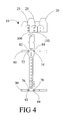
FIG. 4 is a rear view of an adjustable multi-level archery quiver where a quiver hood and arrow grippers are indexed to create a left hand quiver in accordance with the present invention.
FIG. 5 is an exploded rear view of an adjustable multi-level archery quiver, illustrating the adjustability of a quiver hood and arrow grippers relative to a frame for a right hand configuration in accordance with the present invention.
FIG. 6 is a rear view of an adjustable multi-level archery quiver where a quiver hood is indexed to create a right hand quiver in accordance with the present invention.
DETAILED DESCRIPTION OF THE PREFERRED EMBODIMENTS
FIGS. 1-6 show an adjustable multi-level archery quiver 10. The adjustable multi-level archery quiver 10 preferably includes a quiver hood 20, a frame 70, a first arrow gripper 80 and a second arrow gripper 90. However, the adjustable multi-level quiver 10 may be constructed with only one arrow gripper 90. With reference to FIGS. 1-2, the first and second arrow grippers 80, 90 include a plurality of arrow pockets 85 for retaining a shaft 35 of arrows 30, 40, 50 and 60. The shafts 35 of the arrows 30, 40, 50, 60 each include a first end and a second end. The first end of the shaft 35 engages a bow string, and broad heads 32, 42, 52, 62 are secured to the second end of the shaft 35.
With reference to FIG. 1A, the quiver hood 20 includes broad head cavities 22, 24, 26, 28. The broad head cavities 22, 24, 26, 28 are at an alternative coordinate on the Y plane. Rotation paths 34, 44, 54, 64 illustrate overlapping and intersecting paths of the broad heads 32, 42, 52, 62. If the depths of adjacent broad head cavities 22, 24, 26, 28 were not staggered as shown in FIG. 1, the broad heads 32, 42, 52, 62 could not be rotated. With reference to FIGS. 3b-3c , a staggered quiver hood 21 includes broad head cavities 33, 35, 37. It is preferable that there be an odd number of broad head cavities. The staggered quiver hood 21 is disclosed with three broad head cavities, but could be 4, 5, 6, 7, 8, 9 or etc. A center of the broad head cavities 33 and 37 are offset from a center of the broadhead cavity 35 by a distance on the “Z” axis. A depth of broad head cavity 35 is also greater than broad head cavities 33 and 37 by a distance on the “Y” axis. The offset center and different depth of the broad head cavities allow the centers of the broad head cavities 33, 35, 37 to be moved closer to each other on the “X” axis, thus allowing for a smaller foot print or for more one or two more broad heads to be contained in the staggered quiver hood 21.
With reference to FIG. 3, the frame 70 includes a first hood mounting leg 100 and a second hood mounting leg 110 located on one end. Hood mounting holes 102, 104 are located in the first hood mounting leg 100 and hood mounting holes 112, 114 are located in the second mounting leg 110. With reference to FIG. 3A, the quiver hood 20 includes a first frame mounting opening 23, a second frame mounting opening 25, and a third frame mounting opening 27. A first set of gripper mounting holes 72 and 74 are formed in substantially a middle of the frame 70. A second set of gripper mounting holes 76, 78 are formed in an opposing end of the frame 20. First gripper holes 82, 84, 86 are formed through the first arrow gripper 80 and second arrow holes 92, 94, 96 are formed through the second arrow gripper 90.
FIG. 4 discloses an assembled adjustable multi-level arrow quiver 10, where the quiver hood 20, the first arrow gripper 80, and the second arrow gripper 90 are attached to the frame 70 to create a left hand quiver. The first arrow gripper 80 is attached to the frame 70 by aligning the first gripper holes 82, 84 of the first arrow gripper 80 with the first set of gripper mounting holes 72 and 74 of the frame 70 and inserting and securing the first arrow gripper 80 with a plurality of fasteners. However, the first arrow gripper 80 may be attached to the frame 70 with any suitable method. The second arrow gripper 90 is attached to the frame 70 by aligning the second gripper holes 92, 94 of the second arrow gripper 90 with the second set of gripper mounting holes 76 and 78 of the frame 70 and inserting and securing the second arrow gripper 90 with a plurality of fasteners. However, the second arrow gripper 90 may be attached to the frame 70 with any suitable method. The first and second hood mounting legs 100, 110 are inserted through the first and second frame mounting cavities 23, 25 and attached to the first and second hood mounting legs 100, 110 with a plurality of fasteners or any other suitable attachment method.
FIG. 5 is an exploded rear view of the adjustable multi-level archery quiver 10, illustrating the adjustability of the quiver hood 20, and the first and second arrow grippers 80, 90 relative to the frame 70 to create a right hand quiver. FIG. 6 discloses an assembled adjustable multi-level arrow quiver 10, where the quiver hood 20, the first arrow gripper 80, and the second arrow gripper 90 are attached to the frame 70 to create the right hand quiver. The first arrow gripper 80 is attached to the frame 70 by aligning the first gripper holes 84, 86 of the first arrow gripper 80 with the first set of gripper mounting holes 72 and 74 of the frame 70 and inserting and securing the first arrow gripper 80 with a plurality of fasteners. However, the first arrow gripper 80 may be attached to the frame 70 with any other suitable method. The second arrow gripper 90 is attached to the frame 70 by aligning the second gripper holes 94, 96 of the second arrow gripper 90 with the second set of gripper mounting holes 76 and 78 of the frame 70 and inserting and securing the second arrow gripper 90 with a plurality of fasteners. However, the second arrow gripper 90 may be attached to the frame 70 with any other suitable method. The first and second hood mounting legs 100, 110 are inserted through the first and second frame mounting cavities 25, 27 and attached to the first and second hood mounting legs 100, 110 with a plurality of fasteners or any other suitable attachment method.
Although the figures in this application illustrate a preferred embodiment of the present invention, alternative designs may be accomplished by altering the X, Y, and Z locations of the arrows, and designing the quiver hood and arrow grippers accordingly.
While particular embodiments of the invention have been shown and described, it will be obvious to those skilled in the art that changes and modifications may be made without departing from the invention in its broader aspects, and therefore, the aim in the appended claims is to cover all such changes and modifications as fall within the true spirit and scope of the invention.