US937085A - Harvester attachment. - Google Patents
Harvester attachment. Download PDFInfo
- Publication number
- US937085A US937085A US47382709A US1909473827A US937085A US 937085 A US937085 A US 937085A US 47382709 A US47382709 A US 47382709A US 1909473827 A US1909473827 A US 1909473827A US 937085 A US937085 A US 937085A
- Authority
- US
- United States
- Prior art keywords
- divider
- wheel
- spindle
- rods
- disk
- Prior art date
- Legal status (The legal status is an assumption and is not a legal conclusion. Google has not performed a legal analysis and makes no representation as to the accuracy of the status listed.)
- Expired - Lifetime
Links
- 244000025254 Cannabis sativa Species 0.000 description 4
- 241001124569 Lycaenidae Species 0.000 description 1
- 241001465754 Metazoa Species 0.000 description 1
- 244000100170 Phaseolus lunatus Species 0.000 description 1
- 238000010276 construction Methods 0.000 description 1
- 238000006073 displacement reaction Methods 0.000 description 1
- 238000004519 manufacturing process Methods 0.000 description 1
- 230000002093 peripheral effect Effects 0.000 description 1
Images
Classifications
-
- A—HUMAN NECESSITIES
- A01—AGRICULTURE; FORESTRY; ANIMAL HUSBANDRY; HUNTING; TRAPPING; FISHING
- A01D—HARVESTING; MOWING
- A01D63/00—Outside dividers
- A01D63/02—Rotating dividers
Definitions
- MICHAEL MOLITOR or CALVARY, WISCONSIN.
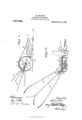
- Figure 1 represents a side elevation of a divider having attached thereto a track clearing device embodying the features of my invention, parts being broken away and parts in section to better illustrate the structural features
- Fig. 2 a plan view of the same, as indicated by line 2-2 of the preceding figure.
- 1 indicates a portion of a finger-bar, which carries the usual guard-fingers and cuttingapparatus of a mower, the finger-bar being seated in and secured to an outer divider 2, by means of a single bolt 3, as shown.
- the rearward vertical blade portion 4: of the divider is slightly offset from the body thereof and is circular in contour, being provided with a guard-flange 5 upon its upper periphery, which flange extends to the forward end of said divider.
- a disk 6 which disk has a hub 7 projecting therefrom at an angle to its face, and is adapted to fit within a peripheral recess 45* of the blade-portion 4, whereby the disk and its hub are held against vertical displacement.
- This sleeve constitutes a bearing for the hub of a traction-wheel 9, which wheel is secured thereto by a bolt 8', the wheel being formed with a lagged treadflange 10 that extends inwardly and terminates adjacent to the face of the divider blade.
- housing for a bevel pinion 11 that meshes with a bevel gear-wheel 12 forming part of the traction-wheel, the bevel-pinion being fast on a spindle l1 mounted in the diskhub 7.
- a collar 13 fast on the spindle prevents end-play thereof in its bearing and extending outwardly from the collar is a squared shank, upon which squared shank is fitted a series of eyes 14 having squared apertures corresponding to the squared shank of the spindle.
- Each eye forms part of a rod 15 that is flared outwardly therefrom, and together these rods constitute a skeleton cone shaped figure about the axis of the shank, the free ends of the rods being curved in the opposite direction from that which they are designed to revolve, whereby the grain or material in which they operate will not be caught or entangled by said ends as they engage the latter. All of the eye-portions of the rods are held in clamped position upon the squared shank, by a suitable nut, which nut is in threaded engagement with a correspondingly threaded'end of said shank.
- ne or more guard-strips 16 may be attached to the divider as shown, to protect the traction-wheel 9 from catching in the 'material and also serving to further divide the fallen grain from that which is standing, these strips however are common in the art and form no part of my invention.
- guard-flange 5 of the divider also extends partly around and over the tractionwheel to protect the same from the material being cut.
- the tread flange thus constitutes a of substituting sets of rods, whose lengths are determined by the work to be performed and the nature of the material to be cut. It will also be observed that the axis of the bevel-pinion is at such an angle to the wheelaxis, that the flared rods, which together form a reel, project diagonally across the path of travel of the cutting-mechanism of the mower and rearward of same, this angle being more or less optional and depends upon the nature of the work required and the width of the track desired to be cleared.
- the parts are rendered more simple in their manufacture and also facilitates alinement and mesh of the gearing, the recess in the circular bladeportion 4 being designed to engage and prevent turning of the disk, while the lags upon the tread of the wheel prevent the latter from slipping under the driving strain required to impart positive rotation to the reel.
- the divider as a whole is manufactured and arranged, as shown, to be attached to various standard makes of mowers, by a single bolt, the attachment being efi'ected in so simple a manner as not to require the assistance of a skilled mechanic.
- An attachment for harvesters comprising an outer divider attachable to the harvester finger-bar, a stud extending from the divider, a disk fitted over the stud, the disk being provided with a bearing-hub at an angle to the stud, a spindle mounted in the disk-hub provided with a squared shank extension, a bevel pinion secured to one end of the spindle, rods having squared apertured ends fitted over the squared shank extension of the spindle, the rods forming a skeleton-cone with relation to the spindle axis, a traction-wheel mounted upon said stud provided with a flanged tread, and an internal bevel-wheel in connection with the traction-wheel for engagement with the bevel-pinion of the spindle.
Landscapes
- Life Sciences & Earth Sciences (AREA)
- Environmental Sciences (AREA)
- Harvester Elements (AREA)
Description
Patented Oct. 19, 1909.
M. MOLITOR. HARVESTER ATTAUHMENT. APPLICATION FILED JAN. 23, 1909.
ANDREW. a. Gmum cm. HIDTO-LIYHOGRAPHERS. wAsmNuwu. a. a
UNITED STATlligli TENT OFFICE.
MICHAEL MOLITOR, or CALVARY, WISCONSIN.
HARVESTER ATTACHMENT.
Specification of Letters Patent.
Patented Oct. 19, 1909.
Application filed January 23, 1909. Serial No. 473,827.
' vesters of the mower-type, whereby cut grain or grass of the swath adjacent that which is standing is cleared therefromand formed into a windrow at a sufficient distance from the standing material, so that upon the next cutof the mower there is an unobstructed path in which the draft animal can travel and at the same time the clearing prevents the inner-shoe, which carries the cutting apparatus, from chucking or delivering the already cut material to the knives. The construction and arrangementof the attachment are such that the aforesaid clearing is effected by a reel, comprising a series of positively driven rods carried by a spindle, which spindle is in bevel-gear connection with a traction-wheel in coimection with the outside shoe or divider of the mower.
The invention therefore consists in various structural features and combination of parts as hereinafter set forth with reference to the accompanying drawings and 'subsequently claimed.
In the drawings: Figure 1 represents a side elevation of a divider having attached thereto a track clearing device embodying the features of my invention, parts being broken away and parts in section to better illustrate the structural features, and Fig. 2, a plan view of the same, as indicated by line 2-2 of the preceding figure.
Referring by numerals to the drawings, 1 indicates a portion of a finger-bar, which carries the usual guard-fingers and cuttingapparatus of a mower, the finger-bar being seated in and secured to an outer divider 2, by means of a single bolt 3, as shown. The rearward vertical blade portion 4: of the divider is slightly offset from the body thereof and is circular in contour, being provided with a guard-flange 5 upon its upper periphery, which flange extends to the forward end of said divider. Loosely fitted to the outer face of the circular blade-portion 4 of the divider, is a disk 6, which disk has a hub 7 projecting therefrom at an angle to its face, and is adapted to fit within a peripheral recess 45* of the blade-portion 4, whereby the disk and its hub are held against vertical displacement. is centrally apertured and supported upon a sleeve 8 extending from the blade-portion of the divider and concentric with its circular end. This sleeve constitutes a bearing for the hub of a traction-wheel 9, which wheel is secured thereto by a bolt 8', the wheel being formed with a lagged treadflange 10 that extends inwardly and terminates adjacent to the face of the divider blade. housing for a bevel pinion 11 that meshes with a bevel gear-wheel 12 forming part of the traction-wheel, the bevel-pinion being fast on a spindle l1 mounted in the diskhub 7. I
A collar 13 fast on the spindle prevents end-play thereof in its bearing and extending outwardly from the collar is a squared shank, upon which squared shank is fitted a series of eyes 14 having squared apertures corresponding to the squared shank of the spindle. Each eye forms part of a rod 15 that is flared outwardly therefrom, and together these rods constitute a skeleton cone shaped figure about the axis of the shank, the free ends of the rods being curved in the opposite direction from that which they are designed to revolve, whereby the grain or material in which they operate will not be caught or entangled by said ends as they engage the latter. All of the eye-portions of the rods are held in clamped position upon the squared shank, by a suitable nut, which nut is in threaded engagement with a correspondingly threaded'end of said shank.
ne or more guard-strips 16 may be attached to the divider as shown, to protect the traction-wheel 9 from catching in the 'material and also serving to further divide the fallen grain from that which is standing, these strips however are common in the art and form no part of my invention. The
guard-flange 5 of the divider, as shown, also extends partly around and over the tractionwheel to protect the same from the material being cut.
By employing the described fastening means for the rods 15 in connection with the spindle shank, it will be seen that the same may readily be detached for the purpose The disk 6 The tread flange thus constitutes a of substituting sets of rods, whose lengths are determined by the work to be performed and the nature of the material to be cut. It will also be observed that the axis of the bevel-pinion is at such an angle to the wheelaxis, that the flared rods, which together form a reel, project diagonally across the path of travel of the cutting-mechanism of the mower and rearward of same, this angle being more or less optional and depends upon the nature of the work required and the width of the track desired to be cleared.
By constructing the disk (5 and its hub detachable from the divider, the parts are rendered more simple in their manufacture and also facilitates alinement and mesh of the gearing, the recess in the circular bladeportion 4 being designed to engage and prevent turning of the disk, while the lags upon the tread of the wheel prevent the latter from slipping under the driving strain required to impart positive rotation to the reel. The divider as a whole is manufactured and arranged, as shown, to be attached to various standard makes of mowers, by a single bolt, the attachment being efi'ected in so simple a manner as not to require the assistance of a skilled mechanic.
From the foregoing it is evident that when the machine is in operation, the cut grain or grass in the line of travel of the reel will be caught by the same and be rolled or thrown into a windrow as it is shed from the revolving reel rod ends, the revolution of which wheel can not be stopped owing to the volume of grass, due to the fact that said reel is positively rotated by motion transmitted thereto from the traction-wheel. Thus a clear track adjacent to the standing grain or grass is obtained, whereby the work is materially facilitated.
I claim:
An attachment for harvesters, comprising an outer divider attachable to the harvester finger-bar, a stud extending from the divider, a disk fitted over the stud, the disk being provided with a bearing-hub at an angle to the stud, a spindle mounted in the disk-hub provided with a squared shank extension, a bevel pinion secured to one end of the spindle, rods having squared apertured ends fitted over the squared shank extension of the spindle, the rods forming a skeleton-cone with relation to the spindle axis, a traction-wheel mounted upon said stud provided with a flanged tread, and an internal bevel-wheel in connection with the traction-wheel for engagement with the bevel-pinion of the spindle.
In testimony that I claim the foregoing I have hereunto set my hand at Calvary in the county of Fond du Lac and State of Viscousin in the presence of two witnesses.
MICHAEL MOLITO R.
Vitnesses JOHN L. BEAN, JOHN IIILLEBRAND.
Priority Applications (1)
| Application Number | Priority Date | Filing Date | Title |
|---|---|---|---|
| US47382709A US937085A (en) | 1909-01-23 | 1909-01-23 | Harvester attachment. |
Applications Claiming Priority (1)
| Application Number | Priority Date | Filing Date | Title |
|---|---|---|---|
| US47382709A US937085A (en) | 1909-01-23 | 1909-01-23 | Harvester attachment. |
Publications (1)
| Publication Number | Publication Date |
|---|---|
| US937085A true US937085A (en) | 1909-10-19 |
Family
ID=3005506
Family Applications (1)
| Application Number | Title | Priority Date | Filing Date |
|---|---|---|---|
| US47382709A Expired - Lifetime US937085A (en) | 1909-01-23 | 1909-01-23 | Harvester attachment. |
Country Status (1)
| Country | Link |
|---|---|
| US (1) | US937085A (en) |
-
1909
- 1909-01-23 US US47382709A patent/US937085A/en not_active Expired - Lifetime
Similar Documents
| Publication | Publication Date | Title |
|---|---|---|
| US12213403B2 (en) | String trimmer head and spool | |
| US4283905A (en) | Mowing machine | |
| US1130283A (en) | Lawn-mower. | |
| US431836A (en) | Cutting attachment for lawn-mowers | |
| US1275851A (en) | Lawn-mower. | |
| CN204860196U (en) | Chaff cutter | |
| US1394351A (en) | Lawn-mower | |
| US162082A (en) | Improvement in mowing-machines | |
| US362516A (en) | Ehode island | |
| US876637A (en) | Mower. | |
| US296759A (en) | Lawn-mower | |
| US1971866A (en) | Rotary divider for grain harvesting machines | |
| US1256700A (en) | Grass-guard for mowers. | |
| US856940A (en) | Lawn-trimming machine. | |
| US23618A (en) | Improvement in harvesters | |
| US328145A (en) | Ments | |
| US40876A (en) | Improvement in combined rake and reel for harvesters | |
| US355234A (en) | Gilbert e | |
| US85274A (en) | Improvement in harvesters | |
| US32736A (en) | Improvement in harvesting-machines | |
| US859964A (en) | Grain-guard. | |
| US796986A (en) | Lawn-mower. | |
| US137351A (en) | Improvement in track-clearers for harvesters | |
| CA2078078A1 (en) | Mower | |
| US372068A (en) | Harvester-reel |