US936840A - Electric insulator. - Google Patents
Electric insulator. Download PDFInfo
- Publication number
- US936840A US936840A US48929409A US1909489294A US936840A US 936840 A US936840 A US 936840A US 48929409 A US48929409 A US 48929409A US 1909489294 A US1909489294 A US 1909489294A US 936840 A US936840 A US 936840A
- Authority
- US
- United States
- Prior art keywords
- insulating
- nipple
- flange
- electric insulator
- ring
- Prior art date
- Legal status (The legal status is an assumption and is not a legal conclusion. Google has not performed a legal analysis and makes no representation as to the accuracy of the status listed.)
- Expired - Lifetime
Links
- 239000003989 dielectric material Substances 0.000 title description 3
- 210000002445 nipple Anatomy 0.000 description 11
- 150000001875 compounds Chemical class 0.000 description 2
- 239000012212 insulator Substances 0.000 description 2
- 239000007788 liquid Substances 0.000 description 1
- 239000010445 mica Substances 0.000 description 1
- 229910052618 mica group Inorganic materials 0.000 description 1
- 238000012856 packing Methods 0.000 description 1
Images
Classifications
-
- F—MECHANICAL ENGINEERING; LIGHTING; HEATING; WEAPONS; BLASTING
- F16—ENGINEERING ELEMENTS AND UNITS; GENERAL MEASURES FOR PRODUCING AND MAINTAINING EFFECTIVE FUNCTIONING OF MACHINES OR INSTALLATIONS; THERMAL INSULATION IN GENERAL
- F16L—PIPES; JOINTS OR FITTINGS FOR PIPES; SUPPORTS FOR PIPES, CABLES OR PROTECTIVE TUBING; MEANS FOR THERMAL INSULATION IN GENERAL
- F16L25/00—Construction or details of pipe joints not provided for in, or of interest apart from, groups F16L13/00 - F16L23/00
- F16L25/02—Construction or details of pipe joints not provided for in, or of interest apart from, groups F16L13/00 - F16L23/00 specially adapted for electrically insulating the two pipe ends of the joint from each other
- F16L25/026—Construction or details of pipe joints not provided for in, or of interest apart from, groups F16L13/00 - F16L23/00 specially adapted for electrically insulating the two pipe ends of the joint from each other for flanged joints
Definitions
- This invention relates to electric insulators.
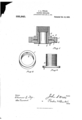
- Figure l is a sectional elevation.
- Fig. 2 is a perspective of the external ring.
- Fig. 3 is an elevation of the central nipple.
- An outer member comprising the ring 1 is provided with a flange or interior collar 2-, which extends into the chamber of the ring.
- Concentric with the ring 1 is a nipple 3, provided with a flange 4 and threaded exteriorly; with this is connected a nipple 5, provided with a flange 6, and this nipple is threaded interiorly.
- the two nipples comprise the inner holding member.
- An insulating block 7 of mica is shaped to engage on the flange 2, and to engage closely against the inner wall of the ring 1.
- the space between the insulating blocks 7 and 8 is filled with any insulating compound 9, preferably some preparation of wax or asphaltun1,'or any similar insulating compound that can be put in place in a liquid, or pliable condition, and which will fill the space between the two blocks 7 and 8.
- any insulating compound 9 preferably some preparation of wax or asphaltun1,'or any similar insulating compound that can be put in place in a liquid, or pliable condition, and which will fill the space between the two blocks 7 and 8.
- the inner nipple 3 engages through circular openings in the blocks 7 and 8 with the flange 4 bearing against the outer surface of the block 7.
- the nipple 5 is then run onto the nipple 3 untilthe flange 6 bears against the outer surface of the block 8, and the parts are thus all secured in place with the insulating packing held securely in place, and the insulating disks serve to hold the metallic parts in their proper position.
- an insulating joint the combination of an annular member provided with an inwardly projecting flange intermediate its top and bottom edges, insulating members arranged within said annular member on each side of said flange, the inner edges thereof extending nearer to the central axis than the inner edge of said flange, an externally threaded nipple, having one end flanged, engaging through said annular members with its flanged end engaging over a portion of the exposed face of one of said insulating members, and an internally threaded nipple adapted to engage over said first named nipple on the other side of the annular member and against the other one of said insulating members, substantially as described.
Landscapes
- Engineering & Computer Science (AREA)
- General Engineering & Computer Science (AREA)
- Mechanical Engineering (AREA)
- Installation Of Bus-Bars (AREA)
Description
J; A. WELLS. ELECTRIC INSULATOR.
APPLICATION FILED APR. 12, 1909.
Patented Oct. 12,1909.
, "I l/l/I k z dluummr we,
Allan-lugs mimrssrs not Pkowunlomuwms. wasmaomn. 11 Q JOHN A. WELLS, OF DETROIT, MICHIGAN.
ELECTRIC INSULATOR.
Specification of Letters Patent.
Patented Oct. 12, 1909.
Application filed April 12, 1909. Serial No. 489,294.
To all whom it may concern:
Be it known that I, JOHN A. WELLS, a citizen of the United States, residing at Detroit, county of WVayne, State of Michigan, have invented a certain new and useful Improvement in Electric Insulators, and declare the following to be a full, clear, and exact description of the same, such as will enable others skilled in the art to which it pertains to make and use the same, reference being had to the accompanying drawings, which form a part of this specification.
This invention relates to electric insulators.
It has for its object an improved insulating connection between an outer and aninner conduit, the special object of the connection being to produce an insulating joint to be used in hanging chandeliers, gas fixtures, combination fixtures, and similar connections.
In the drawings :Figure l, is a sectional elevation. Fig. 2, is a perspective of the external ring. Fig. 3, is an elevation of the central nipple.
An outer member comprising the ring 1 is provided with a flange or interior collar 2-, which extends into the chamber of the ring. Concentric with the ring 1 is a nipple 3, provided with a flange 4 and threaded exteriorly; with this is connected a nipple 5, provided with a flange 6, and this nipple is threaded interiorly. The two nipples comprise the inner holding member. An insulating block 7 of mica is shaped to engage on the flange 2, and to engage closely against the inner wall of the ring 1. An insulating block 8, similarly formed, engages on the collar 2, and within the interior of the ring 1. The space between the insulating blocks 7 and 8 is filled with any insulating compound 9, preferably some preparation of wax or asphaltun1,'or any similar insulating compound that can be put in place in a liquid, or pliable condition, and which will fill the space between the two blocks 7 and 8.
The inner nipple 3 engages through circular openings in the blocks 7 and 8 with the flange 4 bearing against the outer surface of the block 7. The nipple 5 is then run onto the nipple 3 untilthe flange 6 bears against the outer surface of the block 8, and the parts are thus all secured in place with the insulating packing held securely in place, and the insulating disks serve to hold the metallic parts in their proper position.
What I claim is In an insulating joint, the combination of an annular member provided with an inwardly projecting flange intermediate its top and bottom edges, insulating members arranged within said annular member on each side of said flange, the inner edges thereof extending nearer to the central axis than the inner edge of said flange, an externally threaded nipple, having one end flanged, engaging through said annular members with its flanged end engaging over a portion of the exposed face of one of said insulating members, and an internally threaded nipple adapted to engage over said first named nipple on the other side of the annular member and against the other one of said insulating members, substantially as described.
In testimony whereof, I sign this specification in the presence of two witnesses.
JOHN A. WELLS. Witnesses:
ALICE TOWNSEND, WILLIAM M. SWAN.
Priority Applications (1)
| Application Number | Priority Date | Filing Date | Title |
|---|---|---|---|
| US48929409A US936840A (en) | 1909-04-12 | 1909-04-12 | Electric insulator. |
Applications Claiming Priority (1)
| Application Number | Priority Date | Filing Date | Title |
|---|---|---|---|
| US48929409A US936840A (en) | 1909-04-12 | 1909-04-12 | Electric insulator. |
Publications (1)
| Publication Number | Publication Date |
|---|---|
| US936840A true US936840A (en) | 1909-10-12 |
Family
ID=3005261
Family Applications (1)
| Application Number | Title | Priority Date | Filing Date |
|---|---|---|---|
| US48929409A Expired - Lifetime US936840A (en) | 1909-04-12 | 1909-04-12 | Electric insulator. |
Country Status (1)
| Country | Link |
|---|---|
| US (1) | US936840A (en) |
Cited By (1)
| Publication number | Priority date | Publication date | Assignee | Title |
|---|---|---|---|---|
| US2950928A (en) * | 1957-12-17 | 1960-08-30 | Mueller Co | Insulated pipe joint |
-
1909
- 1909-04-12 US US48929409A patent/US936840A/en not_active Expired - Lifetime
Cited By (1)
| Publication number | Priority date | Publication date | Assignee | Title |
|---|---|---|---|---|
| US2950928A (en) * | 1957-12-17 | 1960-08-30 | Mueller Co | Insulated pipe joint |
Similar Documents
| Publication | Publication Date | Title |
|---|---|---|
| KR20160059389A (en) | Gasket | |
| US426121A (en) | Emil f | |
| US502038A (en) | Pipe-coupling | |
| US1393075A (en) | Electric-light fitting | |
| US1179808A (en) | Slip-joint floor-flange for supply-pipes. | |
| US487846A (en) | Casing for bases of incandescent lamps | |
| US722979A (en) | Electric socket and receptacle attachment. | |
| US488946A (en) | James a | |
| US554394A (en) | Insulating-joint | |
| US602564A (en) | Insulated pipe-coupling | |
| US1180838A (en) | Electric-conduit fitting. | |
| US1236594A (en) | Illuminating appliance. | |
| USD49695S (en) | Design for a forty-five-degree flat elbow-cover for fittings for elec | |
| US350355A (en) | Insulating-coupling for combined electric-light and gas fixtures | |
| US1162974A (en) | Incandescent-electric-lamp fixture. | |
| US1130255A (en) | Vacuum-bottle. | |
| US443530A (en) | Charles a | |
| US1218201A (en) | Soil-pipe-sealing device for closet-bowls and the like. | |
| US1142819A (en) | Cap for lamp-sockets and the like. | |
| USD38460S (en) | Design for a portable standard for lighting-fixtures | |
| GB191007475A (en) | A Grooved Bottom Dish for Photographic Purposes. | |
| USD49686S (en) | Design for a right-hand-twisted elbow-base for fittings for electrical | |
| US1017267A (en) | Electric-light fixture. | |
| USD49862S (en) | Electbic | |
| USD40727S (en) | Jacob k |