US936677A - Apparatus for utilizing energy derived from explosions. - Google Patents
Apparatus for utilizing energy derived from explosions. Download PDFInfo
- Publication number
- US936677A US936677A US21811504A US1904218115A US936677A US 936677 A US936677 A US 936677A US 21811504 A US21811504 A US 21811504A US 1904218115 A US1904218115 A US 1904218115A US 936677 A US936677 A US 936677A
- Authority
- US
- United States
- Prior art keywords
- chamber
- air
- pipe
- explosion
- piston
- Prior art date
- Legal status (The legal status is an assumption and is not a legal conclusion. Google has not performed a legal analysis and makes no representation as to the accuracy of the status listed.)
- Expired - Lifetime
Links
- 238000004880 explosion Methods 0.000 title description 69
- XLYOFNOQVPJJNP-UHFFFAOYSA-N water Substances O XLYOFNOQVPJJNP-UHFFFAOYSA-N 0.000 description 58
- 239000007788 liquid Substances 0.000 description 30
- 239000000446 fuel Substances 0.000 description 27
- 239000002360 explosive Substances 0.000 description 26
- 208000028659 discharge Diseases 0.000 description 13
- 239000012530 fluid Substances 0.000 description 11
- 239000000463 material Substances 0.000 description 8
- 238000004891 communication Methods 0.000 description 7
- 230000009471 action Effects 0.000 description 6
- 239000007789 gas Substances 0.000 description 6
- 239000002828 fuel tank Substances 0.000 description 5
- 230000001174 ascending effect Effects 0.000 description 4
- 238000010276 construction Methods 0.000 description 4
- 239000000203 mixture Substances 0.000 description 4
- 230000008859 change Effects 0.000 description 3
- 238000006243 chemical reaction Methods 0.000 description 3
- 230000005484 gravity Effects 0.000 description 3
- 238000010438 heat treatment Methods 0.000 description 3
- 230000000630 rising effect Effects 0.000 description 3
- 239000004215 Carbon black (E152) Substances 0.000 description 2
- 230000008878 coupling Effects 0.000 description 2
- 238000010168 coupling process Methods 0.000 description 2
- 238000005859 coupling reaction Methods 0.000 description 2
- 238000007599 discharging Methods 0.000 description 2
- 210000003414 extremity Anatomy 0.000 description 2
- 229930195733 hydrocarbon Natural products 0.000 description 2
- 150000002430 hydrocarbons Chemical class 0.000 description 2
- 150000002500 ions Chemical class 0.000 description 2
- QCUPYFTWJOZAOB-HWKANZROSA-N (e)-n-carbamoyl-2-ethylbut-2-enamide Chemical compound CC\C(=C/C)C(=O)NC(N)=O QCUPYFTWJOZAOB-HWKANZROSA-N 0.000 description 1
- 241000272522 Anas Species 0.000 description 1
- 241000370685 Arge Species 0.000 description 1
- 101100536354 Drosophila melanogaster tant gene Proteins 0.000 description 1
- 125000002059 L-arginyl group Chemical group O=C([*])[C@](N([H])[H])([H])C([H])([H])C([H])([H])C([H])([H])N([H])C(=N[H])N([H])[H] 0.000 description 1
- 241000528415 Moana Species 0.000 description 1
- 230000002411 adverse Effects 0.000 description 1
- 150000001768 cations Chemical class 0.000 description 1
- 230000002301 combined effect Effects 0.000 description 1
- 230000001419 dependent effect Effects 0.000 description 1
- 238000006073 displacement reaction Methods 0.000 description 1
- 230000000694 effects Effects 0.000 description 1
- 230000008030 elimination Effects 0.000 description 1
- 238000003379 elimination reaction Methods 0.000 description 1
- 210000003141 lower extremity Anatomy 0.000 description 1
- 238000000034 method Methods 0.000 description 1
- 230000010355 oscillation Effects 0.000 description 1
- 230000008439 repair process Effects 0.000 description 1
- 230000035939 shock Effects 0.000 description 1
- 239000007921 spray Substances 0.000 description 1
- 235000012976 tarts Nutrition 0.000 description 1
- 230000001131 transforming effect Effects 0.000 description 1
- 230000008016 vaporization Effects 0.000 description 1
- 239000002699 waste material Substances 0.000 description 1
Images
Classifications
-
- F—MECHANICAL ENGINEERING; LIGHTING; HEATING; WEAPONS; BLASTING
- F02—COMBUSTION ENGINES; HOT-GAS OR COMBUSTION-PRODUCT ENGINE PLANTS
- F02B—INTERNAL-COMBUSTION PISTON ENGINES; COMBUSTION ENGINES IN GENERAL
- F02B63/00—Adaptations of engines for driving pumps, hand-held tools or electric generators; Portable combinations of engines with engine-driven devices
- F02B63/06—Adaptations of engines for driving pumps, hand-held tools or electric generators; Portable combinations of engines with engine-driven devices for pumps
Definitions
- the apparatus be so constructed as to present the least possible obstruction and deviation in the path of its motion.
- the apparatus used herein to illustrate the invention is for lifting or moving water.
- the mechanical devices to control the operative functions and the movement of the material operated upon natu- 1all ⁇ ' ⁇ vonld take the form of valves.
- the de sirable elimination ⁇ suggested would consequently be the omission of some or all of the water controlling' valves. This therefore may hc stated t'o be one of the objects of the present invention.
- valves Besides its ecnliar desirability in the present form, t. e omission of valves is desirable in any pump and articularly valves beneath the water. Such) location renders valves subject to disarrangement by gravel, etc., and also makes them ditcult of access or repair. Fortunately the ualities which, under the circumstances of t e present disclosure, renders the presence of valves peculiarly undesirable, provide also, conditions which render them unnecessary. That is to say, the incompressibility and inertia of water may be utilized b proper mechanical provisions to take the p ace of valves. Further, as the operative functions in this device occupy such short spaces of time, the intervals between successive impulses are in a sense waste time, or at least, a failure to fully realize the mechanical capability of the apparatus.
- Another object therefore of ,the present invention is to provide such a construction as will permit the operative impulses to follow each other with the greatest possible rapidity.
- g- Figure 1 is a sectional elevation of the upper part; of the apparatus.
- Fig. 2 is a simllar elevation of the lower or submerged part.
- a pipe 3 of comlaratively small diameter extends from the ower part of the explosion chamber l downwardly into thelwell or other source of water supply. It may be provided with a nonco'nducting c'oi'ering. This is illustrated in the drawings las a second pipe of somewhat larger diameter surrounding it, making an annular air s ace around pi e 3 the whole of its length.
- urrounding't e pipe 3 is anas t l roofv i 10al f other pipe 4 of considerably-lai'ger diameter forming an air space or chamber.
- the upper portion of this air-chamber may wholly inclose the explosion chamber 1,01 partly, as shown in the drawings.
- - ⁇ t the lower extremity of the air chamber and preferably forming a continuation thereof is a length of pipe 5 which l designate a drive pipe.- It is. preferably of a diameter somewhat .smaller than the air chamber.
- Below the drive pipe is still another length of pipe 6 preferably closed at its lower end, constituting with pipe 5 an expansion space.
- This lower pipe 6 may be surrounded in a similar manner as pipe 3 is with a non-conducting covering.
- Pipe 6 is preferably cf smaller diameter than pipe Its bottoni is near the bottoni of pipe The upper edge of pipe 6 is adjacent to the lower opening of pipe 5-leaving an anniilai' space between the two pipes as an entranceI for water.
- Thisl part may be made, as illustrated, to constitute an injector device either by suitably ⁇ shaping the adjacent ends of these pipes or by a coupling piece 7 to which both are attached.
- Intcrposed between the pipe i and the air chamber 4 is a somewhat peculiar device 8, which I terni a splitting nozzle.
- lt is preferably of annular forni and concentric to the variousv pipes mentioned. lts internal diameter is smaller than the pipe 5 and approximates that of pipe (l. Its lower part is chamfered or sharpened inwardly to its smaller diameter, to present an annular splitting edge 9 to abody of water flowing upward through pipe
- the upper part of 8 is formed witha concave or recurved surface 10 .forming a s litting inner edge and an upwardly curve outcr edge. For constructive convenience, the s litting. nozzle is made to serve as a coupling etween the pipes 4 and 5'as shown.
- A11 opening 11 is rovided at the upper end of pipe 5 an( an opening 12 atthe lower end of pipe' 4 respectively on each side of the splitting nozzle 8. These openings are shown as holes arranged around their respective pipes.
- a ipe or casing 13 surrounds and iin-loses the a ready mentioned pipes and' serves both as a supply and a discharge pipe. In some cases, it may, as shown in the illustration, be the well casing. lts upper end may be provided with a head 1v1 having a discharge opening or elbow as shown. This head 14 may forni a base. or support for the already describen construction as shown in Fi r. 1.
- the head or gravity will consequently cause it, to enter through the annular o ening between the pipes 5 and 6 with a ve ocity due to the combined effects of the injector principle and gravity.
- the iiprushing water in 5 encounters the splittin nozzle 8 and a large amount of it separateil and deflected outward through the openings 11.
- the remaining annular core continues upward and expcnds the energy and kinetic inertia imparted to it by the explosion in compressing the .air in the air-chamber.
- This water core being of smaller diameterI than the air-chamber permits a current of water and compressed air around its exterior to be displaced and forced downward and out of the air-chamber.
- silicnt adds to the capacity of the air-chamber for ahsorbing thc energy of eX- plosion without shock to the apparatus. It may also he observed that in consequence of the nonconductin; t covcrin; r to the pipes 3 and ti, the hot gast-.s do noty come in contact with any surfaces cooled hy the water of the well till they have expanded down to a comparatively low temperature. As these air spaces around the pipes may he in free corninunication with the air-chamber. any heat. which is conveyed tlirmigh the walls Ywill reappear in work hy expam'liiipr the air' in the air-chamber.
- the arrangement of the expansion space (3 in relation to the pipe il avoids' any change in direction oi thev inert and incompressible water piston, the. unavoidable change of direction being transferred by this ⁇ construction from the pistou to the more [luid and resilient elementi, the expanding gases and air.
- somo :jimple meansl uch as a hand air pump to in- ]ect air into the column dnrinpr the first few impulsenin order to ⁇ :tart the column into motion and render it sullicientlv resilient to perform its function as a cuhhion. h'o that when the term air chamber. rehilient cushion or the like cxpiesaons are used herein, they are to be understoml to mcali either the iiiclosed chamber containingr air or merelyy the au' or other gas introduced into the water or cie diaree pipe in such forni as'to cushion the explosive blow,
- l t should be understood that the description heretofore. of the action of the gases and fluids during the operation, will vary with the proportion which the air chamber bears to the resilient column and with other variable factors, such as subniergeuce, head and position of explosion chamber with ret'- erence to the expansion chamber, etc. lty however may he stated with certainty that. in a device built. in accordance with this in ⁇ vention, the explosive gas will expand in proportion to the resistance to be overcome and a volume of water proportionate to the work expended by the. expanding gafas, will issue from the discharge aperture.
- Fig. 1 is representet'l a simple and etlective meansfor introducing liquid hydro-carbon into the explosion chamber in thc form ol' spray or vapor. and an igniting device t'or iuilamingr the resulting mixture.
- the particular object. in view in this form of introducing device that the fuel shall not he permitted to cuter the explosion chamber except when the valve 2 is closed and further thaty it shall commence to cuter practically ⁇ siniultaiieously willi the closing: of this valve.
- valve 2 is itself made to control the time for the admittance et' the vaporous fuel. This is accomplished liyproviding a longitudinal passage 16 in the stem ol' the of the valve stein as shown. This passage is provided with a suitable check valve, shown as a ball valve 17 c lesable h v pressure within the chamber 1. A circumferential groove 18 is provided in the valve stem guide communicating with passage 1t; only when the valve 2 is closed. A passage 1t) communicating Wit-h groove 18 is also provided. This passage is preferably controlled by a valve 20 as shown A mixing or vapori/.ing chamber or passage 21 is provided communicating with passage 19 and also with a source of air pressure and a liquid fuel supply by suitable valve controlled passages.
- the vaporizing' chamber 2 is connected by a pipe couti ⁇ led by a valve with an air tight i'uel tank 23. Ity is also connected with thc air chamber by a passage controlled hy a valve 2-l shown as a plug; valve in section.
- the fuel tank is connected above the level of the fuel with Ithe air chamber by a pipe or passage 25 controlled b v ay non-return valve 2G.
- Means for heating plate 2T aic represented as a Buiisen burner 2S arranged to ro eet a llame upon the platel 27. 1ty nii r it e noticed that the valve 2 is provided wit a closing spring 29 and nuts gut-he i i l l i i l i l valve 2 opening inwardly to the explo-on operations 'which have been described chamber and outwardly to the periphery repente-diudelinitely.
- this t ie device is as follows :--It shoul be understood that the pressurev in the fuel tank 23 is equal to the highest pressure attained in the air-chamber. which during the operation of th-i ⁇ device is higher than the pressure in chamber l except during the period of ex-v plosion. (if course when starting up. for the first time, or in the event of the pressure in 23 escaping, from any cause, it could be renewed h v an; of the ordinary means as for example. a hand air pump. Assuinin then pressure in 2? and the plate 27 heate the device inaybc started by merely openin tlnx valve 20.
- valveless character of the device is impor-- tant.
- a drive pipe having a chamber at each of its ends in free and uncontrolled communication therewith, said chambers being or' suitable character to contain an dastic fluidmieans for introducing into one of said chambers fuel to form a succession of explosive cha-rges, means to ignite the charges .and liquid acting as a piston in the drive pipe in advance of the charges.
- expansion chamber an unobstructed pipe ci' passage of relatively small diameter connecting the tivo chambers, a drive pipe, an air-chamber, the drive pipe and air-chainbei' being in free and uncontrolled communication with the expansion chamber and liquid in the expansion chamber acting as a piston.
- the combination in an apparatus of the named type. the combination :if an explosion chamber, an expansion chamber, an unobstructed pipe or passa e of relatively small diameter connecting t e chambers, means for introducing into the explosion chamber aii'aiid fuel and vcommingling them to form a succession of v.explosive charges, means to ignite the charges and of a freely movable body acting as av iston in the drive pipe in advance of the c ..arges. 12.
- jector device for introducing liquid, between body in the expansion chamber acting as a piston and a splitting nozzle between the being in free and uncontrolled communieaexpansion chamber a d drive pipe.
- expansion chamber au unobstructed pipe or passage of relatively small diamcterconnectg ing the two chambers, a drive pipe and an f air-chamber, the drive pipe and air-chamber l being connected by a splitting nozzle andi liquid introduced in the expansion chamber acting as a piston.
- Iii an apparatus for applying energy derived from explosion, the combination and a discharge conduit.
- an explosion chamber of means for admitting an explosive charge ther-cinto, means for igniting said charge, an expansion chamber located beneath the surface of the water, having an aperture directed substantially in the direction of desired an expansion chamber, an unobstructed pipe or passage of relatively small diameter connecting the two chambers, a freely opening valve in the'explosion chamber for the admission of air provided with a substantially' ,central opening for fuel to form an explosive charge, means to ignite the charge and liquid in the drive pipe acting as a piston.
- t yp In an apparatus of th'e named t yp", the combination with an explosion chamber, an expansion chamber, an unobstructed pipe Yor passa lfe of relatively small diameter coii- Vnecting t 1e two chambers, an inwardl opcnp ing valve in the explosion chamber for the admission of air provided with a tension device-and means for adjustin the tension of said device, means for intr ucing fuel into the explosion chamber and commingling it vwith the air therein whereby a succession of explosive charges are'formcd, means'to ignite the charges and liquid in the expansion chamber acting as a. piston.
- the combination with anexplosion chamber having a suitable igniter, an expansion chamber, an air chamber, means tor admitting water thei'cinto, a fuel tanli suitably coni uectcd with the air chamber whereby the y pressure therein forces liquid fuel into the explosion chamber to form an explosive mix tui-e therein.
- Aan apparatus of thenamed type the combination of an explosion chamber, an i expansion chamber, an unobstruc'led pipe or I'passage of relatively .small diameter provided with a nou-conducting covering,pcon necting the two chambers and liquid iii the expansion chamber acting as a piston.
- sion chamber a body of material in the expansion chamber to act. as a. piston, and an air chamber against .which the piston ext chamber.
- an apparatus ofthe named type the combination with an explosion chamber haringa suitable igniter.
- an expansion chamberl ⁇ means. for admitting water thereinto.
- an explosion chamber means for introducingl fuel thereinto.
- an igniter a pipe of relatively .small dia neter extending from the explosion cbamla r arranged and adapted to be submerged beneath the surface of water.
- an expansion chamber inclosin Y the submerged end of tht pipe and rising a ove it.
- f. lnan apparatus of the named typanthe combination with an explosion and ex'pansion chamber means for introducing fuel for compressing the .-harqo prior to i ynition, an ai; ⁇ chamber and a body of iquir acting as a piston interposed between the expansion chamlwr an'i the air chamber. a hot-surface ignitcr to the explosion chamber and means for heating the igniter.
- 3T. ln an apparatus of thenamed typethe combination with an cxploqion and expansion chamber. means: for introducing fuel thercinto to form an explosive Chargemeans for compressing the charge prior to i fnition, an air chamber and a body of liquid acting as a piston interposed between the expansion chauiln'a ⁇ and the air chamber. a hot-Surfer@ ignitcr to the explwion chavnln-r and means for iicatin'e the igniter, and a discharge pipe.
- an explosion chamber and a body of liquid actine' as a piston.
- a pipe, an aii'felianiber at each of its extremities forming' a. resilient cushion, a body or' liquid in said ipe, means for introducing fuel into one o ⁇ the chambers to form a succession of explosive charges and means for igniting the same and means for introducing and discharging successive increments of fluid and an inlet and a dis- 44.
- sion chamber acting;r as a piston, an injector nozzle, :in aii' chamber against-which the piston expe-nds its cneigy, an unobstructed pipe or passage between the injector nozzle and 46.
- the eoiiibinatien of an expansion chamber a body of fluid in the expansion chamber acting as a piston, an injector nozzle, an air chamber against which the piston expends its energy, an unobstructed pi pe or passage bctwcen the -injector nozzle and air chamber,
Landscapes
- Engineering & Computer Science (AREA)
- Chemical & Material Sciences (AREA)
- Combustion & Propulsion (AREA)
- Mechanical Engineering (AREA)
- General Engineering & Computer Science (AREA)
- Fluidized-Bed Combustion And Resonant Combustion (AREA)
Description
W. H. SMYTH. v APPARATUS rox UTILIZING ENERGY DEBIVBD non BxPLosIoNs.
APPLIOTIOB' FILED JULY 25, 1904.
Patented Ot. 12,1909.
zwen or 7T/:1. [.lfvnllll l WIIZLIAM H. SMYTH, 0F SAN FRANCISCO, CALIFORNIA.
APPARATUS FOR UTILIZING ENERGY DEBIVED FROMXPLOSIONS.
Specification of Letters Patent.
Patented Oct. 12, 1909.
Application led July 25, 1904. Serial No. 218,116.
T o all whom, 'it may concern.: y
Be it known that I, YILLIAH H. SMYTH, mechanical engineer. citizen of the United States, residing in the cit and county of San Francisco and State o California, have invented certain new and useful Improvements in Apparatus for Uiilizinpt Energy Derived from Explosions; and I do hereby declare the folloivlng to be a full, clear, and exact description of the same.
In the new type of device for the utilization of explosive energy to which the present invention relates, conditions are present, which make it. desirable to eliminate to the greatest extent possible, mechanically operated or. metallic movin r parts. As one of the fundamental objects o this type of apparatus is to transform and store up in a form available for use at` will, energy derived from successive explosions within the period of time occupied by heat conduction through metallic walls; it is apparent that if mechanical or metallic moving parts be employed 1n the operative functions, these parts will be compelled to perform their functions at extreme speeds or in periods of time measurable only in small fractions of seconds and consequently under adverse conditions. Again, as the material selected in the present expression of the invention, as the medium through the movement of which explosive energy is transformed, namely a water piston, is characterized by the qualities of incornpressibility and inertia or mass 1n a high degree, it is desirable that the apparatus be so constructed as to present the least possible obstruction and deviation in the path of its motion. As the apparatus used herein to illustrate the invention is for lifting or moving water. the mechanical devices to control the operative functions and the movement of the material operated upon natu- 1all \'\vonld take the form of valves. The de sirable elimination `suggested would consequently be the omission of some or all of the water controlling' valves. This therefore may hc stated t'o be one of the objects of the present invention.
l and an application for an apparatus of the same general type provided with submerged valves filed October 13, 1902 under the title of Utilizing heat energy, Serial No. 127,173.
Besides its ecnliar desirability in the present form, t. e omission of valves is desirable in any pump and articularly valves beneath the water. Such) location renders valves subject to disarrangement by gravel, etc., and also makes them ditcult of access or repair. Fortunately the ualities which, under the circumstances of t e present disclosure, renders the presence of valves peculiarly undesirable, provide also, conditions which render them unnecessary. That is to say, the incompressibility and inertia of water may be utilized b proper mechanical provisions to take the p ace of valves. Further, as the operative functions in this device occupy such short spaces of time, the intervals between successive impulses are in a sense waste time, or at least, a failure to fully realize the mechanical capability of the apparatus.
Another object therefore of ,the present invention is to provide such a construction as will permit the operative impulses to follow each other with the greatest possible rapidity.
These and other objects, more readily understood from a description of the apparatus and its operation than from a mere general statement, are accomplished by the devices illustrated in the accompanying drawings. i
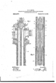
Referring to these drawings g-Figure 1 is a sectional elevation of the upper part; of the apparatus. Fig. 2 is a simllar elevation of the lower or submerged part. y
l represents an exp osion chamber provided Witl". an inwar'dly opening valve 2, also fuel controllinganld introducing devices and an ignite" all -of tvhich will be more fully described hereinafter. A pipe 3 of comlaratively small diameter extends from the ower part of the explosion chamber l downwardly into thelwell or other source of water supply. It may be provided with a nonco'nducting c'oi'ering. This is illustrated in the drawings las a second pipe of somewhat larger diameter surrounding it, making an annular air s ace around pi e 3 the whole of its length.
urrounding't e pipe 3 is anas t l roofv i 10al f other pipe 4 of considerably-lai'ger diameter forming an air space or chamber. The upper portion of this air-chamber may wholly inclose the explosion chamber 1,01 partly, as shown in the drawings. -\t the lower extremity of the air chamber and preferably forming a continuation thereof is a length of pipe 5 which l designate a drive pipe.- It is. preferably of a diameter somewhat .smaller than the air chamber. Below the drive pipe is still another length of pipe 6 preferably closed at its lower end, constituting with pipe 5 an expansion space. This lower pipe 6 may be surrounded in a similar manner as pipe 3 is with a non-conducting covering. Pipe 6 is preferably cf smaller diameter than pipe Its bottoni is near the bottoni of pipe The upper edge of pipe 6 is adjacent to the lower opening of pipe 5-leaving an anniilai' space between the two pipes as an entranceI for water. Thisl part may be made, as illustrated, to constitute an injector device either by suitably `shaping the adjacent ends of these pipes or by a coupling piece 7 to which both are attached.
Intcrposed between the pipe i and the air chamber 4 is a somewhat peculiar device 8, which I terni a splitting nozzle. lt is preferably of annular forni and concentric to the variousv pipes mentioned. lts internal diameter is smaller than the pipe 5 and approximates that of pipe (l. Its lower part is chamfered or sharpened inwardly to its smaller diameter, to present an annular splitting edge 9 to abody of water flowing upward through pipe The upper part of 8 is formed witha concave or recurved surface 10 .forming a s litting inner edge and an upwardly curve outcr edge. For constructive convenience, the s litting. nozzle is made to serve as a coupling etween the pipes 4 and 5'as shown. A11 opening 11 is rovided at the upper end of pipe 5 an( an opening 12 atthe lower end of pipe' 4 respectively on each side of the splitting nozzle 8. These openings are shown as holes arranged around their respective pipes.
A ipe or casing 13 surrounds and iin-loses the a ready mentioned pipes and' serves both as a supply and a discharge pipe. In some cases, it may, as shown in the illustration, be the well casing. lts upper end may be provided with a head 1v1 having a discharge opening or elbow as shown. This head 14 may forni a base. or support for the already describen construction as shown in Fi r. 1.
It is a convenient method to havct ie air chamber with its described attachments provided with a separate llange 15. -The exlosioirclianibei' 1 and pipe 3 also should be independently attached. By this construction which is clearly shown in Fig. 1, the various pipes etc., which are within the casing are readily and scparably removable, a matter of some practical importance.
As the cycle of this device is not essentially dependent upon any particular heat generating means, it will, l think, conduce to clearness to describe its operation before describing in detail ythe means which l pre*- fer to employ for producing and igniting explosive charges. Assuming then The de- Iwater will also have risen in the device and compressed the air in the air chamber toA the pressure due to the submergence. If now suitable hydrocarbon or other fuel be introduced into the chamber 1 in suitable volume to form with the aiif therein an explosive mixture and this be i fnited, the following described elleets will talte placez- The inflaniing gases will expand with ex-v plosive rapidity travel down the pi )c 3 drivin r the air therein before them an displace t ie water in t'- and drive it with great velocity into 5 puttin the water therein also into motion of hig speed, constituting the water in 6 and in 5 a water piston of comparatively small mass. 'The upward displacement of the water in t and 5 will rerelieve the water in the casing below the nozzle 7 of pressure. The head or gravity will consequently cause it, to enter through the annular o ening between the pipes 5 and 6 with a ve ocity due to the combined effects of the injector principle and gravity. The iiprushing water in 5 encounters the splittin nozzle 8 and a large amount of it separateil and deflected outward through the openings 11. The remaining annular core continues upward and expcnds the energy and kinetic inertia imparted to it by the explosion in compressing the .air in the air-chamber. This water core being of smaller diameterI than the air-chamber permits a current of water and compressed air around its exterior to be displaced and forced downward and out of the air-chamber. In its downward flow, this current meets the concave detlecting surface 10 and is thus deflected outward and upward assisted and accelerated by the direct action of the upflowing water separated by the lower splitting ed e. The expanding gases in 1 drive and fo low the upllowing water in 6 and 5 till the expansion pressure falls to or below atmospheric pressure. At this point, :the valve 2 o ens` increasing space om which the water has beenypnd 1s being displaced. Thusy thisnspace is filled with air at atmospheric pressure.
aperture at 7 duc to the lic-ad and its acquired kinetic inertia assisted doubtless by the uprushing atinonpheric air. The ettect of explo=ive energy having bern expended and the uprnshing water pistou hai ing heen i f ccndiupf column and renders thc column rc- 'lhe arreted by the resilient, cun'hion of the air chamber, a reaction now takea place. roiilience of the air in the air-chaiuher forces the Water therein downward throughthe nozzle 8 into 'The splitting action of the 'upper surface of S separate and defiects a portion of it outward and upward. At this time in the drive pipe 5 there is au upwardly ascending annular body of water surrounding a core of atmospheric air. This air of courf'se extends from 5 wholly tilling the spaces (i, 3 and 1. By the downward rush of the water through the nozzle 8, this air is compressed back into :l and l to a degree of coiiipresaion commensurate, with the energy ot thc reaction. 'lhe valve 2 of course closes as the irht elect of the reaction. The proportion of the chamher (i is auch that no water enters the pipe 3. Again a highly unstable equilibrium of the contending forces is reached with the water piston at the limit of its back journey and the air in l heavily compressed. The air remaining in t3 and is rapidly ascending with the water will flowing in by gravity and kinetic inertia through the entrance. At this inetant, another charge is ignited and thel cycle repeated.
t will thus be seen that a violent, but coni trolled, surging or pend uluni like oscillation of the water piaton takes place, alternately against the resiiient cushion of the air-chamber and the resilient air cushion in the charge chamber. This is a moet highly de- ,sirable condition as the piston alternately gives and receives energy with practically no loss. Thus the increments of energy due to explosive action is wholly liberated to cffect the upward movement of thc water in the casing. This upward iii\,ivement, hy the form of the apparatus, is facilitated and backward movement made to react also .in an upward direction. There is thus effected a continually ascending flow of water in the casing againat which the whoic force of t'lic explosive impulses if; expended. In consequence of the small maa@ ot the water piston, relatively tothe water in the well, it is put into violent. upward motion with practically no backward disturbance to the Vwater beneath the chamber o. lt will he. no-
silicnt and thus adds to the capacity of the air-chamber for ahsorbing thc energy of eX- plosion without shock to the apparatus. It may also he observed that in consequence of the nonconductin; t covcrin; r to the pipes 3 and ti, the hot gast-.s do noty come in contact with any surfaces cooled hy the water of the well till they have expanded down to a comparatively low temperature. As these air spaces around the pipes may he in free corninunication with the air-chamber. any heat. which is conveyed tlirmigh the walls Ywill reappear in work hy expam'liiipr the air' in the air-chamber. The arrangement of the expansion space (3 in relation to the pipe il avoids' any change in direction oi thev inert and incompressible water piston, the. unavoidable change of direction being transferred by this` construction from the pistou to the more [luid and resilient elementi, the expanding gases and air.
As stated heretofore the introduction of air into the ascending column, addsv to the capacity of the air chamber, that is to say, it serves with the air chamber as a resilient cushion lo receive the impact of the explosion. The proportion of thisv function or effeet thrown upon the resilient discharge column or upon the air chamber is left largely to the judgment of the constructor,guided by the circumstancesof the situation in whiclivthc invention is to be operated. It may he stated in this connection that .under some circumstances, it will he found that the resilientcolumn of-the discharge water will give all of the cushion that is neccsiicary to the effective working of the device so that under such circumstances. the air chamber may he entirely dispensed with. It may he found desirable when operating-.the device under these latter conditions to provide somo :jimple meansl uch as a hand air pump to in- ]ect air into the column dnrinpr the first few impulsenin order to `:tart the column into motion and render it sullicientlv resilient to perform its function as a cuhhion. h'o that when the term air chamber. rehilient cushion or the like cxpiesaons are used herein, they are to be understoml to mcali either the iiiclosed chamber containingr air or merelyy the au' or other gas introduced into the water or cie diaree pipe in such forni as'to cushion the explosive blow,
l t should be understood that the description heretofore. of the action of the gases and fluids during the operation, will vary with the proportion which the air chamber bears to the resilient column and with other variable factors, such as subniergeuce, head and position of explosion chamber with ret'- erence to the expansion chamber, etc. lty however may he stated with certainty that. in a device built. in accordance with this in` vention, the explosive gas will expand in proportion to the resistance to be overcome and a volume of water proportionate to the work expended by the. expanding gafas, will issue from the discharge aperture.
Returning nowto constructive detail; in Fig. 1 is representet'l a simple and etlective meansfor introducing liquid hydro-carbon into the explosion chamber in thc form ol' spray or vapor. and an igniting device t'or iuilamingr the resulting mixture. The particular object. in view in this form of introducing device that the fuel shall not he permitted to cuter the explosion chamber except when the valve 2 is closed and further thaty it shall commence to cuter practically `siniultaiieously willi the closing: of this valve. These requirements look toward that other and more fundamental object already referred to oi' cnrtailing the interval between the explosive impulses to its shortest ossible duration. Vith these purposes in view, the valve 2 is itself made to control the time for the admittance et' the vaporous fuel. This is accomplished liyproviding a longitudinal passage 16 in the stem ol' the of the valve stein as shown. This passage is provided with a suitable check valve, shown as a ball valve 17 c lesable h v pressure within the chamber 1. A circumferential groove 18 is provided in the valve stem guide communicating with passage 1t; only when the valve 2 is closed. A passage 1t) communicating Wit-h groove 18 is also provided. This passage is preferably controlled by a valve 20 as shown A mixing or vapori/.ing chamber or passage 21 is provided communicating with passage 19 and also with a source of air pressure and a liquid fuel supply by suitable valve controlled passages. ln the form shown, the vaporizing' chamber 2] is connected by a pipe couti `led by a valve with an air tight i'uel tank 23. Ity is also connected with thc air chamber by a passage controlled hy a valve 2-l shown as a plug; valve in section. The fuel tank is connected above the level of the fuel with Ithe air chamber by a pipe or passage 25 controlled b v ay non-return valve 2G. I have indicated an igniting-device as consistingv cfa thin sheet or plate 27 coveringr an aperture inthe. wall of the explosion chamber. Means for heating plate 2T aic represented as a Buiisen burner 2S arranged to ro eet a llame upon the platel 27. 1ty nii r it e noticed that the valve 2 is provided wit a closing spring 29 and nuts gut-he i i l l i i l i l valve 2 opening inwardly to the explo-on operations 'which have been described chamber and outwardly to the periphery repente-diudelinitely.
spring. The operation of this t ie device is as follows :--It shoul be understood that the pressurev in the fuel tank 23 is equal to the highest pressure attained in the air-chamber. which during the operation of th-i` device is higher than the pressure in chamber l except during the period of ex-v plosion. (if course when starting up. for the first time, or in the event of the pressure in 23 escaping, from any cause, it could be renewed h v an; of the ordinary means as for example. a hand air pump. Assuinin then pressure in 2? and the plate 27 heate the device inaybc started by merely openin tlnx valve 20. This permits liquid fuel an air from the tankto escape into the 'assage luid be there vaporized, and so on t rough age 15) and passage 16 to the chamber 1 where this rich vapor is mingled with the air till the combined mixture reaches explosive conditions. Itis ignited by contact with the hotl ilate and an explosion results.v The excess o pressure in chamber- 1 causes the valve 17 to close the passage'lt, and the heretofore described operations of thedevioe takes place.. As soon as the pressure reaches that of atmosphere, the valve 2 opens and consequently shuts .otl' the supply of fuel vapor until the valve 2 is again closed in the performance of its more direct function, when fuel is again admitted and the various are It will be observed that in the operation of this device, certain novel, interesting and valuable conditions and functions-are present and utilized. The first and most; striking the pendulum like or surging action of the. water piston in its unrestricted reciprocation against oppositely disposed resilient'. cushions. This utilizes and malz'es ractically effective a condition in which bo ies of large mass may be kept in motion with a minimum expenditure of energy, thus is brought about a condition .in which practically the whole of the explosive increment. of
energy is liberated for the accom lishmen/ of eicctive work or in other wor s raising the mechanical etliciencv of the transforming apparatus to practically theoretical erfection. Another condition is that. invoii'ed in the fact. that the path of the water moved is raetically without change of direction.' "rom a practical point of view also, the
valveless character of the device is impor-- tant.
As therefore this disclosure intro# duces in useful expression such broadly novel principles, functions and eiects for the utilization of the energy of explosive action and their application to the raising and mov ing of water. it is not desired that the invention be limited 'tothe forms, proportions or arrancenients ofthe parts as herein illustrate or any particular mechancaleirprg;
ist
samen'- sion thereof, but I desire to' claim the iriv'etion or inventions herein, in the broadest manner as a pioneer invention.
What I claim is 1. In an apparatus of the named type, the combination of a drive pipe having a chamber at each of its ends in free and uncontrolled communication therewith. said chanibers being of suitable character to contain an elastic Huid, means for introducing into s one of said chambers furl and commingle it with the huid therein to forni :in explosive charge, means to ignite the charge, and a freely movable body acting as a piston in they drive pipe and in advance of the charge.
2. In an apparatus of the named type, the combination of a drive pipe having a chamber at each of its ends in free and uncfrz.4
A trolled communication therewith, said chamtrolled communication therewith, said chambers being ofsuitable character to contain an elastic fluid, means for introducing into one.
' of said chambers fuel and commingle it with the fluid therein to form a succession of explosive charges, means to ignite the charges, and a freely movable bodyy acting as a piston in the drive pipe and in advance of the charges.
4. In an apparatus of the named type, the combination of a drive pipe having a chamber at each of its ends in free and uncontrolled communication therewith, said chambers being or' suitable character to contain an dastic fluidmieans for introducing into one of said chambers fuel to form a succession of explosive cha-rges, means to ignite the charges .and liquid acting as a piston in the drive pipe in advance of the charges.
o. In an apparatus of the named type, the combination of an explosion chamber, an expansion chamber, an unobstructed pipe or passage of relatively small diameter connecting the two chambers, and a freely movable body in the expansion chamber acting as a piston.
6.- In an. apparatus of the named type, the combination of an explosion chamber, an expansion chamber, an unobstructed pipe or passage of relatively small diameter connecting the tivo chambers, a drive pipe, an air-chamber, the drive pipe and air-chamber being in free and uncontrolled communication. with the es ansion chamber and a freely movable-bodluivin the expansion chainber' acting as n piston.
71 Inl an apparatus of *he named type, the
combination of :in explosion chamber, su'. expansion chamber, an unobstructed pipe or passage of relatively small diameter conl nectingthe two chambers and liquid in the i expansion chamber actingr as a piston.
8. In an apparatus of the named type. the
expansion chamber. an unobstructed pipe ci' passage of relatively small diameter connecting the tivo chambers, a drive pipe, an air-chamber, the drive pipe and air-chainbei' being in free and uncontrolled communication with the expansion chamber and liquid in the expansion chamber acting as a piston.
s In an apparatus of the named type. the i combination of an explosion chamber, an evpansion chamber, an unobstructed pipe or passage of relatively small diameter connecting the tivo chambers and means for introducing liquid in the expansion chainbei' to'act as a piston.
10.1In an apparatus of tlienamed type, 'the combination of an explosion chamber, an expansion chamber. an unobstructed pipe or passage of relativelv small diameter cfmnecting the two cham ers, a vdrive pipe, an air-chamber, the drive pipe and air-chainber being in free and uncontrolled communi- Ameans for introducing liquid in the expansion chamber to act as a piston.
l1. In an apparatus of the named type. the combination :if an explosion chamber, an expansion chamber, an unobstructed pipe or passa e of relatively small diameter connecting t e chambers, means for introducing into the explosion chamber aii'aiid fuel and vcommingling them to form a succession of v.explosive charges, means to ignite the charges and of a freely movable body acting as av iston in the drive pipe in advance of the c ..arges. 12. In an apparatus of the named type, the combination of an explosion chamber, an expansion chamber, an unobstructed pipe or pass e of relatively small diameter connecting t e chambers, means for introducing air into the explosion chamber, means for introducing fuel into the explosion chamber and commingling it with the air therein means to ignite the charges and liquid acting as a piston in the drive pipe in advance of the charges. j
v13. In an apparatus of the named type, the combination of :in explosion chamber, au expansion chamber, an unobstructed pipe or passage of relatively small diameter connecting the two chambers, and an inthe ex ansion chamber and drive pipe..
Y I4. n an apparatus of.t.he..named.type, the combination. of an explosion chamber, ani expansion chamber, an unobstructed pipe cation with theexpansion chamber and,
to form a succession of explosive charges,
ronibination of an explosion chamber. au
jector device for introducing liquid, between body in the expansion chamber acting as a piston and a splitting nozzle between the being in free and uncontrolled communieaexpansion chamber a d drive pipe.
15.' Iii an apparatus of the named type,f
the coiuhinat ion of an explosion chamber, an
expansion chamber, au unobstructed pipe or passage of relatively small diamcterconnectg ing the two chambers, a drive pipe and an f air-chamber, the drive pipe and air-chamber l being connected by a splitting nozzle andi liquid introduced in the expansion chamber acting as a piston.
16. In an apparatus of the named type,; the combination of an explosion chainberiJiy/,rir-'chaniben expansion chamber, an unobstructed pipe passage of relatively simili diameter connecting the chamber, the drive pipe and air-clialmber v tion with the expansion chamber, means for y introducing liquid in the expansion chainber, and a discharge pipe.
17. Iii an apparatus for applying energy derived from explosion, the combination and a discharge conduit.
18. In .an apparatus of the named type, l the combination with an explosion chamber,
with an explosion chamber of means for admitting an explosive charge ther-cinto, means for igniting said charge, an expansion chamber located beneath the surface of the water, having an aperture directed substantially in the direction of desired an expansion chamber, an unobstructed pipe or passage of relatively small diameter connecting the two chambers, a freely opening valve in the'explosion chamber for the admission of air provided with a substantially' ,central opening for fuel to form an explosive charge, means to ignite the charge and liquid in the drive pipe acting as a piston.
lt). In an apparatus of th'e named t yp", the combination with an explosion chamber, an expansion chamber, an unobstructed pipe Yor passa lfe of relatively small diameter coii- Vnecting t 1e two chambers, an inwardl opcnp ing valve in the explosion chamber for the admission of air provided with a tension device-and means for adjustin the tension of said device, means for intr ucing fuel into the explosion chamber and commingling it vwith the air therein whereby a succession of explosive charges are'formcd, means'to ignite the charges and liquid in the expansion chamber acting as a. piston.
20. In an apparatus of the named type, the combination with an explosion chamber, im expansion chamber, an unobstructed pipe or passage of relatively small diameter connecting the two chambers, a drive pipe conl tivo chambers, a drive pi pc, ail` aii'- llow I nected with the expansion chamber, an in wardly opening valve in the explosion cham ber for the admission of air and a passage for fuel controlled by said valve.
21. In an apparatus of the named type, the combination with anexplosion chamber having a suitable igniter, an expansion chamber, an air chamber, means tor admitting water thei'cinto, a fuel tanli suitably coni uectcd with the air chamber whereby the y pressure therein forces liquid fuel into the explosion chamber to form an explosive mix tui-e therein.
the combination of an explosion chamber, Z an expansion chamber, an unobstructed pipe or passage of vrelatively small diameter con` necting the two chambers, a'drive pipe, iii the drive pipe and air-chamber l lit-ing coiinccted by a splitting nozzle pro- 2 vided with a splitting top and bottoni edge and a curved tlctlecting upper surface and i liquid introduced in the expansion chamber acting as a piston. A In Aan apparatus of thenamed type, the combination of an explosion chamber, an i expansion chamber, an unobstruc'led pipe or I'passage of relatively .small diameter provided with a nou-conducting covering,pcon necting the two chambers and liquid iii the expansion chamber acting as a piston.
E24.V In an apparatus of the named t 'pe,
` the combination of an explosion cham l',
i an expansion chamber, an unobstructed pipe or passage of relatively small diameter connecting the two chambers, a drive pipe, an air-chamber and a splitting nozzle located with an openingabove it from the air champipe. e v
In an apparatus of the named type,- thc combination of an explosion chamber, an expansion chamber, an unobstructed pipe or passage of relatively small diameter provided with a non-conducting covering, connectiug` the two chambers, a drive pipe, an injector nozzle located bclweeir the expanf sion chamber and drive pipe for admitting liquid, an air chamber connected with the drive pipe by a splitting nozzle', an inwardly f opening valve in the explosion chamber for I the admission of air controlling a passage for the admission of fuel, an igiiiter and. 8. l discharge pipe.` '1
26. In apparatus'of the named type, the combination of an explosion and expansion chamber, a body of material in'the'cxpam I sion chamber to act as a piston, an' air chainber against which the piston enpends its energy, a s ilitting nozzle in the path: of the iiston, and a pipe to receive the material riven from th:- eripansion chamber; i 2T. In an apprratus of the named'type,
In an apparatus of the named type,
between the air chamber and drive pipe ocr and au opening below it from the drifev the combination of an explosion and expairllt,
sion chamber, a body of material in the expansion chamber to act. as a. piston, and an air chamber against .which the piston ext chamber.
28. In an apparatus of the named type in combination an explosion'and expansion chamber and means for introducing,r water l Y chamber by a valve controlledp thcreinto, a free piston in the expansion chamber, and,a resilient cushion against which the piston expends a portion of its: energy; an annular nozzle in the path of the piston arranged to permit the passage of the ypiston therethrough vand .letiect water accompanying the piston laterally and a pipe adapted to receive the deiiected water.
2f. In an apparatus of the named type in combination an explosion and expansion chambe and means for introducing water thereinto. a free piston in the expansion chamber, and a resilient cushion against which the piston expeuds a portion of its.
energv; an annular nozzle in the path of the L f theft-into tu forni an explosive charge. means piston arranged to permit the passage of the pieton therethrough and deflect water accompanying the pieton laterally and a pipe adapted to receive the detiectetl water and means for introducing a resilient tlud into the water in the pipe.
30,'In an apparatus ofthe named type, the combination with an explosion chamber haringa suitable igniter. an expansion chamberl` means. for admitting water thereinto. an air chamber in the path of the water cxpelled from the'ex )ansion chamber. a discharge pipe, a discharge openinr from the expansion chamber and a discharge opening from the air chamber for the exit of tlnid respectively from these chambers to the diecharge pipe.
31. In an apparatus of the named type, the combination of an explosion chamber, means for introducingl fuel thereinto. an igniter a pipe of relatively .small dia neter extending from the explosion cbamla r arranged and adapted to be submerged beneath the surface of water. and an expansion chamber inclosin Y the submerged end of tht pipe and rising a ove it. A
32. In an apparatus of the named type. the combination of an exploeion chamber, meahs for introducing fuel thcrcinto. an igniter, a pipe of relatively small diameter extending from the explosion chamber arranged and adapted to be submerged beneath the surface of water, an ex )ansinn chamber inclu-sin the .submerged en of the pipe and rising a ove it, and an air chamber associated with the ex unsion chamber to receive the impact of t eexposion upon itsl containedai" 33. Tn anapparaha of the named type. the combination with an explosion chamber haringa suiabie igniter. an expansion cnamier, moana for admitting water Ybcrcintoan air chamber, a fuel tank and means to mamtain pressure in the 'fuel tank higher than the normal preseure in the ai 'chamber 34. In an appar-atar, of t`!;e named if. pc. the combination with an explosion and rpam sion chamber haring a snitabic ignitcr, int-ans for admitting' :vater ihcrcinto. an air chamber. a fuel tank connected with the air assage.
535. ln an apparatus of the named tpe. the .fombiuatiwn ith an cxploeifzn and capansion chamber. meanet'or introducing fut-i thcrcilno lo ferm an explosive (barge, means for comprefring the charge prior to ienitien`v an air chaminrrzinti a freely movable md5' of material acting :is a piston interposed between the expansion chamber and the air chamber. a htt-Surfacc-igniter to the ex plosion chamber and means for heating the ignitcr.
f. lnan apparatus of the named typanthe combination with an explosion and ex'pansion chamber. means for introducing fuel for compressing the .-harqo prior to i ynition, an ai;` chamber and a body of iquir acting as a piston interposed between the expansion chamlwr an'i the air chamber. a hot-surface ignitcr to the explosion chamber and means for heating the igniter.
3T. ln an apparatus of thenamed typethe combination with an cxploqion and expansion chamber. means: for introducing fuel thercinto to form an explosive Chargemeans for compressing the charge prior to i fnition, an air chamber and a body of liquid acting as a piston interposed between the expansion chauiln'a` and the air chamber. a hot-Surfer@ ignitcr to the explwion chavnln-r and means for iicatin'e the igniter, and a discharge pipe.
2th. In an apparatus of the named type. in combination. an explosion chamber and a. freely movable body ot' material acting as a piston. an air valve opening inward to atmospheric pressure. a fuel supply and a passage. therefrom connnuuicating with the explosion chamber and controlled by the air valve.
39. In an apparatus of the nam-ed type. in combination. an explosion clnunber and a body of liquid acting as a piston. an air ralrc opening inward to atmospheric press sure. a fucl supply and a passage therefrom communica!ingwith the explosion chamber and controlled by tbe air valve.
40. In an apparatus' of the named type m combination, an explosion chamber and a body of liquid actine' as a piston. an air valve opening inwary to atmospiicric pressure, a fuel supply and a passage there rom communicating with the explosion chamber and controlled by the air valve, and a dis- I .if its extremities forming a resilient cushto form a succession of explosive cha rges and sion chamber to act as a piston. an injector sion chamber a bnd; of iiuid in the ex ancharge for krater.
. air chamber.
air chamber, an inlet for :ii' an inlet foi-` ii'ater and a discharge.
au inlet for water and u discha rge.
combination, a pipe, an air-chamber at each i l ion, a body ofiiquid in said pipe, means for introducingfuel 'into one of the chambers means for igniting the same and meansl for introducing and discharging successive increments of fluid;
'13. In an apparatus of the nanied'typc in combination, a pipe, an aii'felianiber at each of its extremities forming' a. resilient cushion, a body or' liquid in said ipe, means for introducing fuel into one o` the chambers to form a succession of explosive charges and means for igniting the same and means for introducing and discharging successive increments of fluid and an inlet and a dis- 44. In iin apparatus of the n'anied type, the combination of an explosion and eapan-v sion chamber, a body of Huid in the expannozzle, an air chamber against which the piston expeiids its energy and an unobstructed pipe or passage between the injector nozzle and air chamber, and a discharge from the 45S In an aplfaratus of the named type, the combination of an explosion and expan.
sion chamber acting;r as a piston, an injector nozzle, :in aii' chamber against-which the piston expe-nds its cneigy, an unobstructed pipe or passage between the injector nozzle and 46. In an apparatus of the. named type, the eoiiibinatien of an expansion chamber, a body of fluid in the expansion chamber acting as a piston, an injector nozzle, an air chamber against which the piston expends its energy, an unobstructed pi pe or passage bctwcen the -injector nozzle and air chamber,
47. ln an apparatus ot' the named type, the conibiiiatiou' of an expansion chamber, a body of fluid in the expansion chamber acting as a piston, an injector nozzle, an air chamber against. which the piston expends its energy, a drive pipe, the exit or nozzle of the drive pipe projecting intotlic air cham ber, and a discharge from the air chamber.
'48. In an apparlatus of the. named type,k
the combination of an explosion and expan sion cliainbei,-a body of liquid in the chamber acting as a piston. a submerged air chamber connected with the expansion cliaiiibcr against which the liquid pistou expenus its energy and a discharge from the air enambci'. Y
49. ln an apparatusof the named type, iii combination au explosion chamber. a submerged expansion chamber and a well easing forming a discharge pipe, an air chamber within the well casing; ii free communication with the. expansion chamber and an inlet for water.
at). ln an apparatus'of the named type, the combination ot' an explosion and expansion chamber, a body of material therein to act as a piston, an air chamber connected with the expansion chamber againstl which the piston expcnd's its energy, :i discharge .from the air chamber, the air chamber and the discharge being suitabl)Y connected and Y arranged to permit a volume of airbeing displaced from the air elian'iber into the discharge by the piston.
5l. ln an apparatus for raising or moving liquid, the combination of a pipe orthe like adapted to conduct the liquid to be moved, ineens io introduce a resilient; fluid into the liquid in the pipe, means acting subsequently to the lasinientioned means to accumulate pressure greater than that in the pipe and means to introduce and apply a resilientl duid at a pressure greater than atmosphere to compress the lower portion of the fluid in the pipe.
52. In an apparatus for raising or moving liquid, the. combination of a pipe or the like adapted to conduct the liquid to be moved,
means adapted to introduce a resilient fluid into the pipe with the liquid, an explosion chamber communicatingwith the pipe in such manner that,y pressure therein is exerted upon the fluid in the pipe, n container connected with the chamber and means to effect pressure in the container greater than that in the pipe whereby a resilient charge is introduced.
In an apparatus of the named type,
neath the surface of water, and iin expansion chamber adjacent to the s'iibiiierged end of the pipe and rising above 1t.
54. in an apparatus of the named type,
,the combination of an explosion chamber,
i-.ieans for introducing fuel tliereinto, un igniter, a pipe of relatively sirialldia'meter extending froin the explosion chamber arranged and adapted to be submerged bcneath the siii-tace of water, an expansion4 chamber adjacent tothe submerged end of Vthe combination of an explosion chamber, 115
Priority Applications (1)
| Application Number | Priority Date | Filing Date | Title |
|---|---|---|---|
| US21811504A US936677A (en) | 1904-07-25 | 1904-07-25 | Apparatus for utilizing energy derived from explosions. |
Applications Claiming Priority (1)
| Application Number | Priority Date | Filing Date | Title |
|---|---|---|---|
| US21811504A US936677A (en) | 1904-07-25 | 1904-07-25 | Apparatus for utilizing energy derived from explosions. |
Publications (1)
| Publication Number | Publication Date |
|---|---|
| US936677A true US936677A (en) | 1909-10-12 |
Family
ID=3005098
Family Applications (1)
| Application Number | Title | Priority Date | Filing Date |
|---|---|---|---|
| US21811504A Expired - Lifetime US936677A (en) | 1904-07-25 | 1904-07-25 | Apparatus for utilizing energy derived from explosions. |
Country Status (1)
| Country | Link |
|---|---|
| US (1) | US936677A (en) |
-
1904
- 1904-07-25 US US21811504A patent/US936677A/en not_active Expired - Lifetime
Similar Documents
| Publication | Publication Date | Title |
|---|---|---|
| US2505757A (en) | High capacity, low inertia check valve for jet propulsion motors | |
| US2482394A (en) | Gas turbine | |
| US2836567A (en) | Apparatus for generating smoke, fog, aerosols and layers of gas or dispersions | |
| US125166A (en) | Improvement in gas-engines | |
| US1974177A (en) | Explosive combustion boiler | |
| US886274A (en) | Means for producing motive power. | |
| US617753A (en) | Eighths to john v | |
| US2048446A (en) | Steam boiler and fluid heater | |
| US1055880A (en) | Hydro-explosive motor. | |
| US1243812A (en) | Combined heat and steam generator. | |
| US1008583A (en) | Combustion-chamber. | |
| US933080A (en) | Heat-engine plant. | |
| US1000410A (en) | Explosive-generator. | |
| US864183A (en) | Continuous combustion apparatus. | |
| US306924A (en) | newton hopkins | |
| US1016603A (en) | Combined internal-combustion engine and compressed-air engine. | |
| US1257607A (en) | Method of compressing air or gases. | |
| US517745A (en) | Steam-boiler | |
| US1064179A (en) | Apparatus for utilizing energy derived from explosions. | |
| US1085865A (en) | Method of raising or forcing liquids. | |
| US126158A (en) | Improvement in petroleum-forges or blow-pipes | |
| US1259338A (en) | Internal-combustion hydraulic pump. | |
| US1214792A (en) | Apparatus for raising or forcing liquid. | |
| US807569A (en) | Explosion-motor. | |
| US891715A (en) | Combustion-chamber. |