US936433A - Tube filling and tamping machine. - Google Patents
Tube filling and tamping machine. Download PDFInfo
- Publication number
- US936433A US936433A US28269205A US1905282692A US936433A US 936433 A US936433 A US 936433A US 28269205 A US28269205 A US 28269205A US 1905282692 A US1905282692 A US 1905282692A US 936433 A US936433 A US 936433A
- Authority
- US
- United States
- Prior art keywords
- tubes
- tube
- plungers
- tamping
- increments
- Prior art date
- Legal status (The legal status is an assumption and is not a legal conclusion. Google has not performed a legal analysis and makes no representation as to the accuracy of the status listed.)
- Expired - Lifetime
Links
- 239000000463 material Substances 0.000 description 28
- 239000011149 active material Substances 0.000 description 19
- XEEYBQQBJWHFJM-UHFFFAOYSA-N Iron Chemical compound [Fe] XEEYBQQBJWHFJM-UHFFFAOYSA-N 0.000 description 4
- 230000003028 elevating effect Effects 0.000 description 4
- 229910000990 Ni alloy Inorganic materials 0.000 description 2
- 230000005484 gravity Effects 0.000 description 2
- 229910052742 iron Inorganic materials 0.000 description 2
- 239000002184 metal Substances 0.000 description 2
- 229910052751 metal Inorganic materials 0.000 description 2
- 229910000531 Co alloy Inorganic materials 0.000 description 1
- UFHFLCQGNIYNRP-UHFFFAOYSA-N Hydrogen Chemical compound [H][H] UFHFLCQGNIYNRP-UHFFFAOYSA-N 0.000 description 1
- 229910000831 Steel Inorganic materials 0.000 description 1
- 239000010941 cobalt Substances 0.000 description 1
- GUTLYIVDDKVIGB-UHFFFAOYSA-N cobalt atom Chemical compound [Co] GUTLYIVDDKVIGB-UHFFFAOYSA-N 0.000 description 1
- ZGDWHDKHJKZZIQ-UHFFFAOYSA-N cobalt nickel Chemical compound [Co].[Ni].[Ni].[Ni] ZGDWHDKHJKZZIQ-UHFFFAOYSA-N 0.000 description 1
- 230000002999 depolarising effect Effects 0.000 description 1
- 230000000994 depressogenic effect Effects 0.000 description 1
- 238000007599 discharging Methods 0.000 description 1
- 239000003792 electrolyte Substances 0.000 description 1
- 229910052739 hydrogen Inorganic materials 0.000 description 1
- 239000001257 hydrogen Substances 0.000 description 1
- 238000004519 manufacturing process Methods 0.000 description 1
- QSHDDOUJBYECFT-UHFFFAOYSA-N mercury Chemical compound [Hg] QSHDDOUJBYECFT-UHFFFAOYSA-N 0.000 description 1
- 229910052753 mercury Inorganic materials 0.000 description 1
- BFDHFSHZJLFAMC-UHFFFAOYSA-L nickel(ii) hydroxide Chemical compound [OH-].[OH-].[Ni+2] BFDHFSHZJLFAMC-UHFFFAOYSA-L 0.000 description 1
- 230000003647 oxidation Effects 0.000 description 1
- 238000007254 oxidation reaction Methods 0.000 description 1
- 238000005192 partition Methods 0.000 description 1
- 238000007789 sealing Methods 0.000 description 1
- 239000010959 steel Substances 0.000 description 1
- 238000003466 welding Methods 0.000 description 1
Images


Classifications
-
- B—PERFORMING OPERATIONS; TRANSPORTING
- B65—CONVEYING; PACKING; STORING; HANDLING THIN OR FILAMENTARY MATERIAL
- B65B—MACHINES, APPARATUS OR DEVICES FOR, OR METHODS OF, PACKAGING ARTICLES OR MATERIALS; UNPACKING
- B65B3/00—Packaging plastic material, semiliquids, liquids or mixed solids and liquids, in individual containers or receptacles, e.g. bags, sacks, boxes, cartons, cans, or jars
- B65B3/26—Methods or devices for controlling the quantity of the material fed or filled
- B65B3/30—Methods or devices for controlling the quantity of the material fed or filled by volumetric measurement
- B65B3/32—Methods or devices for controlling the quantity of the material fed or filled by volumetric measurement by pistons co-operating with measuring chambers
Definitions
- My invention relates to an improved ma-v chine or apparatus which has been designed particularly for the purpose of'automatically filling and tam ing active material into small per rated tu es, the ends of which are adapted to be subsequently closed, after which a number of such tubes will be mounted in a suitable grid to constitute a storage battery electrode, as described in an application filed by Thomas A. Edison and Jonas Aylsworth, April 28th,].905, Serial No.
- the tubes filled with active material will be practicall uniforma's to the weight of active materia carried, and-as to the density and molecular condition of such active material, so that the resultingelectrode may be all made of a' standard capacity.
- the operations referred to are preferably performed only in connect-ion with a depolarizing electrode, where the active inaterial consists of nickel hydroxid, with which flakes of cobalt-nickel alloy are added, since in practice difliculties arising from bad contact have been only experienced on this
- the negative electrodes may very conveniently be made as heretofore, and as disclosed for example, in my Patents Nos. 704,305 and 704,306, dated July 8th, 1902, and other patents relating to my improved storage battery.
- FIG. 8 a front view of the same, partly broken'aw'ay; Fig. 9, .a rear view, corresponding to Fig. 8;-Fig. 10, a detached View of the stopping pawl; Fig. 11, a section on the line 1111 of Fig. 6;
- Fig. 12 a section on line 12-12 of Fig. 3,
- the frame of the machine comprises a base 1, sides 2+2, having'integral support-
- the tubes or pockets (3 are formed of thin perforated sheet iron or steel, preferably, carefully electro plated with an alloy of nickel and cobalt, and subsequently subjected to a welding temperature in a hydrogen atmosphere, so as to remove anyconditlon of tension in the .electro-deposited 1 filled, as will be obvious.
- these tubes are about 4 inches in length, and one-quarter of an inch in inter nal diameter.
- a number of these tubes are clamped tightly between holding plates 77 and locked together by aholding bolt 8 at each side, and seated upon a suitable bed-plate 9, carrying studs 10, which fit snugly within the lower ends of thetubes 6, so as to present a clearance space at the bottom of each tube to permit the metal to be compressed, for the purpose of sealing the tubes.
- a similar'clearance space is provided by arresting the feed of material before the tubes become entirely
- the bed-plate 9 is provided at each side with a pivoted cam 11, (Figs.
- a hopper 15 Supported by the guide 1a is a hopper 15, having a number of partitions 16 therein, di-
- the hopper is merely an auxiliary device for receiving the succemive increments of active material to be introduced within the pockets or tubes and acts merely as a guide for directing these increments delivered by themain hopper 17 into the several tubes.
- a feeding shaft 20 Rotatably mounted in this sleeve 18, is a feeding shaft 20, provided with a corresponding series of poo ets 21 for receivlng the increments of active material at the upper openings 19 and discharging them into the lower openings into the auxiliary hopper, as will be understood.
- the shaft is driven by a sprocket chain 22 from a countershaft 23, operated by gearing 24: and 25 from a main shaft 26, the
- the plungers 29, corresponding one to each tube or pocket are movable vertically and are so arranged as to give a uniform 'tamping pressure on each increment irrespective of the amount of material at any time within the tubes.
- the mechanism for operating the plungers should, therefore, be of'fsuc'h a character as to permit the plungers- 'td ailways drop from a fixed and definite height above the increments to be tamped. This is efiected by the mechanism shown.
- the plungers 29 are mounted in ides 30 and are provided with weights 31, rom which extend guide rods 32, working in the top plate 5.
- Each of the weights is formed with an integral ratchet toothed rack 33 thereon, with which engages the ratchet teeth on a cylinder 3d mounted on the shaft 23.
- the racks 33 are sufficiently extended to be engagedby the teeth on the cylinder 34: at any position which may be occupied by the plungerv within the tubes to. be filled, so that each plunger will be elevated for a distance corresponding to the fixed number of teeth on the cylinder 34, and therefore be alcupies positions which are more and more I elevated, the teeth of the cylinder 34 willeventually engage the teeth which form the lower part of the rack 33, the number of teeth in the rack being substantially greater than the number of teeth on the cylinder.
- the driving belt 35 normally engages the fastpulley 27. Cotiperating with the belt 35 is a beltshifter 36 carried on the end of a longitudinally movable rod 37 provided with a handle 38 and adapted to be stressed by a spring-39 so as to shiftthe belt to the loose pulley when released.
- the rod 37 is normally locked inposition to maintain the belt 35 on the fast pulley 27 by means of a finger 40 engaging the horizontal bracket 4.1 secured to one of the sides 2-2 of the machine.
- This er is also provided ith an inclined surface 42 (Fig.
- a tripper 43 is adapted to engage, so as to elevate the finger and release it from the bracket 41 permitting the spring 39 to move the rod 37 and shift the belt to the loose pulley, thereby stopping the machine.
- the tripper .43 is carried on a shaft 44%, mounted in a bracket 45 and provided with a worm gear 46 with which a worm 47 on the shaft 23 engages. Consequently as the machine operates the tripper will slowly make a complete'rotation and at the completion thereof,- will elevate the finger 40 as explained, to arrest the operation of the machine, the ,parts being so proportioned that this result takes place when exactly the right amount of active material has been introduced within the pockets or tubes.
- the tail of this arresting pawl is normally depressed .so as to keep the pawl out of the path of the pin 49 bya cam 50 on the rod 37.
- 'Conplungers will be picked up by these teeth successivelyv and the plungers when released will also fall in rapid succession, instead of simultaneously.
- Active material is supplied to the hop er 17 and iskept distribut therein as um ormly as ossible. Power bein applied to the sha 26, the shaft 23 be rotated and drives the feed shaft 20, resulting in47moved from the main hopper by the several pockets 21' and deposited in the sections of the aum'liary hopper, falling therefrom under the lower ends of the plungers into the several tubes.
- the teeth on the cylinder 34 will successively engage the several racks 33 of the plungers,elevating all of the plun 'e'rs until, the last teeth 'on the cylinder 34 eaves the'racks'successively, permitting the plungers to drop in rapid succession into the tubes to tamp the tubes in a tube-filling and tampmg machine, comprising two clamping members, means for reinovably locking the same together, a separate base andcam mechanism for movthe clampin members relatlvely to said base, substantial y as set forth.
- the mechanism is so. designed that the plungers will be elevated and dropped twice upon each increment, but obviously the feeding mechanism may be so operated, in its relation to the tamping'mechanism that the plungers may be elevated and dropped.
- a tube support means for feeding-successive increments of material to the same, of-a plunger coo'perating therewith for automatically applying a tamping 1 pressure to each increment introduced withof tubes arranged vertically and side by side, of mechamsm for introducing successive Increments of material s multaneously to the several tubes, a series of plungers eor-, :respondingto said tubes, means cooperating with the feeding mechanism for applying 'a tamping pressure to each increment after its introduction within the tubes, means for arresting the feeding and tamping operations, and means for automatlcally operatfing said arrest-ing means at the end of a given number of tamping operations, substantially .aS set forth.
- a tube filling and tamping mechanism the combination 'of a holder for supporting the tub'eagainst disrupting pressure, said holder comprising an elevation ;adapted to enter'the lower end of said tube; "to prevent the filling thereof, mechanism for introducing increments of material successively into said tube, and aplunger adapted :to enter said tube for imposing a tampijiglgg .pressure upon each increment, substantia y as set forth.
- G. In tube-filling and tamping mechanism, comprising the combination with means for sustaining a series oftubesivertically side'by side, and mechanism for feeding successive increments of material to said tubes, of a series of plungers cotiperating with the tubes, a rack on each plunger and a partially toothed drum for engaging the racks of the several plungers for elevating the same to the same predetermined distance above the level of the material within thet-ubes each time the plungers are so raised, and for releasing the plungers whereby the latter will fall and dehver tamping blows to the increments of terial delivered to the .tubes, the number of teet on the racks being considerably eater than the teeth co-acting therewith o the drum, whereby the plungers may' be caused to fall a uniform distance on the surface of the material in the tubes each reciprocation of the plungers, regardless of the level of the material in the tubes,
- tube-filling and tamping mechanism the combination with means for sustaining a plurality of tubes in a vertical position side by side, means for feeding successive increments of material to said tubes, a series of V plungers 'coiiperating with the tubes for tamping the-increments of material delivered to the same, mechanism for operating said plungers, a drum operated from said mechanism and a tripping device actuated by said drum for arresting said mechanism when the drum has made a predetermined number of rotations, substantially as set forth. 7 I V I V 12. 'In tube-filling and tamping mechanism,
- the combination with means for sustaining a plurality of tubes in a vertical position side by side, means for feeding successive increments of material to the said tubes, a series of plungers coiiperating with the tubes for t-amping the increments of material. delivered to the same, mechanism for operating said plungers, a drum 0 erated from said mechanism, a tripping evice actuated by said drum for arresting said mechanism when the drum has made a predetermined ered to the same, mechanism for operating.
- a tube filling machine the combination of a tube support, a feed device for sup plying successiveincrements of material to the tube, means for operating, said feed device, means for arresting said feed device, and means driven by said operating means for operating the arresting means as soon as a given number of increments have been supplied, substantially as set forth.
- a tube filling machine the combination of a tube support, a feed device for supplying successive increments of material'to the tube, means for driving said feed device, a tripper for disconnecting said driving means, and a lock -operated simultaneously with the tripper to prevent movement due to momentum of the parts disconnected by the tripper, substantially as set forth.
- a feed device for supplying successive increments of material to the tube
- means for driving said feed device comprising a belt, a fixed and a loose pulley, means for automatically shifting said belt at the end of a predetermined number of revolutions of said fixed pulley, and a lock for said feed mechanism operating simultaneously With said belt shifting device to prevent motion due to momentum, substantially as set forth.
Landscapes
- Engineering & Computer Science (AREA)
- Mechanical Engineering (AREA)
- Containers And Plastic Fillers For Packaging (AREA)
Description
T. A. EDISON. TUBE FILLING AND TAMPING MAGHINE.
APPLICATION" FILED OUT 14, 1905.
Patented Oct. 12,1909.
6 BHEETB-BHEET 1.
[nu enter 1 i M Mm T. A. EDISON. TUBE FILLING AND TAMPING MACHINE.
' APPLICATION mum OUT. 14, 1905. 936,433,- Patented Oct. 12, 1909. a SHEETS-SHEET 2.
invmor HURT] rr'n UULZUEEULEUL nnnnnnnnnn 'T. A. EDISON. TUBE FILLING AND TAMPING MA CHINE.
APPLICATION FILED OUT. 14
Patented Oct. 12,1909.
I 6 SHEETS-SHEET 3.
ln ventor a A ztest T. A. EDISON. TUBE FILLING AND TAMPING MACHINE.
APPLICATION FILED OUT. 14, 1905.
Patented Oct. 12, 1909.
6 BHEETB-SHEBT 4.
f T J M? m Venmr T A EDISON TUBE FILLING AND TAMPING MACHINE.
Patented Oct. 12,1909. 6 SHEETS-SHEET 6.
uuuuuuu uunuuuuflfl fiHHHHHHHFHHHHHHHH n fll r Y'/// HP Inventor T. A. EDISON. TUBE FILLING AND TAMPING MACHINE.
APPLICATION FILED OUT. 14, 1905. 936,433,- Patented Oct. 12, 1909.
// Q lnvemar:
5%,... M" aw b snare ran enrich.
THOMAS A. EDISON, OE LLEWELLYN PARK, ORANGE, NEW. JERSEY, ASSIGNOR T ED315011 STGRAGE BATTERY COMPANY, OF WEST GRANGE, NEW JEBSEY,-A COB- PORA'I'IONUF NEW JERSEY.
TUBE FILLING AND TAMZEING MACHENE.
Application filed Gctober 14, 3905. Serial'hc. 282,692.
ToaZZ whom a ma mm I Be its-known that l, THDMAS Emson, a citizen of the United States, residing at Llewellyn Park, Orange, county of Essex,
and State of New Jersey, have invented certain new and useful Improvements in 'lube Filling and Tamping Machines, of which the following is a description.
My invention relates to an improved ma-v chine or apparatus which has been designed particularly for the purpose of'automatically filling and tam ing active material into small per rated tu es, the ends of which are adapted to be subsequently closed, after which a number of such tubes will be mounted in a suitable grid to constitute a storage battery electrode, as described in an application filed by Thomas A. Edison and Jonas Aylsworth, April 28th,].905, Serial No.
, ppl
257,807. It will be .understod ot'course, that thedmYention may be used for other crements of active materials have been introduced and tamped within the tubes,
whereby the tubes filled with active material will be practicall uniforma's to the weight of active materia carried, and-as to the density and molecular condition of such active material, so that the resultingelectrode may be all made of a' standard capacity.
ll find it highly im ortant that in the manufacture of storage attery electrodes of the ty e disclosed in said application, the several tu'hes should contain the active material in such a tightly compressed condition, that relative movement of the conducting flakes with which the active material is mixed,
shall be prevented, cause otherwise contactbetween the conduct' g flakes and the active material will be seriously afiected. Consequently, in order that the tendency of the active material to swell b abso ,tion of the electrolyte and by'electro ytic oxidation may not result in a shiiting'ot the contents of the several tubes, it is important that each minute I pole.
increment of active material shall be subject-' Patented eat. 32, race.
ed to a pressure of about one thousand pounds, I
in order that the mass may be closely compacted. The operations referred to are preferably performed only in connect-ion with a depolarizing electrode, where the active inaterial consists of nickel hydroxid, with which flakes of cobalt-nickel alloy are added, since in practice difliculties arising from bad contact have been only experienced on this In the case of the iron mass, where the active material is admixed with mercury, contact difliculties have not been experienced, and consequently, the negative electrodes may very conveniently be made as heretofore, and as disclosed for example, in my Patents Nos. 704,305 and 704,306, dated July 8th, 1902, and other patents relating to my improved storage battery. I
In order that the invention may be better understood, attention is'directed to the ac- 'companying. drawings, torming part of this.
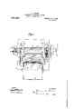
specificatiomand in wh1ch F igure l, is a plan View of the complete machine; Fig. 2, a front elevation of the same; Fig. 3, a section on the line. 3-3 of Fig. 2; Fig. 4, a side view; Fig. 5, a section on the line 55 of Fig. 4; Fig. 6, an elevation of a part of the machine, showingparticularly the automatic trip mechanism for arresting the operation when the desired number of increments of active material has been introduced within the tubes; Fig. 7, a 7,
separate side elevation of one of the tamp ing plungers; Fig. 8, a front view of the same, partly broken'aw'ay; Fig. 9, .a rear view, corresponding to Fig. 8;-Fig. 10, a detached View of the stopping pawl; Fig. 11, a section on the line 1111 of Fig. 6;
Fig. 12, a section on line 12-12 of Fig. 3,
on an enla-r ed scale, illustrating the feeding shaft and eeve; Fig. 13, a side elevation, part1 in section on. the samescale as Fig. 12, oh the feeding shaft; Fig. 14, a section on the line 14-44 of Fig. 12; Fig. 15, a section-on the line 15l5 of Fig. 13 and, F 1g. 16, a section through two of the pockets or tubes, showing the same partly filled with active material. I 1
In all the above views, corresponding parts are nepresented by the-same numerals of reference.
The frame of the machine comprises a base 1, sides 2+2, having'integral support- The tubes or pockets (3 (see Fig. 16) are formed of thin perforated sheet iron or steel, preferably, carefully electro plated with an alloy of nickel and cobalt, and subsequently subjected to a welding temperature in a hydrogen atmosphere, so as to remove anyconditlon of tension in the .electro-deposited 1 filled, as will be obvious.
film, and also to superficially weld the, metal at the seam to strengthen the latter. In practice, these tubes are about 4 inches in length, and one-quarter of an inch in inter nal diameter. A number of these tubes are clamped tightly between holding plates 77 and locked together by aholding bolt 8 at each side, and seated upon a suitable bed-plate 9, carrying studs 10, which fit snugly within the lower ends of thetubes 6, so as to present a clearance space at the bottom of each tube to permit the metal to be compressed, for the purpose of sealing the tubes. At the upper end a similar'clearance space is provided by arresting the feed of material before the tubes become entirely The bed-plate 9 is provided at each side with a pivoted cam 11, (Figs. 4 and which may be operated to separate the bed-plate 9 from the clamping plates 7-7, after the tubes have been filled. The clamping plates and bed-plate having been thus assembled with the number of tubes in position between the clamping plates, are held firmly against a support 12 by means of a screw 13. In this position the holes formed between the clamping 'plates-77 and 'corresponding to the several tubes, will be located immediately below a guide" 14, carried by the arm 3, through which the plungers pass.
Supported by the guide 1a is a hopper 15, having a number of partitions 16 therein, di-
viding the hopper into a plurality of sections corresponding to the number of tubes to, be filled. The hopper is merely an auxiliary device for receiving the succemive increments of active material to be introduced within the pockets or tubes and acts merely as a guide for directing these increments delivered by themain hopper 17 into the several tubes. The main hopper containing the supply of active material is carried by the arms 4.-4=, and its bottom consists of a sleeve 18 having to and bottom openings 19 therein, correspon ing to the several sections of the auxiliary hopper 15. Rotatably mounted in this sleeve 18, is a feeding shaft 20, provided with a corresponding series of poo ets 21 for receivlng the increments of active material at the upper openings 19 and discharging them into the lower openings into the auxiliary hopper, as will be understood. The shaft is driven by a sprocket chain 22 from a countershaft 23, operated by gearing 24: and 25 from a main shaft 26, the
The driving belt 35 normally engages the fastpulley 27. Cotiperating with the belt 35 is a beltshifter 36 carried on the end of a longitudinally movable rod 37 provided with a handle 38 and adapted to be stressed by a spring-39 so as to shiftthe belt to the loose pulley when released. The rod 37 is normally locked inposition to maintain the belt 35 on the fast pulley 27 by means of a finger 40 engaging the horizontal bracket 4.1 secured to one of the sides 2-2 of the machine. This er is also provided ith an inclined surface 42 (Fig. 11) with w V h a tripper 43 is adapted to engage, so as to elevate the finger and release it from the bracket 41 permitting the spring 39 to move the rod 37 and shift the belt to the loose pulley, thereby stopping the machine. The tripper .43 is carried on a shaft 44%, mounted in a bracket 45 and provided with a worm gear 46 with which a worm 47 on the shaft 23 engages. Consequently as the machine operates the tripper will slowly make a complete'rotation and at the completion thereof,- will elevate the finger 40 as explained, to arrest the operation of the machine, the ,parts being so proportioned that this result takes place when exactly the right amount of active material has been introduced within the pockets or tubes. In orderjgo prevent overthrow, resulting in possible irregu-- larity in the number of increments supplied to each pocket or tube, I provide an arresting pawl 48, adapted to be thrown down upon, and engage a pin 49, carried-on the gear 24 when the belt is shifted. The tail of this arresting pawl is normally depressed .so as to keep the pawl out of the path of the pin 49 bya cam 50 on the rod 37. 'Conplungers will be picked up by these teeth successivelyv and the plungers when released will also fall in rapid succession, instead of simultaneously. "This provides for a somewhat'smoother operation in practice and more uniformly distributes the work to be developed and the strains-encountered.
The operation of the machine has already been generally indicated by the precedir description andmay be briefly summariz A suflicient number of empty pockets or tubes is first placed within the clamping plate 7 and lock firmly in position by a screw 13.
Active material is supplied to the hop er 17 and iskept distribut therein as um ormly as ossible. Power bein applied to the sha 26, the shaft 23 be rotated and drives the feed shaft 20, resulting in sucremoved from the main hopper by the several pockets 21' and deposited in the sections of the aum'liary hopper, falling therefrom under the lower ends of the plungers into the several tubes. At the same time, the teeth on the cylinder 34will successively engage the several racks 33 of the plungers,elevating all of the plun 'e'rs until, the last teeth 'on the cylinder 34 eaves the'racks'successively, permitting the plungers to drop in rapid succession into the tubes to tamp the tubes in a tube-filling and tampmg machine, comprising two clamping members, means for reinovably locking the same together, a separate base andcam mechanism for movthe clampin members relatlvely to said base, substantial y as set forth.
Preferably, the mechanism is so. designed that the plungers will be elevated and dropped twice upon each increment, but obviously the feeding mechanism may be so operated, in its relation to the tamping'mechanism that the plungers may be elevated and dropped.
increments introduced therein, as explained.
only once, or if desired, more than twice for each increment. When the proper amount of active material has been thus introduced each tube, the tripper 43 comes be-' neath the finger 40 to release 'the same, thereby shifting the plate on to the loose pulley. At the same time the arresting awl will be "released to fall into. the path 0 the. pin 49,v
so as to prevent the spur gear 24 from making more than a complete rotation before the machine is stopped. The screw 13 is now released, permitting the blocks 7 -7 and base 9 to be removed, after which the cams 11 are operated to separate the blocks 7 from the'bed plate 9, and finally, the tie bolts 8 are released to engage the two blocks and permit the'filled tubes to be removed.
Having now described my invention, what I claim as new therein and desire to secure by Letters Patent is: t
1. In a tube filling and tamping machine,
the combination'with a tube support, means for feeding-successive increments of material to the same, of-a plunger coo'perating therewith for automatically applying a tamping 1 pressure to each increment introduced withof tubes arranged vertically and side by side, of mechamsm for introducing successive Increments of material s multaneously to the several tubes, a series of plungers eor-, :respondingto said tubes, means cooperating with the feeding mechanism for applying 'a tamping pressure to each increment after its introduction within the tubes, means for arresting the feeding and tamping operations, and means for automatlcally operatfing said arrest-ing means at the end of a given number of tamping operations, substantially .aS set forth.
cessive increments of active material being 5 3. In a tube filling and tamping mechanism, the combination 'of a holder for supporting the tub'eagainst disrupting pressure, said holder comprising an elevation ;adapted to enter'the lower end of said tube; "to prevent the filling thereof, mechanism for introducing increments of material successively into said tube, and aplunger adapted :to enter said tube for imposing a tampijiglgg .pressure upon each increment, substantia y as set forth.
4. A support for sustaining a plurality of the combination with mechanism for vertically sustaining the tube and mechanism for feeding successive increments of material thereto, of a gravity plunger movable into and out of the tube, a rack carried by the plunger and a partially toothed drum for elevating the plunger to the same predetermined extent above the level of the material in the tube each time the plunger is so raised, and then releasing the plunger to permit the same to drop and deliver tamping blows to the increments of material, the number of teeth on the rack being considerably greater than'on the drum, whereby the plunger may be caused to fall a uniform distance on the surface ofthe material in the tube each reciprocation of the plunger, regardless of the level of the material in the tube, throughout a wide range of positions of'the plunger, substantially as set forth.
G. In tube-filling and tamping mechanism, comprising the combination with means for sustaining a series oftubesivertically side'by side, and mechanism for feeding successive increments of material to said tubes, of a series of plungers cotiperating with the tubes, a rack on each plunger and a partially toothed drum for engaging the racks of the several plungers for elevating the same to the same predetermined distance above the level of the material within thet-ubes each time the plungers are so raised, and for releasing the plungers whereby the latter will fall and dehver tamping blows to the increments of terial delivered to the .tubes, the number of teet on the racks being considerably eater than the teeth co-acting therewith o the drum, whereby the plungers may' be caused to fall a uniform distance on the surface of the material in the tubes each reciprocation of the plungers, regardless of the level of the material in the tubes,
throughout a wide range of positions of the plungers, substantially as set forth.
7. In tube-filling and tamping mechanism,
. the combination with means for sustaining a series of tubes in a vertical position side by side, and mechanism for feeding increments of material to said tubes, of a series of tamping plungers coiiperating with the tubes, a rack on each plunger and a drum having a series of teeth extending only part, way around the periphery of the drum coiiperatingwith each rack, the corresponding teeth of the different series being disposed in a line inclined somewhat to the longitudinal axis of the drum, the said drum engaging the racks of the several plungers for elevating the same successively to the szim'e predetermined distances above the level of the material within the tubes each time the plungers are so raised, and successively releasing and permitting the pl'ungers to drop by gravity to impart tamping blows to the increments of material delivered to said sleeve and formed with a pocket therein for selecting and delivering to the tube increments of material, substantially as and for the purposes set forth.
9. In tube-filling and tamping mechanism, the combination with means for supporting vertically, side by side, aplurality of tubes, a series of tamping plungers cotiperating with said tubes for delivering. tamping.
blows to the material delivered to thesame, of a hopper containing material to be supplied to saidtube and an apertured sleeveforming the bottom of saidhopper, and a shaft within said sleeveand provided with a series of pockets for selecting increments of material and delivering the same to the several tubes, substantially as set forth.
10. in tube-filling and tamping mechanism, the combination with means for sustaining a plurality of tubes side by side in a Vertical position, a series of tamping plungers co' operating with said tube, mechanism for ele vatlng and releasing said. plungers, and means for arresting the operation of such mechanism when a predetermined number of increments of materialhav'e been introduced within the tubes, substantially as and for the purposes set forth.
11. In tube-filling and tamping mechanism, the combination with means for sustaining a plurality of tubes in a vertical position side by side, means for feeding successive increments of material to said tubes, a series of V plungers 'coiiperating with the tubes for tamping the-increments of material delivered to the same, mechanism for operating said plungers, a drum operated from said mechanism and a tripping device actuated by said drum for arresting said mechanism when the drum has made a predetermined number of rotations, substantially as set forth. 7 I V I V 12. 'In tube-filling and tamping mechanism,
the combination with means for sustaining a plurality of tubes in a vertical position side by side, means for feeding successive increments of material to the said tubes, a series of plungers coiiperating with the tubes for t-amping the increments of material. delivered to the same, mechanism for operating said plungers, a drum 0 erated from said mechanism, a tripping evice actuated by said drum for arresting said mechanism when the drum has made a predetermined ered to the same, mechanism for operating.
said plungers, a drum operated from said mechamsm, a tripping device actuated by sald drum for arresting said mechanism when the drum has made a predetermined number of rotations, a normally elevated arresting pawl, and'means for releasing said arresting pawl when said tripping mechanism operates, substantially as and for the purposes set forth.
14. In a tube filling machine, the combination of a tube support, a feed device for sup plying successiveincrements of material to the tube, means for operating, said feed device, means for arresting said feed device, and means driven by said operating means for operating the arresting means as soon as a given number of increments have been supplied, substantially as set forth.
15. In atube filling machine, the combination of a tube support, a plunger adapted to enter the tube, means for operating said plunger, means for arresting said operating means, and means driven by said operating means for operating the arresting means at the end of a given number of movements of the plunger, substantially as set forth.
16. In a tube filling machine, the combination of a tube support, a feed device for supplying successive increments of material'to the tube, means for driving said feed device, a tripper for disconnecting said driving means, and a lock -operated simultaneously with the tripper to prevent movement due to momentum of the parts disconnected by the tripper, substantially as set forth.
17. In a tube filling machine, the combinatio n'of a tube support, a feed device for supplying successive increments of material to the tube, means for driving said feed device comprising a belt, a fixed and a loose pulley, means for automatically shifting said belt at the end of a predetermined number of revolutions of said fixed pulley, and a lock for said feed mechanism operating simultaneously With said belt shifting device to prevent motion due to momentum, substantially as set forth.
, This specification signed and witnessed this 12th day of October, 1905.
THOS. A. EDISON. Witnesses:
FRANK L. DYER,
MINA C. MAoA-RT UR.
Priority Applications (1)
| Application Number | Priority Date | Filing Date | Title |
|---|---|---|---|
| US28269205A US936433A (en) | 1905-10-14 | 1905-10-14 | Tube filling and tamping machine. |
Applications Claiming Priority (1)
| Application Number | Priority Date | Filing Date | Title |
|---|---|---|---|
| US28269205A US936433A (en) | 1905-10-14 | 1905-10-14 | Tube filling and tamping machine. |
Publications (1)
| Publication Number | Publication Date |
|---|---|
| US936433A true US936433A (en) | 1909-10-12 |
Family
ID=3004855
Family Applications (1)
| Application Number | Title | Priority Date | Filing Date |
|---|---|---|---|
| US28269205A Expired - Lifetime US936433A (en) | 1905-10-14 | 1905-10-14 | Tube filling and tamping machine. |
Country Status (1)
| Country | Link |
|---|---|
| US (1) | US936433A (en) |
Cited By (1)
| Publication number | Priority date | Publication date | Assignee | Title |
|---|---|---|---|---|
| US2873049A (en) * | 1955-05-20 | 1959-02-10 | Schafer Flottmann & Co G M B H | Process and apparatus for distributing a fluidized solid material |
-
1905
- 1905-10-14 US US28269205A patent/US936433A/en not_active Expired - Lifetime
Cited By (1)
| Publication number | Priority date | Publication date | Assignee | Title |
|---|---|---|---|---|
| US2873049A (en) * | 1955-05-20 | 1959-02-10 | Schafer Flottmann & Co G M B H | Process and apparatus for distributing a fluidized solid material |
Similar Documents
| Publication | Publication Date | Title |
|---|---|---|
| JP2001206315A (en) | Method and apparatus for forming cigarette block and delivering it to packaging machine of multiple working passage style | |
| US1208802A (en) | Sugar tablet or cube boxing machine. | |
| US936433A (en) | Tube filling and tamping machine. | |
| GB1433134A (en) | Packaging articles such as apples in a layer or layers | |
| US2029299A (en) | Combined filling and capping machine | |
| US3091067A (en) | Automatic tablet filler | |
| US774378A (en) | Machine for decapping, filling, and recapping capsules. | |
| US2103387A (en) | Article feeding construction | |
| US2366811A (en) | Packaging machine | |
| US1728394A (en) | Method and apparatus for filling bags | |
| US3210833A (en) | Storage battery assembly machines | |
| JPS58193229A (en) | Feeder for packing material | |
| US3614850A (en) | Method for packaging loose fibrous material from a continuous flow | |
| US1258012A (en) | Combined rack-filling and carton-loading machine. | |
| US2935227A (en) | Capsule feeding mechanism for packaging machines | |
| US641546A (en) | Battery-filler. | |
| US2873049A (en) | Process and apparatus for distributing a fluidized solid material | |
| US2133189A (en) | Article counting and stacking mechanism | |
| US1476223A (en) | Method of and apparatus for feeding articles | |
| US1072429A (en) | Filling-machine. | |
| US1163107A (en) | Nail-keg-packing machine. | |
| US812221A (en) | Machine for use in packing biscuits. | |
| US1559009A (en) | Automatic cigar-bunching machine | |
| US208903A (en) | Improvement in machines for gaging cartridges | |
| US1396642A (en) | Dry-cell tamping apparatus |