US936413A - Locomotive-engine. - Google Patents
Locomotive-engine. Download PDFInfo
- Publication number
- US936413A US936413A US50195609A US1909501956A US936413A US 936413 A US936413 A US 936413A US 50195609 A US50195609 A US 50195609A US 1909501956 A US1909501956 A US 1909501956A US 936413 A US936413 A US 936413A
- Authority
- US
- United States
- Prior art keywords
- truck
- spring
- journal
- main
- main frame
- Prior art date
- Legal status (The legal status is an assumption and is not a legal conclusion. Google has not performed a legal analysis and makes no representation as to the accuracy of the status listed.)
- Expired - Lifetime
Links
- 230000003137 locomotive effect Effects 0.000 description 13
- 238000005266 casting Methods 0.000 description 8
- 230000008878 coupling Effects 0.000 description 5
- 238000010168 coupling process Methods 0.000 description 5
- 238000005859 coupling reaction Methods 0.000 description 5
- 230000006872 improvement Effects 0.000 description 5
- 230000013707 sensory perception of sound Effects 0.000 description 5
- 230000007246 mechanism Effects 0.000 description 4
- 238000010276 construction Methods 0.000 description 3
- 230000009467 reduction Effects 0.000 description 2
- 230000000717 retained effect Effects 0.000 description 2
- 240000001546 Byrsonima crassifolia Species 0.000 description 1
- 235000003197 Byrsonima crassifolia Nutrition 0.000 description 1
- 240000002769 Morchella esculenta Species 0.000 description 1
- 235000002779 Morchella esculenta Nutrition 0.000 description 1
- 241001274197 Scatophagus argus Species 0.000 description 1
- MTCFGRXMJLQNBG-UHFFFAOYSA-N Serine Natural products OCC(N)C(O)=O MTCFGRXMJLQNBG-UHFFFAOYSA-N 0.000 description 1
- 230000009471 action Effects 0.000 description 1
- 235000015115 caffè latte Nutrition 0.000 description 1
- 238000006073 displacement reaction Methods 0.000 description 1
- 238000010438 heat treatment Methods 0.000 description 1
- 239000000463 material Substances 0.000 description 1
- 239000006187 pill Substances 0.000 description 1
- 230000000153 supplemental effect Effects 0.000 description 1
Images


Classifications
-
- B—PERFORMING OPERATIONS; TRANSPORTING
- B61—RAILWAYS
- B61F—RAIL VEHICLE SUSPENSIONS, e.g. UNDERFRAMES, BOGIES OR ARRANGEMENTS OF WHEEL AXLES; RAIL VEHICLES FOR USE ON TRACKS OF DIFFERENT WIDTH; PREVENTING DERAILING OF RAIL VEHICLES; WHEEL GUARDS, OBSTRUCTION REMOVERS OR THE LIKE FOR RAIL VEHICLES
- B61F5/00—Constructional details of bogies; Connections between bogies and vehicle underframes; Arrangements or devices for adjusting or allowing self-adjustment of wheel axles or bogies when rounding curves
- B61F5/26—Mounting or securing axle-boxes in vehicle or bogie underframes
- B61F5/30—Axle-boxes mounted for movement under spring control in vehicle or bogie underframes
- B61F5/36—Arrangements for equalising or adjusting the load on wheels or springs, e.g. yokes
Definitions
- FRANCIS J' COLE AND FRANK F. SCOVILLE, QF SCHENECTADY, NEW YORK.
- Our present invention is an improvement upon that for which Let-ters Patent of the as assignee of Francis J. Cole, under date of November l, 1904:.
- the object of our invention is to provide means whereby all the advantages of the improvement of said Letters Patent shall be retained, and the further advantages of a nance of the normal relation of the springs to the main and truck frames, shall he afforded.
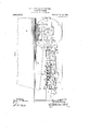
- lfigure l is a side View, in elevation, of the rear portion of a locomotive engine, illustrating an application of our invention
- Fig. 2 a rear view, partly in section, of the saine
- Fig. 3 a side view, on an enlarged scale, of a trail* ing truck spring and its floating yoke, with the middle portion of the latter in section
- Fig. 4 a plan or top view of the floating yoke
- Fig. 5 a plan view of the truck, detached
- Fig. 6, a side view of the same
- Our invention is, as in Letters Patent No. 778,713 aforesaid, herein illustrated as applied in a locomotive engine having a pluralit'y o f pairsjof driving wheels, l, only the rear pair of which is shown, 'and having its boiler, 4, provided with a Wide tirebox, 5, which 1s overhung-or set behind the rear Specification of Letters Patent. aplacar-ion ined June 14, 1909.
- the driving wheels are fixed upon axles, ld, the journals of which rotate in boxes, le, litted in pedestals in the main frame members, 8, and the overhanging weight of the firebox is carried upon a radial truck, the construction of which will now be described.
- rl ⁇ he frame of the truck which is of the two wheeled radial type, is substantially triangular in plan, and is made up of two forwardly and inwardly inclined radius arms, G5, a front connecting plate, (3V), which is .secured to, and connects together, the forward ends of the arms, (35, and is provided with a center pin socket, (37,' a U shaped rear member, ⁇ 68, ⁇ and two journal box castings, (59, which form parts of the sides of the truck frame, said' castings having lateral arms, 70, which are connected to the radius arms, (l5, and to the rear member, (38, re-I spectively.
- the portions of the main engine frame members, 8, in which the journal boxes, l, of the axles, l," of the driving wheels are fitted, are of the usual bar type, and the portions, Sg, of said main frame members which extend rearwardly from the pedestals of-the rear driving axle and below the firebox, are made separate from the forward portions, and are deeper and narrower than the latter, to which they are secured remov ably by transverse bolts adjacent to the rear pedestals.
- the rear sections, S5, of the main frame members are connected and braced transversely by a suitable cross tie, 7l, which is preferably in the forni of thc expansion cross tic set forth in latent No.
- the lateral movements of the truck are controlled and limited, and the trucknormally maintained with its longitudinal ecutral plane in coincidence with that of the locomotive, by a transverse centering spring,
- the centering mechanism is substantially similar m construction and manner of operation to that set forth in latent No. 773,713, and does not, in and of itself, form part. of our present invention.
- the truck axle, 3, extends outwardly beyond its wheel seats suliiciently far to provide outside journals, which rotate in journal bearings, 69a, litted in thel journal box castings, G9, in the usual n'ianner.
- the rear main frame members, 8H are supported upon the truck axle through the intermediation of springs, 12, ythe bands, 42, of which are seated upon the tops of the journal box castings, GS), as presently to be described. r'lhe rear ends of the truck springs are connected by spring hangers, 42", tothe rear main frame sections, 8g, and their yforward ends are connected by spring hangers, 4f.
- equalizcrs 43, pivoted in supports, 44, depending from the main frame members, 8g.
- the forward ends of the equalizers are connected to the rear spring hangers, 1-1e,-of the springs, Ll1, of the driving",
- Thetruek spring bands, ft2 are supported on the tops of the journal box castings, (it), by means, which will now be described, whereby lateral movement of the latte and other counected members of the truck frame is permitted in passing curves, without displacement of the spring bands and springs; the action of the centering mechanism in there- 'after returning thc truck to normal central position is aided and supplemented; and the truck springs are guided and controlled so as to be prevented from moving otherwise than vertically, and caused to adjust themselves to the alincment of the journal boxes in any required position, either longitudinal or vertical, without liability to cocking" of the spring seats.
- the spring bands, 112 are I'ittcd in spring seats, which rest, either directly 0r through the intermediation of friction plates, as hereinafter described ⁇ on the journal box castings, (S9, each of said spring,r seats comprising an upper socket section, 42d, which is provided with a recess in itsl top to receive the spring band, and is bored out centrally to tit, and be movable about, a cylindrical projection or pivot, 42', on the top of a lower body section, 42K Each of the.
- truunion blocks, 51 are coupled to the spring sea t body sections, 42", byv transverse pins, 51", the projecting ⁇ ends of which lit in sockets in the body sections and form trunnions at right angles to the trunnions, 51a.
- the entire resistance 'for centeringthe truck may, however, be provided as a frictioual one, and the independent spring centering mechanism be dispensed with, if desired, by the interposition of inclined plane friction plates, 81, between the spring seats and the journal boxes.
- the friction plates, 81 are provided With central cylindrical projections or bosses, 81a, on their lower sides, which fit in corresponding sockets in the tops of the journal boxes, and with transverse tenons, 81h, on their upper sides, which lit in corresponding mortises iu the bottoms of the spring scat body sections.
- the truck herein set forth embodies the advantages, among others, of enabling the supplemental outside rear frame bars of Patent No. 7 73,713, and the interposed castings through which they arel connected to .the main .trame bars to be dis ensed with thereby eliecting a material reduction in wit-ight.
Landscapes
- Engineering & Computer Science (AREA)
- Mechanical Engineering (AREA)
- Vehicle Body Suspensions (AREA)
Description
Patented 0st. 12, 1909. 4 SHEETS Smm V1.
o www WNW/lfm? E. J. COLE & E. E. SCOVILLE.
LOCOMTIVE ENGINE.
P. I. COLE @L F. I. SGOVILLE.
' LCOMOTIVE ENGINE.
APPLIUATION FILED JUN13'14,1909.
Patented Got. 12, 1909.
4 SHEETS-SHEET 2.
WHT?! 555 ES 67M mmm-armas MLM-M F. J. com @L 1w. scovlLLE.
LOGOMOTIVE ENGINE.
l APPLICATION FILED JUNE 14,1909. 936,41 Patented oet. 12, 1909.
4 SHEETS-SHEET' 3.
F. J. COLE n F. P. SOVILL.
LOOMOTIVE ENGINE.
APPLIOATloN HLM) JUNE 14,1909.
936,41 3., mente@ oct. 12, 1909.
4 SHEETS-SHEET 4.
WHTNESSES Umted States No. 773,7l3 were granted and issued to American Locomotive Company,
lATENT OFFCE.
FRANCIS J'. COLE AND FRANK F. SCOVILLE, QF SCHENECTADY, NEW YORK.
LOCOMOTIVE-ENGINE.
To all whom it may concern:
Beit known that we, FRANCIS J. Conn and FRANK F. Scovnmn, both of Schenectady, in the county of Schenectady and State of New York, have jointly invented a certa-in new and useful Improvement in Locomotive- Engines, of which improvement the following is a specification.
Our present invention is an improvement upon that for which Let-ters Patent of the as assignee of Francis J. Cole, under date of November l, 1904:.
The object of our invention is to provide means whereby all the advantages of the improvement of said Letters Patent shall be retained, and the further advantages of a nance of the normal relation of the springs to the main and truck frames, shall he afforded.
The improvement claimed is hereinafter fully set forth.
.In the accompanyingdrawings: lfigure l is a side View, in elevation, of the rear portion of a locomotive engine, illustrating an application of our invention; Fig. 2, a rear view, partly in section, of the saine; Fig. 3, a side view, on an enlarged scale, of a trail* ing truck spring and its floating yoke, with the middle portion of the latter in section; Fig. 4, a plan or top view of the floating yoke; Fig. 5, a plan view of the truck, detached; Fig. 6, a side view of the same; Fig. 7, a transverse section, on an enlarged scale, through one of t-he ioating yoke bearings, taken on the line a a of Fig. S; Fig. 8, a longitudinal central section through a pair of said bearings; Fig. 9, a plan or top view of a journal box; Fig. l0, a transverse section through a spring seat friction plate, on the line of Fig. 9; Fig. l1, a side view, in elevation, of the same; and Fig. 12, a vertical longitudinal central section through ay journal box,with a super-posed friction plate and spring seat in elevation.
Our invention is, as in Letters Patent No. 778,713 aforesaid, herein illustrated as applied in a locomotive engine having a pluralit'y o f pairsjof driving wheels, l, only the rear pair of which is shown, 'and having its boiler, 4, provided with a Wide tirebox, 5, which 1s overhung-or set behind the rear Specification of Letters Patent. aplacar-ion ined June 14, 1909.
Patented ont. 12, 1909. serial No. 50i,956.
driving wheels. The driving wheels are fixed upon axles, ld, the journals of which rotate in boxes, le, litted in pedestals in the main frame members, 8, and the overhanging weight of the lirebox is carried upon a radial truck, the construction of which will now be described.
rl`he frame of the truck, which is of the two wheeled radial type, is substantially triangular in plan, and is made up of two forwardly and inwardly inclined radius arms, G5, a front connecting plate, (3V), which is .secured to, and connects together, the forward ends of the arms, (35, and is provided with a center pin socket, (37,' a U shaped rear member, `68,\and two journal box castings, (59, which form parts of the sides of the truck frame, said' castings having lateral arms, 70, which are connected to the radius arms, (l5, and to the rear member, (38, re-I spectively.
The portions of the main engine frame members, 8, in which the journal boxes, l, of the axles, l," of the driving wheels are fitted, are of the usual bar type, and the portions, Sg, of said main frame members which extend rearwardly from the pedestals of-the rear driving axle and below the firebox, are made separate from the forward portions, and are deeper and narrower than the latter, to which they are secured remov ably by transverse bolts adjacent to the rear pedestals. The rear sections, S5, of the main frame members are connected and braced transversely by a suitable cross tie, 7l, which is preferably in the forni of thc expansion cross tic set forth in latent No. 773,713, and which is provided with bearingwr sockets, through which and through thc/socket, (37, of the truck frame connecting plate, (3G, the center pin, 72, of the truck passes, and is held in position by a. key, 72, the truck swiveling upon the axial line of the pill, 72.
The lateral movements of the truck are controlled and limited, and the trucknormally maintained with its longitudinal ecutral plane in coincidence with that of the locomotive, by a transverse centering spring,
j 7 5, which is fitted in a box or case, 7 G, se-
cured by flanges, 7G, to a transverse casting connecting the rear members, 8g, of the mainframe, and abuts through followers, 77, and
thrust rods, 78, on socket lugs, 79, xed to the rear members, 68, of the truck frame.4
The centering mechanism is substantially similar m construction and manner of operation to that set forth in latent No. 773,713, and does not, in and of itself, form part. of our present invention.
The truck axle, 3, extends outwardly beyond its wheel seats suliiciently far to provide outside journals, which rotate in journal bearings, 69a, litted in thel journal box castings, G9, in the usual n'ianner. The rear main frame members, 8H, are supported upon the truck axle through the intermediation of springs, 12, ythe bands, 42, of which are seated upon the tops of the journal box castings, GS), as presently to be described. r'lhe rear ends of the truck springs are connected by spring hangers, 42", tothe rear main frame sections, 8g, and their yforward ends are connected by spring hangers, 4f. to the rear ends of equalizcrs, 43, pivoted in supports, 44, depending from the main frame members, 8g. The forward ends of the equalizers are connected to the rear spring hangers, 1-1e,-of the springs, Ll1, of the driving",
axle, v1d, nearest the iirebox. Thetruek spring bands, ft2, are supported on the tops of the journal box castings, (it), by means, which will now be described, whereby lateral movement of the latte and other counected members of the truck frame is permitted in passing curves, without displacement of the spring bands and springs; the action of the centering mechanism in there- 'after returning thc truck to normal central position is aided and supplemented; and the truck springs are guided and controlled so as to be prevented from moving otherwise than vertically, and caused to adjust themselves to the alincment of the journal boxes in any required position, either longitudinal or vertical, without liability to cocking" of the spring seats.
To these ends, the spring bands, 112, are I'ittcd in spring seats, which rest, either directly 0r through the intermediation of friction plates, as hereinafter described` on the journal box castings, (S9, each of said spring,r seats comprising an upper socket section, 42d, which is provided with a recess in itsl top to receive the spring band, and is bored out centrally to tit, and be movable about, a cylindrical projection or pivot, 42', on the top of a lower body section, 42K Each of the. spring seats, 42d, Lllf, fils freely in a central opening formed in a ioating yoke, 5t), the ends of which are curved inwardly iu front and rear of the adjacent truck wheel, and are coupled, by' longitudinally extending pivots, to lugs, 50", on the rear main frame members, 8g. A truunion block, 51, having trunnions or pivots, 5l, on its ends, passes freely through a longitudinal opening in cach of the spring seat body sections, 42, the trunnious, 51, filling in sockets in transverse bearingblocks, 50, secuied to the adjacent floating yoke by bolts, 50d. The
if, truunion blocks, 51, are coupled to the spring sea t body sections, 42", byv transverse pins, 51", the projecting` ends of which lit in sockets in the body sections and form trunnions at right angles to the trunnions, 51a.
l t will be seen thatby the construction above described, complete freedom for angular movement of the yokes is permitted, and that, in both lateral movements of the journal boxes relatively to themain frame, and vertical movements of the main frame relatively to the journal boxes and truck` frame, the springs are retained in their normal relation to the main and the truck frame, and are also always maintained in proper alinementV \vtt`h,`and truc bearing on, the journal boxes, by rheans of the right angled trunniouconnectioils of their seats with the floating vokes.
'libe friction ofthe Spring Seat body Sec* l tions on the tops of the journal boxes acts,
iu conjunction with the centering mechanism. hcreinbefore described, to resist the transverse motion of the truck. The entire resistance 'for centeringthe truck may, however, be provided as a frictioual one, and the independent spring centering mechanism be dispensed with, if desired, by the interposition of inclined plane friction plates, 81, between the spring seats and the journal boxes. As shown in Figs. 9 to 12 inclusive, the friction plates, 81, are provided With central cylindrical projections or bosses, 81a, on their lower sides, which fit in corresponding sockets in the tops of the journal boxes, and with transverse tenons, 81h, on their upper sides, which lit in corresponding mortises iu the bottoms of the spring scat body sections. 492K The friction plates are adjusted so that the tenons stand at an angle to the truck axle, as shown in Fig. 9, and the top surfaces of the friction plates on opposite sides of the tenons, are inclined planes. 'l`he abutting surfaces of the oorresponding portions of the spring seat body sections are correspondingly inclined, as shown iu Fig. 1'2. lt will therefore be seen that lateral movement of the truck frame, in either direction, is resisted by the friction between the abutting inclined plane surfaces of the spring seat body sections and friction plates.
The truck herein set forth embodies the advantages, among others, of enabling the supplemental outside rear frame bars of Patent No. 7 73,713, and the interposed castings through which they arel connected to .the main .trame bars to be dis ensed with thereby eliecting a material reduction in wit-ight. The ad vantage of the floating yokes and connpetions over the spring guides of said patent, in the more perfect adjustability of the springs to the alinement of the journal boxes, and in the reduction of necesu. in
sary distance between the transverse centers of truck journals, `will be apparent.
Our present invention, while. morel par secure by Letters Patent:
l. In a locomotive engine, the combination of a main frame, driving wheels `iournaled in bearings therein, a radial truck pivoted to 'the main frame, springs through which weight borne. by the main frame is transmitted to the journal hoxes'of the truck, and floating Connections through which said springs are pivoted, in substantially horizontal planes, 'to the main frame.
2. ln a locomotive engine, the combination of main frame, driving wheels journaled y in hearings therein, a radial trunk pivoted to the main freine, springs through which weight borne by the main frame is crane mitted to the journal hores of the truck, seats in which said Springs are supported on the journal boxes, and. iioating connections coupling said spring to the main frame in suhstantiall7 horizontal planes.
S5 ln a locomotive engine, the combination of main frame, driving Wheels ,iournaled in bearings therein, a radial truolr pivoted to the main frame, springs t .rough which weight borne 'by the mein frame is transi'o init-ted to the journal. boxes of the truck, Seats in lwhich said 'springs are .Supported on the `journal hoxes,'a1id pivotal connections, comprising pairs of trunnione set'at right anglee, coupling said spring seats to the main frame.
el. ln a` locomotive engine, the combination ot a main frame, driving wheels journaled in bezirings therein, radial truelr pivoted to the main frame, Springs through which weight borne by the main 'frame is transmitted to the journal hores of the truelr,
seats in which Said springs are supported on the journal boxes, and VFloating yolres, pivoted at their ends to ihe mein frame and Coupled centrally vto the spring seats.
5. 'lna loeomotive engine, the combination of a. main freine, driving` Wheels journaled in heorings therein., a radial truel; pivoted to the main traine, sjrings through 'which SD `weight borne by the main 'frame is.trans knitted to the journal heizen of the truck,
on the Journal ooxee, ne yenes, pivoteo at their ende to the main frame, and pivotal vseats in Whioh'saio Serine@ are supported fie eonneetions, eomprieine; or" trunnione Set at right angles, Coupling said iioating,`
vohee to the Spring (3. ln a locomotive engine, the eomhination of main frame, drivingl Wheely journaled in hearings therein, a radial tru/lr pivoted vo to the main frame, springs through which weight borne hy the main trame is tranemiited to the journal ho of the truck, eeats in ivhieh said spring are supported on the journal uoxee, floating voices, pivoted at their ende to the main ame and sur rounding the spring seats at their (ferriere, triuinion bloeien fit-ting 'freely in the Spriiig seats, transverse trunnione eoupling the trunnion bloelze to the Spring Seats, and longitudinal -trunnions` eounling the trunuion blocks to 'the Heating yokee.
7.y ln n locomotive engine, a floating yoke of U forni having' sockets in its: ends 'tor the reception of .main 'frame Coupling pins and S an opening in its middle portion for the reception o'iI a truck Spring seat.
S. lu a locomotive engine, the Combination of a truck sprino' neet havingglongitudinal through passage, a trunnion block Jo fitting freely in Said paseage and having` trunnions on its ende, transverse trunnio lived to said loloek and iitting in seekers in the spring seat, a iioating yoke ,su rounf the spring seat and hearing hl( s secured o5 to'eaid Floating* yoke ind having seekete receiving the end trunnions oit ,he trnnnion hloeli'.
9. In e locomotive en'ine, the combination of a main frameLdrivn Wheels "iournaled 100 in hearings theiiin a iarial trueh Divoted to theI main anoe., springe througfh i 'eli Weight `borne .by the main traine tranemitted to the journal boxes o the truck, seats in which said sgringe are supported, with the Capacity of relative iiio-.fen'ieiit, on the journal boxes, pivotal eoni'ieotions Coupling said spring seats to the main trame, and means for inwoning an increased difgree oli t'rietional resistance between il Vspring seats and the journal box lt). in' a locomotive eiwine tion ot a main iframe, d naled in hearings there pivo'ted Vto the main framr, springe which weight horno hy 'the main ie is transmitted to the journal boxes of the truelc, seats in which said. Springs are supported, with the eapaeilv of relative mov'nieut, on
the eofihinin lthe journal bonne, pivotal conneeiiionel con;` i2
lll'itnesses S. V@ Tynnn,
(hun il. .ioonne
Priority Applications (1)
| Application Number | Priority Date | Filing Date | Title |
|---|---|---|---|
| US50195609A US936413A (en) | 1909-06-14 | 1909-06-14 | Locomotive-engine. |
Applications Claiming Priority (1)
| Application Number | Priority Date | Filing Date | Title |
|---|---|---|---|
| US50195609A US936413A (en) | 1909-06-14 | 1909-06-14 | Locomotive-engine. |
Publications (1)
| Publication Number | Publication Date |
|---|---|
| US936413A true US936413A (en) | 1909-10-12 |
Family
ID=3004835
Family Applications (1)
| Application Number | Title | Priority Date | Filing Date |
|---|---|---|---|
| US50195609A Expired - Lifetime US936413A (en) | 1909-06-14 | 1909-06-14 | Locomotive-engine. |
Country Status (1)
| Country | Link |
|---|---|
| US (1) | US936413A (en) |
-
1909
- 1909-06-14 US US50195609A patent/US936413A/en not_active Expired - Lifetime
Similar Documents
| Publication | Publication Date | Title |
|---|---|---|
| US1408167A (en) | Car truck | |
| US852444A (en) | Locomotive. | |
| US444181A (en) | Radial car-truck | |
| US773713A (en) | Locomotive-engine. | |
| US1275612A (en) | Locomotive-engine. | |
| US32991A (en) | Improvement in locomotives and steam-carriages for common roads | |
| US435918A (en) | Truck for cars | |
| US999192A (en) | Compensating truck for railway-cars. | |
| US696283A (en) | Locomotive. | |
| US1025522A (en) | Draw-bar mechanism. | |
| US1668340A (en) | Locomotive booster device | |
| US893041A (en) | Locomotive. | |
| US699517A (en) | Locomotive with driven bogie. | |
| US978186A (en) | Articulated locomotive. | |
| US1084388A (en) | Locomotive. | |
| US694787A (en) | Radial car-truck. | |
| US940494A (en) | Forward truck for locomotives. | |
| US133859A (en) | Improvement in locomotive-engines | |
| US2048280A (en) | Underframe for carriages | |
| US485344A (en) | foeney | |
| US1354112A (en) | Axle-box for adjustable locomotive-axles | |
| US53009A (en) | Improvement in bearings of locomotive-axles | |
| US1081372A (en) | Vehicle. | |
| US1143943A (en) | Locomotive trailing truck. | |
| US1101227A (en) | Locomotive trailing-truck. |