US9362039B2 - Composition and method of application to reduce magnetostriction losses in encapsulated microelectronic components - Google Patents
Composition and method of application to reduce magnetostriction losses in encapsulated microelectronic components Download PDFInfo
- Publication number
- US9362039B2 US9362039B2 US13/859,827 US201313859827A US9362039B2 US 9362039 B2 US9362039 B2 US 9362039B2 US 201313859827 A US201313859827 A US 201313859827A US 9362039 B2 US9362039 B2 US 9362039B2
- Authority
- US
- United States
- Prior art keywords
- composition
- coating
- component
- magnetic
- magnetostriction
- Prior art date
- Legal status (The legal status is an assumption and is not a legal conclusion. Google has not performed a legal analysis and makes no representation as to the accuracy of the status listed.)
- Active, expires
Links
- 238000004377 microelectronic Methods 0.000 title claims abstract description 34
- 239000000203 mixture Substances 0.000 title abstract description 43
- 238000000034 method Methods 0.000 title description 5
- 239000000463 material Substances 0.000 claims abstract description 60
- 239000004005 microsphere Substances 0.000 claims abstract description 22
- 229920001296 polysiloxane Polymers 0.000 claims abstract description 9
- 125000000118 dimethyl group Chemical group [H]C([H])([H])* 0.000 claims abstract description 8
- 229920005596 polymer binder Polymers 0.000 claims abstract description 8
- 239000002491 polymer binding agent Substances 0.000 claims abstract description 8
- 229920000642 polymer Polymers 0.000 claims abstract description 7
- 239000011230 binding agent Substances 0.000 claims description 8
- NNPPMTNAJDCUHE-UHFFFAOYSA-N isobutane Chemical compound CC(C)C NNPPMTNAJDCUHE-UHFFFAOYSA-N 0.000 claims description 6
- 239000001282 iso-butane Substances 0.000 claims description 3
- 229920006243 acrylic copolymer Polymers 0.000 claims 1
- 230000005291 magnetic effect Effects 0.000 abstract description 46
- 239000011248 coating agent Substances 0.000 abstract description 36
- 238000000576 coating method Methods 0.000 abstract description 36
- 238000005538 encapsulation Methods 0.000 abstract description 13
- 230000004907 flux Effects 0.000 abstract description 10
- 238000006116 polymerization reaction Methods 0.000 abstract description 6
- 230000005381 magnetic domain Effects 0.000 description 13
- 230000000694 effects Effects 0.000 description 11
- 239000003302 ferromagnetic material Substances 0.000 description 11
- 230000003139 buffering effect Effects 0.000 description 10
- YXFVVABEGXRONW-UHFFFAOYSA-N Toluene Chemical compound CC1=CC=CC=C1 YXFVVABEGXRONW-UHFFFAOYSA-N 0.000 description 6
- 230000008859 change Effects 0.000 description 6
- 229910000859 α-Fe Inorganic materials 0.000 description 5
- 230000000712 assembly Effects 0.000 description 4
- 238000000429 assembly Methods 0.000 description 4
- 150000002118 epoxides Chemical class 0.000 description 4
- 239000000853 adhesive Substances 0.000 description 3
- 230000001070 adhesive effect Effects 0.000 description 3
- 239000008393 encapsulating agent Substances 0.000 description 3
- 230000005294 ferromagnetic effect Effects 0.000 description 3
- 239000006260 foam Substances 0.000 description 3
- 239000002904 solvent Substances 0.000 description 3
- 239000004593 Epoxy Substances 0.000 description 2
- PXHVJJICTQNCMI-UHFFFAOYSA-N Nickel Chemical compound [Ni] PXHVJJICTQNCMI-UHFFFAOYSA-N 0.000 description 2
- 239000005062 Polybutadiene Substances 0.000 description 2
- 229910045601 alloy Inorganic materials 0.000 description 2
- 239000000956 alloy Substances 0.000 description 2
- 230000003466 anti-cipated effect Effects 0.000 description 2
- 230000008901 benefit Effects 0.000 description 2
- 238000010586 diagram Methods 0.000 description 2
- 239000003085 diluting agent Substances 0.000 description 2
- 238000005553 drilling Methods 0.000 description 2
- 229920001971 elastomer Polymers 0.000 description 2
- -1 etc) Polymers 0.000 description 2
- 238000011068 loading method Methods 0.000 description 2
- 230000005415 magnetization Effects 0.000 description 2
- 238000005065 mining Methods 0.000 description 2
- 229920001084 poly(chloroprene) Polymers 0.000 description 2
- 229920002857 polybutadiene Polymers 0.000 description 2
- 229920001195 polyisoprene Polymers 0.000 description 2
- 229920001021 polysulfide Polymers 0.000 description 2
- 239000005077 polysulfide Substances 0.000 description 2
- 150000008117 polysulfides Polymers 0.000 description 2
- 238000002360 preparation method Methods 0.000 description 2
- 230000009467 reduction Effects 0.000 description 2
- 239000005060 rubber Substances 0.000 description 2
- 150000003673 urethanes Chemical class 0.000 description 2
- OEPOKWHJYJXUGD-UHFFFAOYSA-N 2-(3-phenylmethoxyphenyl)-1,3-thiazole-4-carbaldehyde Chemical compound O=CC1=CSC(C=2C=C(OCC=3C=CC=CC=3)C=CC=2)=N1 OEPOKWHJYJXUGD-UHFFFAOYSA-N 0.000 description 1
- NLHHRLWOUZZQLW-UHFFFAOYSA-N Acrylonitrile Chemical compound C=CC#N NLHHRLWOUZZQLW-UHFFFAOYSA-N 0.000 description 1
- RYGMFSIKBFXOCR-UHFFFAOYSA-N Copper Chemical compound [Cu] RYGMFSIKBFXOCR-UHFFFAOYSA-N 0.000 description 1
- 229910052692 Dysprosium Inorganic materials 0.000 description 1
- XEEYBQQBJWHFJM-UHFFFAOYSA-N Iron Chemical compound [Fe] XEEYBQQBJWHFJM-UHFFFAOYSA-N 0.000 description 1
- 229920006169 Perfluoroelastomer Polymers 0.000 description 1
- 239000004698 Polyethylene Substances 0.000 description 1
- 229910052771 Terbium Inorganic materials 0.000 description 1
- 229910001329 Terfenol-D Inorganic materials 0.000 description 1
- 230000002411 adverse Effects 0.000 description 1
- 238000013019 agitation Methods 0.000 description 1
- 238000005275 alloying Methods 0.000 description 1
- 230000009286 beneficial effect Effects 0.000 description 1
- 230000015572 biosynthetic process Effects 0.000 description 1
- 230000008602 contraction Effects 0.000 description 1
- 229910052802 copper Inorganic materials 0.000 description 1
- 239000010949 copper Substances 0.000 description 1
- 230000008878 coupling Effects 0.000 description 1
- 238000010168 coupling process Methods 0.000 description 1
- 238000005859 coupling reaction Methods 0.000 description 1
- 230000001419 dependent effect Effects 0.000 description 1
- 239000006185 dispersion Substances 0.000 description 1
- 238000006073 displacement reaction Methods 0.000 description 1
- KBQHZAAAGSGFKK-UHFFFAOYSA-N dysprosium atom Chemical compound [Dy] KBQHZAAAGSGFKK-UHFFFAOYSA-N 0.000 description 1
- 238000011049 filling Methods 0.000 description 1
- 230000001939 inductive effect Effects 0.000 description 1
- 238000004519 manufacturing process Methods 0.000 description 1
- 238000003913 materials processing Methods 0.000 description 1
- 238000010907 mechanical stirring Methods 0.000 description 1
- 238000002156 mixing Methods 0.000 description 1
- 238000012986 modification Methods 0.000 description 1
- 230000004048 modification Effects 0.000 description 1
- 229910052759 nickel Inorganic materials 0.000 description 1
- 239000002245 particle Substances 0.000 description 1
- 229920000573 polyethylene Polymers 0.000 description 1
- 239000011253 protective coating Substances 0.000 description 1
- 229910052761 rare earth metal Inorganic materials 0.000 description 1
- 238000000926 separation method Methods 0.000 description 1
- 239000007787 solid Substances 0.000 description 1
- 238000006467 substitution reaction Methods 0.000 description 1
- GZCRRIHWUXGPOV-UHFFFAOYSA-N terbium atom Chemical compound [Tb] GZCRRIHWUXGPOV-UHFFFAOYSA-N 0.000 description 1
- 239000003981 vehicle Substances 0.000 description 1
- 125000000391 vinyl group Chemical group [H]C([*])=C([H])[H] 0.000 description 1
- 229920002554 vinyl polymer Polymers 0.000 description 1
Images


Classifications
-
- H—ELECTRICITY
- H01—ELECTRIC ELEMENTS
- H01F—MAGNETS; INDUCTANCES; TRANSFORMERS; SELECTION OF MATERIALS FOR THEIR MAGNETIC PROPERTIES
- H01F27/00—Details of transformers or inductances, in general
- H01F27/02—Casings
- H01F27/022—Encapsulation
-
- H—ELECTRICITY
- H01—ELECTRIC ELEMENTS
- H01F—MAGNETS; INDUCTANCES; TRANSFORMERS; SELECTION OF MATERIALS FOR THEIR MAGNETIC PROPERTIES
- H01F27/00—Details of transformers or inductances, in general
- H01F27/33—Arrangements for noise damping
-
- H—ELECTRICITY
- H01—ELECTRIC ELEMENTS
- H01F—MAGNETS; INDUCTANCES; TRANSFORMERS; SELECTION OF MATERIALS FOR THEIR MAGNETIC PROPERTIES
- H01F27/00—Details of transformers or inductances, in general
- H01F27/34—Special means for preventing or reducing unwanted electric or magnetic effects, e.g. no-load losses, reactive currents, harmonics, oscillations, leakage fields
-
- H—ELECTRICITY
- H01—ELECTRIC ELEMENTS
- H01F—MAGNETS; INDUCTANCES; TRANSFORMERS; SELECTION OF MATERIALS FOR THEIR MAGNETIC PROPERTIES
- H01F41/00—Apparatus or processes specially adapted for manufacturing or assembling magnets, inductances or transformers; Apparatus or processes specially adapted for manufacturing materials characterised by their magnetic properties
- H01F41/005—Impregnating or encapsulating
-
- Y—GENERAL TAGGING OF NEW TECHNOLOGICAL DEVELOPMENTS; GENERAL TAGGING OF CROSS-SECTIONAL TECHNOLOGIES SPANNING OVER SEVERAL SECTIONS OF THE IPC; TECHNICAL SUBJECTS COVERED BY FORMER USPC CROSS-REFERENCE ART COLLECTIONS [XRACs] AND DIGESTS
- Y10—TECHNICAL SUBJECTS COVERED BY FORMER USPC
- Y10T—TECHNICAL SUBJECTS COVERED BY FORMER US CLASSIFICATION
- Y10T428/00—Stock material or miscellaneous articles
- Y10T428/29—Coated or structually defined flake, particle, cell, strand, strand portion, rod, filament, macroscopic fiber or mass thereof
- Y10T428/2982—Particulate matter [e.g., sphere, flake, etc.]
- Y10T428/2984—Microcapsule with fluid core [includes liposome]
Definitions
- the present invention relates to improvements in materials usable for reducing adverse effects upon magnetostrictive materials, and more particularly to a coating that may be used to protect a microelectronic component that must be encapsulated or be rigidly supported, to thereby increase its efficiency.
- the phenomenon of magnetostriction pertains to the change exhibited in a material's dimensions or shape when it is exposed to an external magnetic field. Another perspective on such behavior is that these magnetostrictive materials convert magnetic energy into mechanical energy, as exposure to the magnetic field induces deformation of the material, which is known as the Joule Effect, and which may be measured using a strain gauge to determine the relative displacement of particles in the object (i.e., the ratio of elongation with respect to the original dimension).
- a magnetostrictive material is induced by the Joule effect to elongate in a lengthwise direction, through rotation and reorientation of small magnetic domains therein—regions of uniform magnetic polarization—a corresponding decrease in the material dimension is experienced in the transverse direction, resulting in negligible changes to its volume.
- Increases to the strength of the magnetic field applied to the material further increase the induced strain ( ⁇ L/L-units of micro-length per unit length), until its saturation value ( ⁇ ) is reached, at which generally all the magnetic domains of the material are aligned with the applied magnetic field.
- Terfenol-D a combination of terbium (Ter), iron (Fe), and the rare earth element dysprosium (D).
- Terfenol was developed by the Naval Ordnance Laboratory (NOL), and exhibits roughly 2000 microstrains in a magnetic field of 2 kOe (160 kA/m), so it is the most commonly used magnetostrictive material in engineering applications.
- a common side effect is the annoying humming sound resulting from the 60 Hz applied magnetic field on an AC electrical transformer, where a maximum change in length occurs twice per cycle, producing a 120 Hz humming sound plus harmonics.
- a similar humming may be heard around high power electric lines carrying alternating current.
- magnetic devices such as small high voltage power supplies, transformers, and inductive components, must be securely mounted or must be encapsulated, and because of this constraint on its dimensional changes, a loss in efficiency of the device results.
- Ferromagnetic materials exhibit the property of magnetostriction—a linkage between the material's mechanical and magnetic states—where the magnetic domains within the material are induced to change direction by a magnetic field, resulting in small changes in its dimensions.
- the present invention discloses a buffer material that provides exceptional protection for a microelectronic device, thereby improving its efficiency with respect to magnetostrictive materials therein.
- the composition includes a gas filled polymer shell microsphere carried in an elastomeric polymer binder. Dry expanded Expancel microspheres may be used, and are preferably about 20 microns in diameter. The microspheres form 80% of the composition by volume. The gas used to expand the microspheres may be isobutane.
- the polymer binder is preferably a low viscosity dimethyl silicone configured to exhibit a hardness of less than 25.
- a coating of the disclosed composition may be applied uniformly over each of the surfaces of the microelectronic component, prior to its encapsulation. Using a thickness of approximately 15 mils may suffice in most cases (note—a “mil” equals a thousandth of an inch).
- the thickness of the composition to be applied may be determined mathematically to provide a mechanical buffer based on the particular component and its usage, and based on the particular encapsulation material. Specifically, the thickness of the composition applied may be determined based upon the overall expected dimensional changes of the encapsulation material, due to its coefficient of thermal expansion and an expected operating temperature range of the component, plus the expected shrinkage of that encapsulation material during polymerization and the overall mass which shall be exerting a force upon the magnetic core, plus the dimensional changes of the component as a result of the flux density resulting in magnetostriction of the magnetic core.
- the thickness of the composition may be calculated for, and applied to, specific corresponding pairs of surfaces, to be in proportion to the total micro-strain at saturation, in that direction, to provide necessary buffering with minimal impact on component volume.
- Each pair of surfaces of a six-sided microelectronic component would thus have a respective coating thickness tailored for that direction, so that when paired together the coating on those planes would be capable of accommodating maximum positive magnetostriction in that surface-to-surface direction.
- the coating may alternatively be tailored according to the orientation of the magnetic domains of the ferromagnetic material of the microelectronic part, and the constant direction of a magnetic field, so that only the component's pair(s) of mounting surfaces that will experience positive magnetostriction need be coated.
- FIG. 1 is a view of a “PV” power supply board, where the composition of the current invention had been applied to small ferrite transformers.
- FIG. 2 is a graph showing test results for a typical transformer operated at moderate flux density with and without the use of the coating of the present invention.
- FIG. 3 is a diagram illustrating the structure of the composition of the present invention.
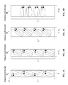
- FIG. 4A through 4D illustrate the changing of the magnetic domains within a ferromagnetic material, from a initial state where there is no applied magnetic field and almost no common orientation in the pattern of the domains, to where an applied magnetic field produces a saturation effect, and most of the magnetic domains have become aligned with the magnetic field direction.
- FIG. 5 shows a microelectronic device and its dimensions in the lengthwise and transverse directions.
- FIG. 6 shows the microelectronic device of FIG. 5 , with the coating of the present invention having been applied to first and second sides of the device.
- FIG. 7 shows the microelectronic device of FIG. 5 , with the coating of the present invention having been applied to two pairs of sides of the device.
- FIG. 8 shows a conventional E-core of a transformer, and the planes of interest that would require coating by the composition of the present invention.
- Ferrite magnetics as well as other ferromagnetic materials, exhibit the property of magnetostriction, which is where the magnetic domains within the material change direction while in the presence of a magnetic field, resulting in small changes in the dimensions of the material.
- Magnetic devices which are constrained by their means of support or which must be encapsulated with a rigid material, exhibit a loss in efficiency due to the constraint of the magnetostrictive properties of the ferromagnetic material. Encapsulation of such electronic components is common in hostile environments (e.g., “down-hole” mining/drilling applications, deep-sea operations, etc.), and for military applications, the requirements for which may be found in MIL-T-27E.
- FIG. 4A through 4D illustrate the changing of the magnetic domains within a ferromagnetic material of a microelectronic device 101 .
- the microelectronic device 101 may be in an initial state where it is not exposed to a magnetic field, there is little common orientation in the pattern of the domains, and the device may have initial dimension of “L O ” and “S.” Any small amount of common orientation therein would be present as a permanent magnetic bias.
- the microelectronic device 101 may be exposed to a small magnetic field of strength H 1 , which may result in minimal of alignment of the magnetic domains in the device with the direction of the magnetic field.
- the dimension of the material in the direction of alignment may increase from the initial state of “S” to “S+ ⁇ S 1 ,” the amount of induced micro-strain for the particular material, for that particular magnetic field strength.
- a further increase in the magnetic field to strength H 2 may result in further alignment of the magnetic domains and a corresponding increase in micro-strain (material dimension of “S+ ⁇ S 2 ”), until the magnetic field strength reaches the saturation value for the particular material, denoted as H 3 , at which most of the magnetic domains in the device have become aligned with the magnetic field direction.
- the problem with microelectronic devices is exacerbated by the high flux densities that are desirable in order to reduce the size and weight of magnetics, which is where the magnetostrictive effect is most pronounced.
- the buffering system of the present invention significantly reduces the compressive and expansive forces upon magnetic cores, thereby reducing losses typically experienced in devices which employ ferromagnetic materials having a high magnetostriction coefficient and which operate at moderate to high flux densities.
- the system of the present invention is a specially devised coating, which may be applied uniformly, or may alternatively be applied in accordance with one of the particular methods disclosed herein.
- composition of the present invention is illustrated in FIG. 3 .
- the composition serves to provide the compressibility of a gas in a solid system to achieve satisfactory mechanical buffering of microelectronic components.
- the composition of the coating material may be primarily an elastomeric polymer binder.
- the binder may form 20 percent of the composition by volume, and may be a low viscosity soft dimethyl silicone plus toluene and/or a very low viscosity silicone diluent, although other binder materials could also be used, such as epoxides, urethanes, vinyls, rubbers (e.g., polyisoprene, polybutadiene, neoprene, etc), perfluoroelastomers, polyethylene, polysulfide, and natural organic adhesives.
- the chosen viscosity of the dimethyl silicone aids in the amount of Expancels that can be incorporated into the composition, while nonetheless maintaining a workable mixture.
- the binder When properly formed, the binder may exhibit a Shore A hardness of less than 25, resulting in a soft buffer material that accommodates three-dimensional movement and alleviates stress concentrations.
- the composition also includes gas-filled polymer shell microspheres carried in the elastomeric polymer binder.
- the microspheres may form 80 percent of the composition by volume.
- the suitable microspheres are preferably 20 microns in diameter or smaller, and may be formed of acrylonitrile or vinylidene Chloride.
- the microspheres may be the dry, expanded, gas filled Expancel® microspheres that are available from AkzoNobel, in Duluth, Ga.
- the gas utilized may be isobutane.
- the microspheres are ideally dispersed uniformly throughout the binder, which is initially achieved by mixing during preparation.
- the microsphere fill is desirable maximized.
- Utilizing microspheres having a diameter of 20 microns or less optimizes the volume of microspheres, but also maintains a sufficiently high mean free path in the binder.
- the use of larger spheres resulted in minimizing the volume of spheres that might be mixed into the adhesive vehicle.
- the use of smaller, random sized spheres—being smaller than 20 microns— is also desirable.
- the binder is preferably a low viscosity dimethyl silicone, which may result in a viscosity ranging between 10,000 and 50,000 cps. Two different viscosity levels are preferably utilized for different applications of the composition, as discussed hereinafter.
- the low viscosity dimethyl silicone is mixed with a solvent, currently toluene, which may alternatively be a reactive diluent.
- a solvent currently toluene, which may alternatively be a reactive diluent.
- the Expancel microspheres are blended into the mixture of solvent and dimethyl silicone, with mechanical stirring.
- composition may be by a brush, a roller, a syringe, or other suitable application means, after which the coating requires a period of time to dry.
- the composition may be mixed at the time of use or it may be mixed and stored in sealed bottles, which require agitation to reduce material separation prior to application.
- a roller and vibrator may be utilized to maintain the dispersion after formation of the composition.
- Microsphere loading of greater than 70% by volume is achieved with the composition as described, as the microspheres may be compressed to several atmospheres of pressure to thereby provide exceptional mechanical buffering for the microelectronic component.
- FIG. 1 illustrates use of the composition on microelectronic components, such as the small ferrite transformers in the “PV” power supply board shown therein, which are operating at a moderately high flux density.
- Test data for the coating applied thereto is shown in FIG. 2 .
- the Series 1 data represents the no-load input current of a transformer encapsulated in an epoxy
- the Series 2 data represents the same transformer buffered in a coating of the composition of the present invention, which is then encapsulated in the same epoxy.
- the coating may reduce losses by greater than 50%.
- the coating may be applied over each of the surfaces of the component (all of the planes of interest), which may be necessary in certain cases, such as for microelectronic components to be utilized in “down-hole” (mining/drilling) applications, deep-sea operations, etc.
- Using a thickness of approximately 15 mils may suffice in most cases (note—a “mil” equals a thousandth of an inch).
- the thickness of the composition to be applied may be determined mathematically to provide a mechanical buffer based on the particular component and its usage, and based on the particular encapsulation material. Specifically, the thickness of the composition applied may be determined based upon the overall expected dimensional changes of the encapsulation material, due to its coefficient of thermal expansion and an expected operating temperature range of the component, plus the expected shrinkage of that encapsulation material during polymerization and the overall mass which shall be exerting a force upon the magnetic core, plus the dimensional changes of the component as a result of the flux density resulting in magnetostriction of the magnetic core. (Note, for a discussion of flux density, see, U.S. Pat. No. 6,084,499 to Faulk for “Planar Magnetics with Segregated Flux Paths,” the disclosures of which are incorporated herein by reference).
- Polymer encapsulation materials for use on microelectronic components typically include epoxides and urethanes, but other materials may also be used, such as the rubbers (Polyisoprene, polybutadiene, neoprene, etc.), polysulfides, and pefloroelastomers.
- the linear coefficient of thermal expansion (TCE) for those families of materials range between 12 ppm/deg C. to greater than 200 ppm/deg C. In most magnetic applications epoxides are the primary choice with typical TCE's being in the range of 40-80 ppm/deg. C.
- the materials of choice for encapsulation of microelectronic components in space limited applications have a TCE ranging between 12 ppm and 20 ppm.
- the encapsulating material may expect to experience a temperature ranges of +130 degrees C. to ⁇ 55 degrees C.
- the thickness of the coating may be tailored—be correlated—to the dimensions of the component (i.e., T S ⁇ T L ), since the resultant total micro-strain experienced is dependent upon the overall dimensions ( ⁇ L/L-units of micro-length per unit length). Therefore, in the “L” direction, which may undergo a greater total micro-strain, the coating thickness T L may be greater than the thickness T S , as the mechanical buffering to be provided in the “S” direction by the coating of thickness T S , generally speaking, need not be nearly as large.
- the inherent shrinkage during polymerization (curing) of the encapsulating material may generally range from 0.1 to slightly greater than 0.4%. (0.4% is on the lower side for most epoxides). Therefore, for a one by one inch rectangle cured at 125 degrees C., the total shrinkage “S” would be 0.004 inches due to the polymerization, and 2.16E-3 inches for the reduction in temperature from the 125 cure temperature to ⁇ 55 degrees C., a total of 6.16E-3 inches.
- a proportionality factor may be used to determine the optimal coating thickness for each of its three pairs of sides.
- Another consideration may further reduce the necessity of utilizing a uniform coating thickness, a practice which would unnecessarily sacrifice space about the microelectronic component—space which may not ideally or practically be available.
- a determination of the magnetic domains in the microelectronic component 101 of FIG. 5 may be made, and may be determined to be the same as those of FIG. 4A .
- the magnetic field direction will constantly be producing positive magnetostriction in the same component directions—for example the “S” direction—the coating need only therefore be applied to those corresponding surfaces at which a support member will restrict dimensional changes of the component. Therefore, as seen in FIG.
- a coating of suitable thickness may be applied to only those two surfaces.
- the coating thickness on each surface may be different (i.e., T S1 ⁇ T S2 ).
- a localized application of coating may be performed only at the mounting location experiencing such minimal contact.
- the composition may be applied using adhesive dispensing equipment, such as by using a brush, or a roller, or other such means.
- composition of the current invention on the ferrite transformers in the “PV” power supply board shown in FIG. 1 , it is advantageous to manufacture two compositions of different viscosities, to be utilized in two separate applications.
- a lower viscosity composition may preferably be applied using a syringe for under-filling the transformer—to fill the area between the core and the printed wiring board (PWB) as well as well as around the legs of the ferrite which are “buried” within the PWB, so a somewhat thinner mixture is necessarily used.
- This composition may have a viscosity of approximately 10,000 cps, and may be formed by adding additional solvent to the mixture, which flashes off.
- a second, higher viscosity composition may be applied to the sides of the transformers for buffering the perimeter, and may be deposited with a larger diameter syringe, or a brush to better control the thickness of the coating.
- This composition may have a viscosity of approximately 50,000 cps.
Landscapes
- Engineering & Computer Science (AREA)
- Power Engineering (AREA)
- Manufacturing & Machinery (AREA)
- Coils Or Transformers For Communication (AREA)
- Paints Or Removers (AREA)
Abstract
Description
Claims (1)
Priority Applications (1)
| Application Number | Priority Date | Filing Date | Title |
|---|---|---|---|
| US13/859,827 US9362039B2 (en) | 2013-04-10 | 2013-04-10 | Composition and method of application to reduce magnetostriction losses in encapsulated microelectronic components |
Applications Claiming Priority (1)
| Application Number | Priority Date | Filing Date | Title |
|---|---|---|---|
| US13/859,827 US9362039B2 (en) | 2013-04-10 | 2013-04-10 | Composition and method of application to reduce magnetostriction losses in encapsulated microelectronic components |
Publications (2)
| Publication Number | Publication Date |
|---|---|
| US20140308438A1 US20140308438A1 (en) | 2014-10-16 |
| US9362039B2 true US9362039B2 (en) | 2016-06-07 |
Family
ID=51686979
Family Applications (1)
| Application Number | Title | Priority Date | Filing Date |
|---|---|---|---|
| US13/859,827 Active 2034-06-01 US9362039B2 (en) | 2013-04-10 | 2013-04-10 | Composition and method of application to reduce magnetostriction losses in encapsulated microelectronic components |
Country Status (1)
| Country | Link |
|---|---|
| US (1) | US9362039B2 (en) |
Citations (1)
| Publication number | Priority date | Publication date | Assignee | Title |
|---|---|---|---|---|
| US4722943A (en) * | 1987-03-19 | 1988-02-02 | Pierce & Stevens Corporation | Composition and process for drying and expanding microspheres |
-
2013
- 2013-04-10 US US13/859,827 patent/US9362039B2/en active Active
Patent Citations (1)
| Publication number | Priority date | Publication date | Assignee | Title |
|---|---|---|---|---|
| US4722943A (en) * | 1987-03-19 | 1988-02-02 | Pierce & Stevens Corporation | Composition and process for drying and expanding microspheres |
Also Published As
| Publication number | Publication date |
|---|---|
| US20140308438A1 (en) | 2014-10-16 |
Similar Documents
| Publication | Publication Date | Title |
|---|---|---|
| Li et al. | A highly adjustable magnetorheological elastomer base isolator for applications of real-time adaptive control | |
| Li et al. | Development and characterization of a magnetorheological elastomer based adaptive seismic isolator | |
| Martin et al. | Magnetostriction of field-structured magnetoelastomers | |
| Ginder et al. | Magnetorheological elastomers in tunable vibration absorbers | |
| Li et al. | A state-of-the-art review on magnetorheological elastomer devices | |
| Aloui et al. | Magneto-rheological response of elastomer composites with hybrid-magnetic fillers | |
| Zhu et al. | Broadband energy harvesting through a piezoelectric beam subjected to dynamic compressive loading | |
| Manoharan et al. | Dynamic characterization of a laminated composite magnetorheological fluid sandwich plate | |
| US10304604B2 (en) | Deformable inductive devices having a magnetic core formed of an elastomer with magnetic particles therein along with a deformable electrode | |
| Wahab et al. | Fabrication and investigation on field-dependent properties of natural rubber based magneto-rheological elastomer isolator | |
| Kim et al. | Stiffness control of magnetorheological gels for adaptive tunable vibration absorber | |
| Yan et al. | The structural, electronic, magnetic and mechanical properties of quaternary Heusler alloys ZrTiCr Z (Z= Al, Ga, In, Si, Ge, Sn): a first-principles study | |
| Kwon et al. | Viscoelastic and mechanical behaviors of magneto-rheological carbonyl iron/natural rubber composites with magnetic iron oxide nanoparticle | |
| Giordano et al. | Thermal effects in magnetoelectric memories with stress-mediated switching | |
| Diguet et al. | From dipolar interactions of a random distribution of ferromagnetic particles to magnetostriction | |
| CN109972667B (en) | A composite structure magnetorheological elastomer negative stiffness isolator | |
| Zayak et al. | Role of shuffles and atomic disorder in Ni–Mn–Ga | |
| La et al. | Muscle-like high-stress dielectric elastomer actuators with oil capsules | |
| Xu et al. | Vibration control of platform structures with magnetorheological elastomer isolators based on an improved SAVS law | |
| Feng et al. | The prestress-dependent mechanical response of magnetorheological elastomers | |
| US9362039B2 (en) | Composition and method of application to reduce magnetostriction losses in encapsulated microelectronic components | |
| Kumar et al. | Active control of cylindrical shell with magnetostrictive layer | |
| Ueno et al. | Magnetic force control with composite of giant magnetostrictive and piezoelectric materials | |
| de Lacheisserie et al. | From bulk to film magnetostrictive actuators | |
| Liu et al. | Control–structure interaction for micro-vibration structural control |
Legal Events
| Date | Code | Title | Description |
|---|---|---|---|
| AS | Assignment |
Owner name: JPMORGAN CHASE BANK, N.A., NEW YORK Free format text: SECURITY AGREEMENT;ASSIGNORS:AEROFLEX INCORPORATED;AEROFLEX PLAINVIEW, INC.;AEROFLEX COLORADO SPRINGS, INC.;REEL/FRAME:030514/0343 Effective date: 20130529 |
|
| AS | Assignment |
Owner name: AEROFLEX PLAINVIEW, INC., NEW YORK Free format text: ASSIGNMENT OF ASSIGNORS INTEREST;ASSIGNOR:WALZ, HERMAN;REEL/FRAME:031325/0429 Effective date: 20130905 |
|
| STCF | Information on status: patent grant |
Free format text: PATENTED CASE |
|
| MAFP | Maintenance fee payment |
Free format text: PAYMENT OF MAINTENANCE FEE, 4TH YEAR, LARGE ENTITY (ORIGINAL EVENT CODE: M1551); ENTITY STATUS OF PATENT OWNER: LARGE ENTITY Year of fee payment: 4 |
|
| AS | Assignment |
Owner name: COBHAM LONG ISLAND INC., NEW YORK Free format text: CHANGE OF NAME;ASSIGNOR:AEROFLEX PLAINVIEW INC.;REEL/FRAME:055550/0842 Effective date: 20190102 |
|
| AS | Assignment |
Owner name: COBHAM LONG ISLAND LLC, VIRGINIA Free format text: ENTITY CONVERSION;ASSIGNOR:COBHAM LONG ISLAND INC.;REEL/FRAME:061299/0518 Effective date: 20211228 Owner name: COBHAM ADVANCED ELECTRONIC SOLUTIONS INC., VIRGINIA Free format text: MERGER;ASSIGNOR:COBHAM LONG ISLAND LLC;REEL/FRAME:060862/0608 Effective date: 20211230 |
|
| AS | Assignment |
Owner name: JPMORGAN CHASE BANK, N.A., AS COLLATERAL AGENT, ILLINOIS Free format text: SECURITY INTEREST;ASSIGNORS:CAES COLORADO SPRINGS LLC;COBHAM ADVANCED ELECTRONIC SOLUTIONS INC.;REEL/FRAME:062337/0939 Effective date: 20230109 |
|
| MAFP | Maintenance fee payment |
Free format text: PAYMENT OF MAINTENANCE FEE, 8TH YEAR, LARGE ENTITY (ORIGINAL EVENT CODE: M1552); ENTITY STATUS OF PATENT OWNER: LARGE ENTITY Year of fee payment: 8 |
|
| AS | Assignment |
Owner name: FRONTGRADE TECHNOLOGIES INC., COLORADO Free format text: CHANGE OF NAME;ASSIGNOR:COBHAM ADVANCED ELECTRONIC SOLUTIONS INC.;REEL/FRAME:068308/0737 Effective date: 20230123 |