US936193A - Fire-escape. - Google Patents
Fire-escape. Download PDFInfo
- Publication number
- US936193A US936193A US45374508A US1908453745A US936193A US 936193 A US936193 A US 936193A US 45374508 A US45374508 A US 45374508A US 1908453745 A US1908453745 A US 1908453745A US 936193 A US936193 A US 936193A
- Authority
- US
- United States
- Prior art keywords
- fire
- building
- shaft
- cables
- latch
- Prior art date
- Legal status (The legal status is an assumption and is not a legal conclusion. Google has not performed a legal analysis and makes no representation as to the accuracy of the status listed.)
- Expired - Lifetime
Links
- 238000004804 winding Methods 0.000 description 3
- 238000010276 construction Methods 0.000 description 2
- 230000001105 regulatory effect Effects 0.000 description 1
- 239000011435 rock Substances 0.000 description 1
- 238000005096 rolling process Methods 0.000 description 1
Images


Classifications
-
- E—FIXED CONSTRUCTIONS
- E06—DOORS, WINDOWS, SHUTTERS, OR ROLLER BLINDS IN GENERAL; LADDERS
- E06C—LADDERS
- E06C7/00—Component parts, supporting parts, or accessories
- E06C7/003—Indicating devices, e.g. user warnings or inclinators
Definitions
- mnxsvk a can! can mommnocmwkzns, WASHZNGYUN. u. c.
- This invention relates to fire escapes, and one. of the principal objects of the same is to provide a simple, reliable and efiicient fire escape which is not accessible to thieves or robbers but which can be instantly made accessible to occupants of the house or buildmg.
- Another object of the invention is to provide a fire escape in which the cables for lowering the occupants are wound upon spools or drums and locked in this position until they are needed for use and which will be instantly unwound upon turning a crank or handle in case of fire.
- Still another object of the invention is to provide a fire escape which is held in position in a casing near the top of a building and which can be instantly rendered accessible by turning a crank or handle and in which the movement of said crank or handle will throw an electric switch to ring a bell or all the bells in the building to alarm the occupants.
- Another object of the invention is to provide an improved gripping device for engaging the cable to permit the occupant to descend with safety to the ground.
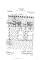
- Figure 1 is a front elevation of a building provided with a fire escape made in accordance with my invention.
- Fig. 2 is a vertical sectional View taken on the line 22 of Fig. 1, and looking in the direction indicated by the arrows.
- Fig. 3 is a similar View taken on the line 33 of Fig. 1, looking in the direction indicated by the arrows.
- Fig. at is a perspective View of the cable grip.
- Fig. 5 is a central longitudinal section through the same.
- Fig. 6 is a horizontal section on the line 66 of Fig. 5, looking in the direction of the arrow.
- the numeral 1, Fig. 1 designates the wall of a building, and located near the roof of a building is a casing 2 which is designed to inclose the operative mechanism of my fire escape.
- Journaled in suitable brackets 3 is the main shaft 1-, said shaft having secured at suitable intervals thereon spools or drums 5. Wound upon these drums are cables 6, said cables each having a weight 7 on the lower end thereof, said cables passing through openings in the bottom of the casing 2.
- a sprocket wheel upon the shaft 4 is provided with a sprocket chain 8 which extends through the wall 1 of the building and upon the inside of the building suitable brackets 9 are secured, and journaled in said brackets is a sprocket wheel 10 around which the chain 8 passes.
- a suitable crank 11 is provided for rotating the sprocket wheel 10 and winding the cables 6 upon the spools.
- a brake comprising a flexible strap 12 secured at one end to a pin 13 and at the other end connected to a yoke 1 said yoke being pivoted at 15 to brackets 3.
- the strap 12 is connected to a pin 16 which extends across the yoke 14.
- a weight 20 is provided with oppositely disposed brackets 21 in which is journaled a pintle 22 carrying a roller 23.
- the pintle 22 extends outward at opposite sides of the brackets 21, and to engage and hold the weight in its upper position to press downward upon the lever 17 a double latch 2 L having hooked ends which engage the pintle 22 straddles the brackets 21 on the weight, said latch be ing pivoted at 25 to lugs on a bracket 26.
- Pivoted at 27 to the latch is a connection 28, the lower end of which is pivotally connected at 29 to a lug 30 formed on a shaft 31 journaled in the brackets 3.
- lugs 32 Formed on the shaft 31 are lugs 32, and connected to these lugs is a wire or cable 33 which extends through a suitable tube or housing 34 to acrank arm 35 secured to a shaft 36 mounted in a bearing extending through the wall 1 of the building and provided upon its inner end with a crank arm 36 inclosed within a cap or housing 37.
- One of the lugs 32 has connected to it a wire or suitable flexible device 38 connected at its lower end to an arm 89 connected to a shaft 40 which may be rotated by means of a crank l1 having a contact 42 upon one end adapted to be swung into contact with the terminals 43 of electric wires a l for ringing bells 1n the building.
- a designates the casing of the grip provided with an extension 6 having a slot 0 through which a strap Z is passed, said strap having a snap hook e and a ring f connected to the ends thereof.
- a rounded openings 9 are formed in the ends of the casing a rounded openings 9 are formed.
- Hinged at h to the casing a is a cover 2', and pivoted between projecting lugs j on the cover is a hand lever 7i ⁇ , said lever having spaced pro jections Z extending through an opening min the cover.
- a stop 9 on the end of the lever Zr serves to limit the outward swing of said lever.
- a sliding latch 1 provided with a slot 3 is connected to the side of the casing by means of a screw 6, said latch be ing provided with an angular arm it having a terminal angular lug c which engages the cover 2' to hold it closed. lVhen it is desired to open the cover 2' to connect the grip with the cable 6 the screw 2 is turned until the latch is permitted to slide and carry the lug 0) beyond the end of the casing.
- I claim 1 In a fire escape, the combination with a main shaft journaled to brackets secured to a building,-of spools on said shaft, cables on said spools, means for winding said cables on said spools, a brake wheel on said shaft, a brake strap applied to said brake wheel, a lever to which said brake strap is connected, a sliding weight for holding said lever in position to apply said brake, a latch for holding said weight in one position, and means connected to said latch extending into position to be operated by occupants of the building.
- a fire escape the combination with a casing, of a shaft journaled to brackets secured to a building within said casing, spools on said shaft, cables on said spools, means for winding said cables on said spools, a brake wheel 011 said shaft, a brake strap for said wheel, a lever to which said brake strap is connected, a weight for holding said lever in position to apply said brake, a pivoted latch for holding said weight in one position, means connected to said latch and extending into position to be operated by occupants of the building, and a cap or housing for covering said means.
Landscapes
- Engineering & Computer Science (AREA)
- Mechanical Engineering (AREA)
- Emergency Lowering Means (AREA)
Description
W. E. TURNER. FIRE ESOAPE. APPLICATION FILED SEPT. 19, 1908.
Patented Oct. 5, 1909.
3 SHEETS-SHEET 1.
mnxsvk a can!" can mommnocmwkzns, WASHZNGYUN. u. c.
W. E. TURNER.
- FIRE ESCAPE.
APP-LIOATION FILED SEPT.19, 1908 v 936,193. Patented 00E.5, 1909. a SHEET8SHEET2 Z/Z ZZiamETzt/me w. E. TURNER.
FIRE ESCAPE. APPLICATION FILED SEPT. 19, 1908. 936,193. Patented 0011.5,1909.
3 SHEETS-SHEET 3.
UNITED STATES PATENT OFFICE WILLIAM E. TURNER, OF ROCHESTER, NEW YORK, ASSIGNOR TO IDEAL FIRE ESCAPE 00., OF ROCHESTER, NEW YORK, A CORPORATION OF NEW YORK.
FIRE-ESCAPE.
Specification of Letters Patent.
Patented Oct. 5, 1969.
Application filed September 19, 1908. Serial No. 453,745.
To all whom it may concern:
Be it known that I, WILLIAM E. TURNER, a citizen of the United States of America, residing at Rochester, in the county of Monroe and State of New York, have invented new and useful Improvements in Fire-Escapes, of which the following is a specification.
This invention relates to fire escapes, and one. of the principal objects of the same is to provide a simple, reliable and efiicient fire escape which is not accessible to thieves or robbers but which can be instantly made accessible to occupants of the house or buildmg.
Another object of the invention is to provide a fire escape in which the cables for lowering the occupants are wound upon spools or drums and locked in this position until they are needed for use and which will be instantly unwound upon turning a crank or handle in case of fire.
Still another object of the invention is to provide a fire escape which is held in position in a casing near the top of a building and which can be instantly rendered accessible by turning a crank or handle and in which the movement of said crank or handle will throw an electric switch to ring a bell or all the bells in the building to alarm the occupants.
Another object of the invention is to provide an improved gripping device for engaging the cable to permit the occupant to descend with safety to the ground.
These and other objects may be attained by means of the construction illustrated in the accompanying drawings, in which,
Figure 1 is a front elevation of a building provided with a fire escape made in accordance with my invention. Fig. 2 is a vertical sectional View taken on the line 22 of Fig. 1, and looking in the direction indicated by the arrows. Fig. 3 is a similar View taken on the line 33 of Fig. 1, looking in the direction indicated by the arrows. Fig. at is a perspective View of the cable grip. Fig. 5 is a central longitudinal section through the same. Fig. 6 is a horizontal section on the line 66 of Fig. 5, looking in the direction of the arrow.
Referring to the drawings, the numeral 1, Fig. 1, designates the wall of a building, and located near the roof of a building is a casing 2 which is designed to inclose the operative mechanism of my fire escape. Journaled in suitable brackets 3 is the main shaft 1-, said shaft having secured at suitable intervals thereon spools or drums 5. Wound upon these drums are cables 6, said cables each having a weight 7 on the lower end thereof, said cables passing through openings in the bottom of the casing 2. To wind the cables 6 upon the spools 5 a sprocket wheel upon the shaft 4: is provided with a sprocket chain 8 which extends through the wall 1 of the building and upon the inside of the building suitable brackets 9 are secured, and journaled in said brackets is a sprocket wheel 10 around which the chain 8 passes. A suitable crank 11 is provided for rotating the sprocket wheel 10 and winding the cables 6 upon the spools.
For locking the shaft 4: against rotation l have provided a brake comprising a flexible strap 12 secured at one end to a pin 13 and at the other end connected to a yoke 1 said yoke being pivoted at 15 to brackets 3. The strap 12 is connected to a pin 16 which extends across the yoke 14.
Formed integral with the yoke 14 is an inclined lever 17 having a curved portion 18. To hold the brake strap 12 firmly against the brake wheel 19 a weight 20 is provided with oppositely disposed brackets 21 in which is journaled a pintle 22 carrying a roller 23. The pintle 22 extends outward at opposite sides of the brackets 21, and to engage and hold the weight in its upper position to press downward upon the lever 17 a double latch 2 L having hooked ends which engage the pintle 22 straddles the brackets 21 on the weight, said latch be ing pivoted at 25 to lugs on a bracket 26. Pivoted at 27 to the latch is a connection 28, the lower end of which is pivotally connected at 29 to a lug 30 formed on a shaft 31 journaled in the brackets 3. Formed on the shaft 31 are lugs 32, and connected to these lugs is a wire or cable 33 which extends through a suitable tube or housing 34 to acrank arm 35 secured to a shaft 36 mounted in a bearing extending through the wall 1 of the building and provided upon its inner end with a crank arm 36 inclosed within a cap or housing 37. One of the lugs 32 has connected to it a wire or suitable flexible device 38 connected at its lower end to an arm 89 connected to a shaft 40 which may be rotated by means of a crank l1 having a contact 42 upon one end adapted to be swung into contact with the terminals 43 of electric wires a l for ringing bells 1n the building.
Referring to Figs. 4-, 5 and 6, in which I illustrate my improved cable grip, the letter a designates the casing of the grip provided with an extension 6 having a slot 0 through which a strap Z is passed, said strap having a snap hook e and a ring f connected to the ends thereof. In the ends of the casing a rounded openings 9 are formed. Hinged at h to the casing a is a cover 2', and pivoted between projecting lugs j on the cover is a hand lever 7i}, said lever having spaced pro jections Z extending through an opening min the cover. The terminal ends of the projections Z are beveled upon their inner edges, as at a, and journaled between the projections Z is a roller 0 having a roughened or corrugated periphery, said roller being journaled upon the pin p. A stop 9 on the end of the lever Zr: serves to limit the outward swing of said lever. To hold the cover Z in closed position a sliding latch 1 provided with a slot 3 is connected to the side of the casing by means of a screw 6, said latch be ing provided with an angular arm it having a terminal angular lug c which engages the cover 2' to hold it closed. lVhen it is desired to open the cover 2' to connect the grip with the cable 6 the screw 2 is turned until the latch is permitted to slide and carry the lug 0) beyond the end of the casing.
The operation of my invention may be briefly described as follows :Vi hen a fire is discovered in the building, any person upon any of the floors can turn the crank 36 which will pull downward upon the wire or cable to rock the shaft 31 and pull downward upon the connection 28 to operate the latch 24, raising the hooked portions of said latch from the pintle 22 of the weight 20, said weight then rolling down to the dotted line position in Fig. 3 to permit the inclined portion 17 of the lever to occupy the position shown in dotted lines and to relieve the brake wheel 19 of the stress applied thereto by the strap 12. The shaft 4: thus being relieved of the brake pressure, the weights 7 will descend and carry with them the cables 6 to the ground, and at the same time the electric bells throughout the building will be started to ring by means of the operation of the switch 42. It is to be noted that the cables 6 extend immediately in front of the windows of the buildingl Occupants may readily connect the grips to the cables 6 and can let themselves gradually to the ground, regulating the speed by means of the hand lever 12.
From the foregoing it will be obvious that my fire escape is comparatively simple in construction, cannot readily get out of or der, is insured against the depredations of thieves or robbers, is entirely inclosed against inclement weather and is instantly rendered operative in case of fire.
I claim 1. In a fire escape, the combination with a main shaft journaled to brackets secured to a building,-of spools on said shaft, cables on said spools, means for winding said cables on said spools, a brake wheel on said shaft, a brake strap applied to said brake wheel, a lever to which said brake strap is connected, a sliding weight for holding said lever in position to apply said brake, a latch for holding said weight in one position, and means connected to said latch extending into position to be operated by occupants of the building.
2. In a fire escape, the combination with a casing, of a shaft journaled to brackets secured to a building within said casing, spools on said shaft, cables on said spools, means for winding said cables on said spools, a brake wheel 011 said shaft, a brake strap for said wheel, a lever to which said brake strap is connected, a weight for holding said lever in position to apply said brake, a pivoted latch for holding said weight in one position, means connected to said latch and extending into position to be operated by occupants of the building, and a cap or housing for covering said means.
In testimony whereof I affix my signature in presence of two witnesses.
VILLIAM E. TURNER. lVitnesses ALFRED W. CURTIS, FRANCIS S. MAooMBnR.
Priority Applications (1)
| Application Number | Priority Date | Filing Date | Title |
|---|---|---|---|
| US45374508A US936193A (en) | 1908-09-19 | 1908-09-19 | Fire-escape. |
Applications Claiming Priority (1)
| Application Number | Priority Date | Filing Date | Title |
|---|---|---|---|
| US45374508A US936193A (en) | 1908-09-19 | 1908-09-19 | Fire-escape. |
Publications (1)
| Publication Number | Publication Date |
|---|---|
| US936193A true US936193A (en) | 1909-10-05 |
Family
ID=3004615
Family Applications (1)
| Application Number | Title | Priority Date | Filing Date |
|---|---|---|---|
| US45374508A Expired - Lifetime US936193A (en) | 1908-09-19 | 1908-09-19 | Fire-escape. |
Country Status (1)
| Country | Link |
|---|---|
| US (1) | US936193A (en) |
Cited By (1)
| Publication number | Priority date | Publication date | Assignee | Title |
|---|---|---|---|---|
| US20050274570A1 (en) * | 2004-06-14 | 2005-12-15 | Lemieux David Lawrence | Method and apparatus for assisting multiple climbers |
-
1908
- 1908-09-19 US US45374508A patent/US936193A/en not_active Expired - Lifetime
Cited By (2)
| Publication number | Priority date | Publication date | Assignee | Title |
|---|---|---|---|---|
| US20050274570A1 (en) * | 2004-06-14 | 2005-12-15 | Lemieux David Lawrence | Method and apparatus for assisting multiple climbers |
| US7198134B2 (en) * | 2004-06-14 | 2007-04-03 | General Electric Company | Method and apparatus for assisting multiple climbers |
Similar Documents
| Publication | Publication Date | Title |
|---|---|---|
| US388491A (en) | Fire escape | |
| US293215A (en) | eobertbaab | |
| US289318A (en) | smith | |
| US285806A (en) | Fire-escape | |
| US493490A (en) | Fiee escape | |
| US326726A (en) | John ditteiok | |
| US797464A (en) | Fire-escape. | |
| US646635A (en) | Fire-escape. | |
| US1369802A (en) | Cabl o | |
| US299850A (en) | Fire-escape | |
| US916825A (en) | Fire-escape. | |
| US300090A (en) | Fire-escape | |
| US1316604A (en) | Fire-escape | |
| US197709A (en) | Improvement in fire-escapes | |
| US398992A (en) | Fire-escape | |
| US570151A (en) | beeez | |
| US201050A (en) | Improvement in fire-escapes | |
| US276736A (en) | Fire-escape | |
| US737106A (en) | Fire-escape. | |
| US538095A (en) | Lamp-hanger | |
| US482654A (en) | Fire-escape | |
| US193489A (en) | Improvement in fire-escapes | |
| US210596A (en) | Improvement in fire-escapes | |
| US513913A (en) | Transom-lifter | |
| US486041A (en) | Fire-escape |